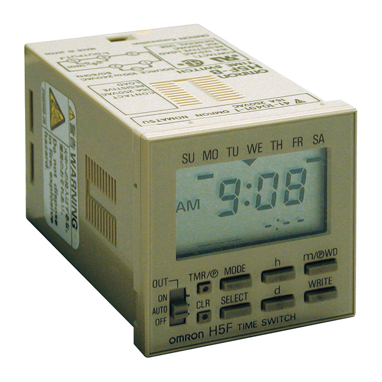
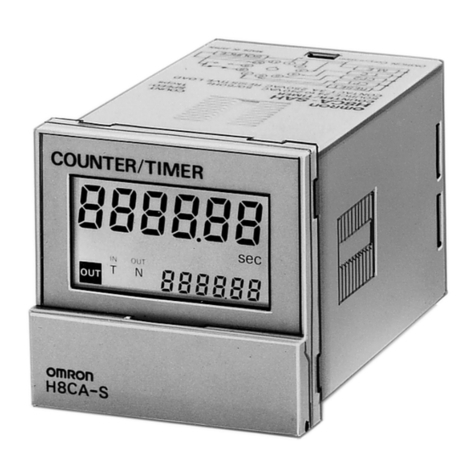
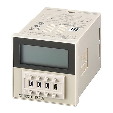
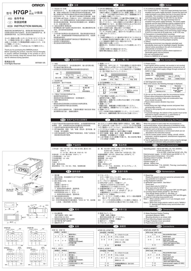
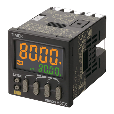
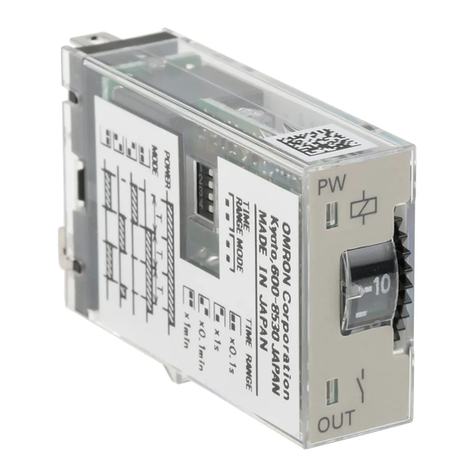
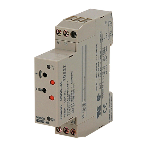
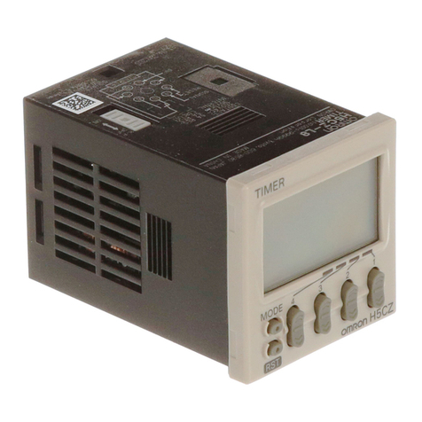
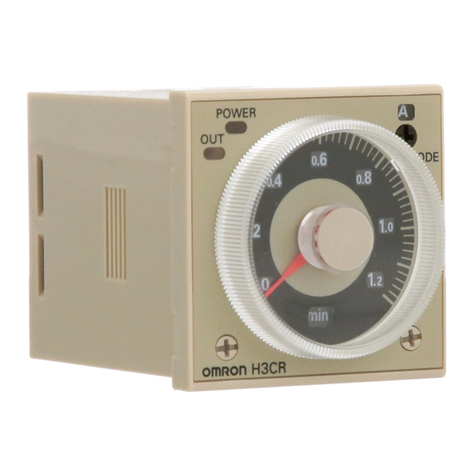
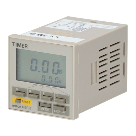
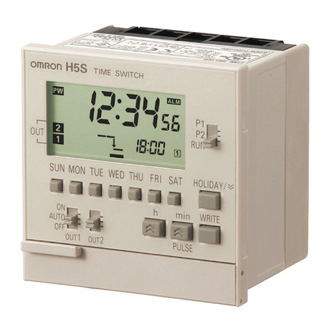
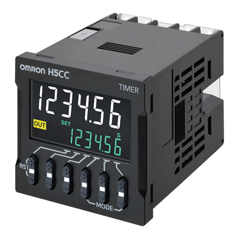
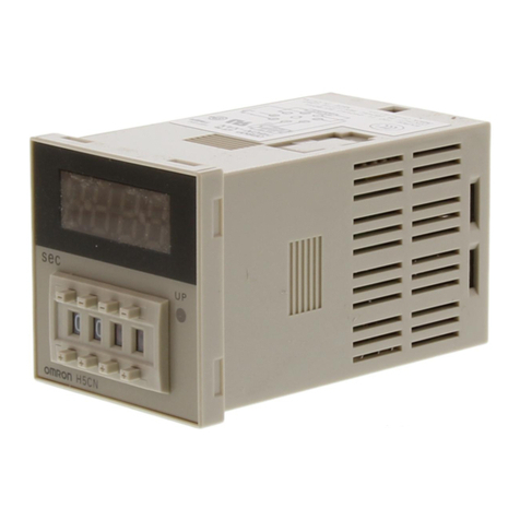
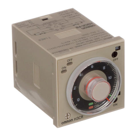
Omron H3CR User manual

1
Solid-state Timer
H3CR
Please read and understand this catalog before purchasing the products. Please consult your OMRON representative if you have any questions
or comments. Refer to Warranty and Application Considerations (page 52), and Safety Precautions (page 22, 44, 51).
DIN 48 ✕ 48-mm Multifunctional Timer Series
• Conforms to EN61812-1 and IEC60664-1 4 kV/2 for Low
Voltage, and EMC Directives.
• Approved by UL and CSA.
• Lloyds/NK approvals.
• Six-language instruction manual provided.
■Broad Line-up of H3CR Series
Note: H3CR-AS, H3CR-A8S: Transistor output models
Contents
Solid-state Timer
H3CR-A .......................................................................................................................................... 2
H3CR-F........................................................................................................................................... 26
H3CR-G.......................................................................................................................................... 34
H3CR-H .......................................................................................................................................... 42
Common to ALL Timers
Operation........................................................................................................................................ 52
Accessories .................................................................................................................................... 54
Safety Precautions.......................................................................................................................... 58
H3CR
Multifunctional Timer Twin Timer Star-delta Timer Power OFF-delay Timer
H3CR-GH3CR-F
11-pin model
8-pin model
11-pin model
8-pin model
8-pin model
8-pin model
11-pin model
H3CR-A
H3CR-A
H3CR-AS
H3CR-AP
H3CR-A8
H3CR-A8S
H3CR-A8E
8-pin with
instantaneous
contact output
model
H3CR-F
H3CR-FN
H3CR-F8
H3CR-F8N
H3CR-G8L
H3CR-G8EL
H3CR-HRL
H3CR-H8L
H3CR-H8RL
H3CR-H

26
Solid-state Twin Timers
H3CR-F
DIN 48 × 48-mm Twin Timers
• Wide power supply ranges of High Voltage 100 to 240 VAC/100
to 125 VDC and Low Voltage 24 to 48 VAC/12 to 48 VDC.
• ON- and OFF-times can be set independently and so
combinations of long ON- or OFF-time and short OFF- or ON-
time settings are possible.
• Twenty-four time ranges from 0.05 s to 300 h depending on the
model to be used.
• Models with a flicker ON start or flicker OFF start are available.
• Easy sequence checks through instantaneous outputs for a
zero set value at any time range.
• Length, when panel-mounted with a Socket, of 80 mm or less.
• 11-pin and 8-pin models are available.
For the most recent information on models that have been
certified for safety standards, refer to your OMRON website.
Model Number Structure
■Model Number Legend
Note: When your order, specify the power supply voltage.
Ordering Information
■List of Models
H3CR - F @ @ - @ @
1 2 3 5 4
1. Classification
F: Twin timers
2. Configuration
3. Twin Timer Mode
4. Time Range
None: 11-pin socket
8: 8-pin socket
None: Flicker OFF start
N: Flicker ON start
5. Supply Voltage
None: 0.05 s to 300 h models
100-240AC/100-125DC: 100 to 240 VAC/100 to 125 VDC
24-48AC/12-48DC: 24 to 48 VAC/12 to 48 VDC
Operating modes Supply voltage 0.05 s to 300 h models
11-pin models 8-pin models
Flicker OFF start 100 to 240 VAC/100 to 125 VDC H3CR-F 100-240AC/100-125DC H3CR-F8 100-240AC/100-125DC
24 to 48 VAC/12 to 48 VDC H3CR-F 24-48AC/12-48DC H3CR-F8 24-48AC/12-48DC
Flicker ON start 100 to 240 VAC/100 to 125 VDC H3CR-FN 100-240AC/100-125DC H3CR-F8N 100-240AC/100-125DC
24 to 48 VAC/12 to 48 VDC H3CR-FN 24-48AC/12-48DC H3CR-F8N 24-48AC/12-48DC
Note: Specify both the model number and supply voltage when ordering.
Example: H3CR-F 100-240AC/100-125DC
Supply voltage

H3CR-F
27
■Accessories (Order Separately)
Adapter, Protective Cover and Hold-down Clip
Note:
*1
*2
Sockets
Note: 1. @@
2.
3.
Terminal Cover
Note:
Name/specifications Models
Flush Mounting Adapter Y92F-30
Y92F-73 *1
Y92F-74 *1
Protective Cover Y92A-48B *2
Hold-down Clip
(Sold in sets of two)
For PF085A Socket Y92H-8
For PL08 or PL11 Sockets Y92H-7
Timer Round Sockets
Pin Connection Terminal Models
P2CF-11
P2CF-11-E
P3GA-11
PL11
PL11-Q
PLE11-0
P2CF-08
P2CF-08-E
PF085A
P3G-08
PL08
PL08-Q
PLE08-0
Application Model Remarks
For back connecting socket Y92A-48G

H3CR-F
28
Specifications
■General
Note: For details, refer to your OMRON website.
*CCC certification requirements
■Time Ranges
Note: The times that can be set are given. When the time setting knob is turned below “0” until the point where the time setting knob stops, the
output will operate instantaneously at all time range settings.
For details, refer to your OMRON website.
■Ratings
Note: 1. A power supply with a ripple of 20% max. (single-phase power supply with full-wave rectification) can be used with each DC Model.
2. Do not use an inverter output as the power supply. Refer to your OMRON website for details.
3. Refer to your OMRON website when using the Timer together with a 2-wire AC proximity sensor.
Item H3CR-F H3CR-F8 H3CR-FN H3CR-F8N
Operating mode Flicker OFF start Flicker ON start
Pin type 11-pin 8-pin 11-pin 8-pin
Operating/Reset method Time-limit operation/Time-limit reset or self-reset
Output type Relay output (DPDT)
Mounting method DIN track mounting, surface mounting, and flush mounting
Approved standards UL508, CSA C22.2 No.14, NK, Lloyds, CCC: GB/T 14048.5 *
Conforms to EN61812-1 and IEC60664-1 (VDE0110) 4kV/2.
Output category according to EN60947-5-1.
Recommended fuse 0216005 (250VAC, 5A), manufactured by Littelfuse
Rated operating voltage Ue
Rated operating current Ie
AC-15: Ue: 250 VAC, Ie: 3 A
AC-13: Ue: 250 VAC, Ie: 5 A
DC-13: Ue: 30 VDC, Ie: 1.5 A
Rated insulation voltage 250 V
Rated impulse withstand
voltage
(altitude: 2,000 m max.)
4 kV (at 240 VAC)
Conditional short-circuit
current
1000 A
Time unit s (sec) ×10 s (10 sec) min (min) ×10 min (10 min) h (hrs) ×10 h (10 hrs)
Fullscale
setting
1.2 0.05 to 1.2 1.2 to 12 0.12 to 1.2 1.2 to 12 0.12 to 1.2 1.2 to 12
30.3 to 3 3 to 30 0.3 to 3 3 to 30 0.3 to 3 3 to 30
12 1.2 to 12 12 to 120 1.2 to 12 12 to 120 1.2 to 12 12 to 120
30 3 to 30 30 to 300 3 to 30 30 to 300 3 to 30 30 to 300
Rated supply voltage (See notes 1, 2, and 3.) • 100 to 240 VAC 50/60 Hz/100 to 125 VDC
• 24 to 48 VAC 50/60 Hz/12 to 48 VDC
Operating voltage range 85% to 110% of rated supply voltage; 90% to 110% with 12-VDC models
Power reset Minimum power-opening time: 0.1 s
Power consumption 100 to 240 VAC: approx. 10 VA (2.1 W) at 240 VAC
24 VAC/VDC: approx. 2 VA (1.7 W) at 24 VAC
approx. 1 W at 24 VDC
Control outputs Contact output: 5 A at 250 VAC/30 VDC, resistive load (cosφ = 1)
The minimum applicable load is 10mA at 5VDC (P reference value).
Contact materials : Ag-alloy

H3CR-F
29
■Characteristics
Note: Refer to the Life-test Curve (Reference).
■Life-test Curve (Reference)
Accuracy of operating
time
±0.2% FS max. (±0.2% FS ±10 ms max. in ranges of 1.2 and 3 s)
Setting error ±5% FS ±50 ms max.
Reset time 0.1 s max.
Reset voltage 10% max. of rated voltage
Influence of voltage ±0.2% FS max. (±0.2% FS ±10 ms max. in ranges of 1.2 and 3 s)
Influence of temperature ±1% FS max. (±1% FS ±10 ms max. in ranges of 1.2 and 3s)
Insulation resistance 100 MΩ min. (at 500 VDC)
Dielectric strength 2,000 VAC, 50/60 Hz for 1 min (between current-carrying metal parts and exposed non-current-carrying metal parts)
2,000 VAC, 50/60 Hz for 1 min (between control output terminals and operating circuit)
2,000 VAC, 50/60 Hz for 1 min (between contacts of different polarities)
1,000 VAC, 50/60 Hz for 1 min (between contacts not located next to each other)
Impulse withstand
voltage
5kV (between power terminals), however, 1kV for 24 to 48VAC, 12 to 48 VDC
5kV (between current-carrying terminal and exposed non-current-carrying metal parts), however 1.5 kV for 24 to 48 VAC,
12 to 48 VDC
Noise immunity ±1.5 kV (between power terminals), square-wave noise by noise simulator (pulse width: 100 ns/1 µs, 1-ns rise)
Static immunity Malfunction: 8 kV
Destruction: 15 kV
Vibration resistance Destruction: 10 to 55 Hz with 0.75-mm single amplitude for 2 hrs each in three directions
Malfunction: 10 to 55 Hz with 0.5-mm single amplitude for 10 min each in three directions
Shock resistance Destruction: 980 m/s
2
three times each in six directions
Malfunction: 98 m/s
2
three times each in six directions
Ambient temperature Operating: −10°C to 55°C (with no icing)
Storage: −25°C to 65°C (with no icing)
Ambient humidity Operating: 35% to 85%
Life expectancy Mechanical: 20 million operations min. (under no load at 1,800 operations/h)
Electrical: 100,000 operations min. (5 A at 250 VAC, resistive load at 1,800 operations/h) (See note)
EMC (EMI) EN61812-1
Emission Enclosure: EN55011 Group 1 class A
Emission AC Mains: EN55011 Group 1 class A
(EMS) EN61812-1
Immunity ESD: IEC61000-4-2
Immunity RF-interference: IEC61000-4-3
Immunity Burst: IEC61000-4-4
Immunity Surge: IEC61000-4-5
Immunity Conducted Disturbance: IEC61000-4-6
Immunity Voltage Dip/Interruption: IEC61000-4-11
Case color Light Gray (Munsell 5Y7/1)
Degree of protection IP40 (panel surface)
Weight Approx. 100 g
10,000
5,000
1,000
500
100
Load current (A)
30 VDC L/R = 7 ms
250 VAC (cosφ = 0.4)
Switching operations (x 10
3
)
250 VAC/30 VDC
(cosφ = 1)
Reference: A maximum current of 0.15 A can be switched at 125 VDC (cosφ = 1) and
a maximum current of 0.1A can be switched at 125V DC and L/R = 7ms.
In both cases, a life of 100,000 operations can be expected.
The minimum applicable load is 10 mA at 5 VDC (failure level: P).
H3CR-F
30
Connections
■Block Diagrams
H3CR-F/-F8/-FN/F8N
■I/O Functions
■Terminal Arrangement
Inputs
Outputs Control output
H3CR-F8/-F8N H3CR-F/-FN
Note:

H3CR-F
31
Operation
■Timing Chart
Note: 1.
2.
Nomenclature
Operating mode Timing chart
Flicker OFF start
Flicker ON start

H3CR-F
32
Dimensions
Note:
Dimensions with Flush Mounting Adapter
H3CR-F
H3CR-FN
H3CR-F8
H3CR-F8N
×
×
Y92F-30 Flush Mounting Adapter (Order Separately)
Note: 1.
2.
Mounting Hole Dimensions
(Conform to DIN 43700.)
Y92F-73 Flush Mounting Adapter (Order Separately)
Note:
*
Note:

H3CR-F
33
■Accessories (Order Separately)
Protective Cover
Y92A-48B
Hold-down Clip
Y92H-8
Hold-down Clip
Y92H-7
Y92F-74 Flush Mounting Adapter (Order Separately)
Note:
Note:
Dimensions with Front Connecting Socket
P2CF-08-@/P2CF-11-@
Dimensions with Back Connecting Socket
P3G-08/P3GA-11
* Note:

52
Operation (Common)
Note:
■Basic Setting
Setting of Selectors
Selection of Operating Mode
• H3CR-A Multifunctional Timer
Selection of Time Unit and Time Range
• H3CR-A Multifunctional Timer
✕✕✕
@
@
• H3CR-F Twin Timers

H3CR
53
• H3CR-G Star-delta Timers
• H3CR-H Power OFF-delay Timers
Setting of Time
■Using the Time Setting Ring for H3CR-A/-G
Locking the Set Time
Limiting the Setting Range

H3CR
54
Accessories (Order Separately) (Common)
Note:
Note:
Flush Mounting Adaptor
−
−
Y92F-30
Panel Cutout
Note1:
Note2:
±
±
±
±
−
−
±
Y92F-70/-73
Y92F-71/-74
Panel Cutout
Note:
Note:
Note:
Note:
*
*
*
*

H3CR
55
Track Mounting/Front Connecting Socket
Y92F-38
P3G
Back Connecting Socket
Unit insertion
direction *
Y92F-30
Flush Mounting Adapter
43.2
96
96
45+0.6
0
45+0.6
0
70±0.4
70±0.4
81 dia.
Four, 5 dia.
*
Insert H3CR timer unit from
front side of adapter.
7.8 3 4.5
35.4
4
40±0.2
40±0.2
7.8
4
35.4
20.3
19
3
1.3
5 4.5
70 max.
50 max.
20.3 max.
P2CF-08-E (Finger Safe Terminal Type)
Conforming to VDE0106/P100
Surface Mounting Holes
Two, 4.5 dia. or two, M4
50 max.
70 max.
21.5 max.
P2CF-08
Eight,
M3.5 × 7.5 sems
Two, 4.5 dia.
holes
Terminal Arrangement/
Internal Connections
(Top View)
Two, 4.5 dia.
holes
Eight,
M3.5 × 7.5 sems
40±0.2
7.8
3 4.5
35.4
4
7.8
4
40±0.2
35.4
30
5 4.5
3
1.2
Surface Mounting Holes
Two, 4.5 dia. or two, M4
70 max.
50 max.
31.2 max.
P2CF-11-E (Finger Safe Terminal Type)
Conforming to VDE0106/P100
70 max.
50 max.
31.2 max.
P2CF-11
Eleven,
M3.5 × 7.5 sems
Terminal Arrangement/
Internal Connections
(Top View)
Two, 4.5 dia.
holes
Eleven,
M3.5 × 7.5 sems

H3CR
56
Back Connecting Socket
Mounting Track
×
×
P3GA-11
Fin
ger Safe Terminal Cover
Conformin
g to VDE0106/P100
Y92A-4
8G
P3G-0
8
Terminal Arrangement/
Internal Connections
(Bottom View)
Terminal Arrangement/
Internal Connections
(Bottom View)
(Attachment for P3G-0
8/P3GA-11
Socket)
±
± ±
±
PFP-100N2
PFP-100N, PFP-50N
Note:
End Plate
PFP-M
Spacer
PFP-S

H3CR
57
Time Setting Ring/Panel Cover for H3CR-A/-G
Using the Time Setting Ring for H3CR-A/-G
Note:
Locking the Set
Time
Limiting the setting
range
Y92S-27
Time Setting A
Y92S-28
Time Setting B
Y92S-28
Time Setting C
Y92P-48GL
Light Gray
Y92P-48GB
Black

H3CR
58
Safety Precautions for All H3CR Models
Note: The undermentioned is common for all H3CR models.
Warning Indications
Meaning of Product Safety Symbols
Risk of fire and explosion due to arcing and relay heat
generation that accompanies switching. Do not use in an
environment where flammable or explosive gas is present.
The H3CR series uses a transformer-less power
supply. Exercise full caution as there is a risk of
electrical shock if input terminal is touched when
power voltage is applied.
The service life of the output relay varies widely
depending on switching capacity and switching
conditions. Use only within the rated load and
electrical life count, based on actual conditions of use.
Risk of contact sticking and burning if used past the
service life. Always use a load current that does not
exceed the rating, and if a heater is used, use a thermal switch in the
load circuit.
Do not remove the outer casing.
In rare circumstances there is a risk of slight electrical
shock, fire, or device damage. Do not disassemble,
modify, repair, or otherwise touch the inside.
In rare circumstances there is a risk of fire if the
screws become loose. Tighten the terminal screws to
the specified torque (1.08N
·
m).
1. Do not use the Timer in the following locations.

•Locations with radical temperature changes.
•Locations with high humidity that may result in condensation.
•Locations with excessive vibration or shock.
•Locations with corrosive gas or dust.
•Locations where the Timer is exposed to sprayed water, oil, or
chemicals.
2. Pay the utmost attention not to make mistakes in polarity when
wiring the Timer.
3. Do not connect anything to terminals that are not used.
4. Risk of internal element damage if a voltage that exceeds the
rating is applied.
5. Using a surge absorber is recommended if surge voltages occur.
6. Verify that the power and output LEDs (LCD) are operating
normally. In some usage environments, the LEDs/LCD/ resin
components may deteriorate faster than normal, resulting in
display failure. Inspect and replace regularly.
7. When disposing of this product, follow the procedures for disposal
of industrial waste that apply in your region.
8. Verify that the product is the desired product before use.
9. Exercise caution as the outer casing of the timer may be
immersed in organic solvents (thinner, benzene, etc.), strong
alkali, or strong acids.
Changing the Setting
Do not change the time unit, time range, or operation mode while the
Timer is in operation, otherwise the Timer may malfunction.
The time unit and time range can be set with the respective selectors
turned clockwise or counterclockwise.
The selectors are of notched so that they will snap when they are
properly set. Do not set the selectors midway between notches,
otherwise the Timer may break or malfunction.
Do not use H3CR-A models (except for H3CR-A@S) in flicker mode
at the lowest selector setting, or H3CR-F models at the lowest
selector setting. Doing so may result in damage to contacts.
CAUTION
Indicates a potentially hazardous situation
which, if not avoided, may result in minor
or moderate injury or in property damage.
Precautions for
Safe Use
Supplementary comments on what to do
or avoid doing, to use the product safely.
Precautions for
Correct Use
Supplementary comments on what to do
or avoid doing, to prevent failure to
operate, malfunction or undesirable effect
on product performance.
Used to warn of the risk of electric shock under
specific conditions.
Used for general prohibitions for which there is no
specific symbol.
Use to indicate prohibitions when there is a risk of
minor injury from electrical shock or other source if
the product is disassembled.
Used for general mandatory action precautions for
which there is no specified symbol.
CAUTION
Precautions for Safe Use
Precautions for Correct Use

H3CR
59
Power Supplies
A DC power supply can be connected if its ripple factor is 20% or
less and the mean voltage is within the rated operating voltage range
of the Timer.
An AC power supply can be connected to the power input terminals
without regard to polarity. A DC power supply must be connected to
the power input terminals as designated according to the polarity of
the terminals.
Make sure that the voltage is applied within the specified range,
otherwise the internal elements of the Timer may be damaged.
Connect the power supply voltage through a relay or switch in such a
way that the voltage reaches a fixed value at once, otherwise the
Timer may not be reset or a timer error may result.
Be aware that the operating voltage will rise by 5% if the rated
voltage is applied to the Timer continuously while the ambient
temperature is close to the maximum permissible ambient
temperature.
The power supply circuit of any H3CR-A model (except for H3CR-
A@S), H3CR-F 100-to-240-VAC model, and H3CR-G model is a
switching circuit. If the power line connected to the power supply
circuit has a transformer with high inductance, a counter-
electromotive voltage will be induced by the inductance. To suppress
the voltage, apply a CR filter to the power supply line.
Apply the power voltage at once through the switch and relay
contacts. If not applied at once, power reset may not take place or
time-up may occur.
When the power is turned on, a rush current (refer to your OMRON
website) may flow briefly and the timer may not start if there is
insufficient power capacity. Use a power supply with sufficient
capacity.
Mounting Direction
There are no restrictions to the mounting direction.
Precautions for EN61812-1
Conformance
The H3CR Series as a built-in timer conforms to EN61812-1
provided that the following conditions are satisfied.
Make sure that no voltage is applied to any terminals before
dismounting the Timer from the Socket.
The output section of the H3CR is provided only with basic isolation.
The H3CR itself is designed under the following conditions:
•Overvoltage category III
•Pollution degree 2
•Isolation
Operation parts: Reinforced isolation
−With clearance of 5.5 mm and creepage distance of 5.5 mm at
230 VAC
Output: Basic isolation (See note)
−With clearance of 3 mm and creepage distance of 3 mm at
230 VAC
Note: The 11-pin model ensures basic isolation by itself and also
ensures basic isolation with the 11-pin model mounted to the
OMRON P2CF-11-@ or P3GA-11 Socket.
Connect the two output contacts different in polarity to the loads so
that they will be the same in potential.
Others
If the Timer is mounted to a control board, dismount the Timer from
the control board or short-circuit the control board circuitry before
carrying out a voltage withstand test between the electric circuitry
and non-charged metal part of the Timer. This protects the internal
circuitry of the Timer from damage.
If the timer is left for an extended time at high temperature in the
time-up state (internal relay ON), the internal components
(electrolytic capacitors, etc.) may deteriorate faster than normal. For
this reason, use in combination with a relay, and avoid leaving in the
time-up state for an extended time (for example, one month or
longer). (Excluding H3CR-H)
Reference example
Use as shown below.
Cleaning
Do not use solvents such as thinner. Use commercially available
alcohol.
X
X
1
T X
2
X
2
/b T/a X
1
/a X
1
/a
: Auxiliary relay,
MY relay, etc.
In the interest of product improvement, specifications are subject to change without notice.
ALL DIMENSIONS SHOWN ARE IN MILLIMETERS.
To convert millimeters into inches, multiply by 0.03937. To convert grams into ounces, multiply by 0.03527.

Terms and Conditions Agreement
Read and understand this catalog.
Warranties.
Limitation on Liability; Etc.
Suitability of Use.
Programmable Products.
Performance Data.
Change in Specifications.
Errors and Omissions.

Authorized Distributor:
In the interest of product improvement,
specifications are subject to change without notice.
Cat. No. L084-E1-09 0520 (0696)
© OMRON Corporation 1996-2020 All Rights Reserved.
OMRON Corporation
Industrial Automation Company
OMRON ELECTRONICS LLC
2895 Greenspoint Parkway, Suite 200
Hoffman Estates, IL 60169 U.S.A.
Tel: (1) 847-843-7900/Fax: (1) 847-843-7787
Regional Headquarters
OMRON EUROPE B.V.
Wegalaan 67-69, 2132 JD Hoofddorp
The Netherlands
Tel: (31)2356-81-300/Fax: (31)2356-81-388
Contact: www.ia.omron.com
Kyoto, JAPAN
OMRON ASIA PACIFIC PTE. LTD.
No. 438A Alexandra Road # 05-05/08 (Lobby 2),
Alexandra Technopark,
Singapore 119967
Tel: (65) 6835-3011/Fax: (65) 6835-2711
OMRON (CHINA) CO., LTD.
Room 2211, Bank of China Tower,
200 Yin Cheng Zhong Road,
PuDong New Area, Shanghai, 200120, China
Tel: (86) 21-5037-2222/Fax: (86) 21-5037-2200
CSM_2_10
Other manuals for H3CR
3
This manual suits for next models
17
Table of contents
Other Omron Timer manuals