manuals.online logo
Brands
  1. Home
  2. •
  3. Brands
  4. •
  5. Ono Sokki
  6. •
  7. Measuring Instrument
  8. •
  9. Ono Sokki DS-2000 Series User manual

Ono Sokki DS-2000 Series User manual

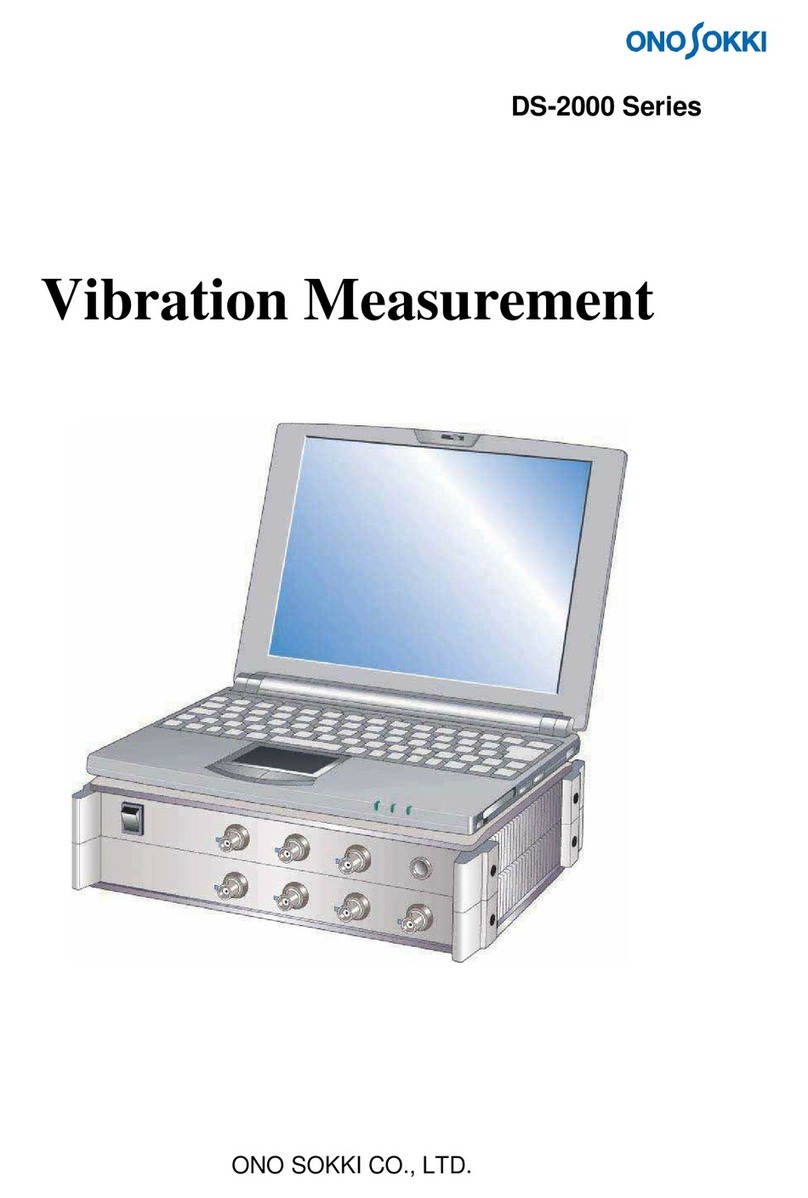
ONO SOKKI CO., LTD.
DS-2000 Series
Measurement of Frequency
Response Function
1
Contents
1. Flow Chart to Measurement
2. Device Connections
3. DS-2000 Setup
4. Measurement
1.
Flow Chart to Measurement
The following explains procedures for measuring the frequency response function using an
impulse hammer.
Connect accelerometer and
impulse hammer.
• Set an input source.
• Set a sensor sensitivity.
• Set unit name.
• Adjust voltage range (Y-axis).
• Adjust frequency range (X-axis).
• Set trigger.
• Process data.
• Save data.
Connect an
accelerometer and an
impulse hammer to the
DS-2000.
Set the type of the
connected sensor and the
data described in the data
sheet of the connected
sensor to the DS-2000.
Perform trial measurement
and adjust data to make it
legible.
Save and load data.
2
2.
Device Connections
Connect an "accelerometer" and an "impulse hammer" to the DS-2000. Although the
acceleration sensor comes in two types, built-in amplifier type and charge output type, the
use of the built-in amplifier type is assumed here. Connect each sensor with the DS-2000
series as shown below.
The following shows an example of direct connection of an impulse hammer without using
an amplifier. However, when output magnification is to be performed by the amplifier, input
the output from the amplifier of the impulse hammer to the DS-2000.
Excitation response
Waveform signal
DS-2000
3
3.
DS-2000 Setup
3-1 Preparing for Setup
To correctly operate the connected impulse hammer and accelerometer and display data,
set operating conditions and sensitivity of the sensor to an FFT analyzer. Sensitivity and
operating condition settings are described in the "Calibration Chart" supplied with the
accelerometer to be used.
Calibration Chart Supplied with "NP-3130" Acceleration Sensor with Built-in Amplifier
Voltage sensitivity (at 160Hz)
Charge sensitivity (at 160Hz)
Capacitance*
Drive current (constant current drive type)
Remarks
Inspected
*The cable capacitance is excluded. However, the cable capacitance is included with the directly connected type.
Set data items of ①and ②on the calibration chart to the FFT.
①Voltage sensitivity indicates a voltage to be output by the sensor with an acceleration
of 1m/s2. Here, a voltage of 9.75mV is output.
4
付いている。
②Drive current indicates that a current of 2.4mA is sent to the sensor.
In the documents supplied with the "GK-3100" impulse hammer, necessary data are
described as follows:
The hammer is provided with an
extender (weight for weight
adjustment).
Plastic and vinyl
tips are used.
Presence or absence of an extender attached to the rear end of the
impulse hammer, with different voltage outputs per 1N (newton).
To make the vibration force constant, it is necessary to hammer an object under
measurement using the weight of the hammer itself instead of the force of arm or hand.
Therefore, it is recommended to attach an extender at the rear end of the hammer.
Here, make sure that the voltage output per 1N (newton) is 2.38mV/N.
About tip at the end of hammer
The frequency of the excitation force by the impulse hammer can be roughly adjusted
by changing the material of the tip at the end of the hammer.
□
HARD TIP (metal)
Enables steep impulse rise and vibration up to high frequencies. However, there is a risk
of double-hammering (hammering twice), and the power spectral density is low.
□
SOFT TIP (vinyl)
The power spectral density is high, and the vibration energy is concentrated in low regions.
However, vibration with several Hertz or less is difficult.
□
MEDIUM TIP (plastic)
Provides intermediate characteristics between a metal tip and a vinyl tip.
5
3-2 Input Source Setup
Set sensitivity, operating conditions, etc. of the sensor connected to the DS-2000. Here,
procedures will be explained on the premise that CH1 is used for impulse hammer and
CH2 for accelerometer.
Click the Input menu and then select Voltage Range.
(1) For both channels, uncheck the [AUTO] check box.
(2) For [Coupling], select AC (AC coupling) for both channels.
(3) Open the [Source] dialog.
CH1: When inputting a signal from the impulse hammer power supply, select [BNC]
(when directly inputting a signal from the impulse hammer, select SENSOR(2mA)).
CH2: Since the drive current in the Calibration Chart is "2.4mV," select
[SENSOR(2.0mA)].
(4) Click [OK] to confirm the settings.
Select AC for both channels.
Uncheck AUTO. Select a drive
current of the
accelerometer.
Click OK to confirm
the settings.
6
3-3 Unit Conversion
It is inconvenient that the vibration waveform is still displayed as a voltage. Use the unit
calibration function to allow direct read from voltage to acceleration. Click the Input menu
and then select Unit / Calibration to open the dialog.
Input hammer vibration force unit N (newton).
Input acceleration unit m/s2. Set a voltage value (sensor
sensitivity) per unit.
Click OK to confirm
the settings.
Thereby, the unit of CH1 (impulse hammer side) is converted to N (newton) for excitation
force, and CH2 (accelerometer side) to m/s2 for acceleration, enabling direct reading with
each unit.
7
3-4 Display Selection
Setup in screen
At the time of data measurement, specify the top for time waveform display of CH1 and
the bottom for time waveform of CH2.
Screen setup
Select a channel and a function to be displayed from the setup drop-down lists.
Select channel. Select display function.
To change the screen, click the Data Type label at the top left of the data screen to
activate it and then make the above settings.
Display time waveforms of CH1 and CH2.
8
3-5 Adjusting Voltage Range
Set a voltage range and a frequency range to a value suitable for measurement.
While hammering the object under measurement (with a constant force) as if it drops by its
weight, select a range for displaying a signal waveform as large as possible so that the
LED of the LEVEL indicator for each channel does not light up.
LEVEL indicator lights in red at level over.
Set an input range.
Select a range so that level over does
not occur while hammering.
9
3-6 Applying
Trigger
Stop a waveform at a desired position in the screen using the trigger function to make it
easier to observe the waveform. Click the Input menu to open the Trigger Set.
Apply trigger to the waveform of CH1 (impulse hammer) while hammering the object under
measurement.
Set a trigger position as leftward as possible in the screen so that the waveform can be
observed without problem.
Select repeat trigger to apply
trigger repeatedly. Select internal trigger to apply trigger with a
hammer input signal.
Numerical input is
also possible.
Click on a point in the screen to the level and
position to apply the trigger. Set a position as
leftward as possible in the screen.
Click OK to confirm
the settings.
Do not change the Y-axis scale from default.
If the scale is changed, scale and level (%)
axes are unable to match.
10
Press the TRIG button in the screen to set to the trigger-ready state.
Waveform of impulse hammer
Waveform of accelerometer
When you hammer the object under measurement and then the waveform stops at a
specified position, trigger is OK.
11
3-7 Window Setup
Since the signal of the impulse hammer is a single-shot impact signal, select the
rectangular window without compensation. Click the Input menu and then select Time
Window. Then, make setting for each channel.
Select [Rect] to every
channels.
12
3-8 Determining Frequency Range
Determine a frequency range based on the following:
Select it within the analysis frequency range of the sensor (accelerometer)
Select it from the frequency resolution to be focused (The lower the frequency range,
the higher the frequency resolution becomes.)
Select it from the maximum number of resonance frequencies to be observed (The
higher the frequency range, the more numbers of observable modes becomes.)
Select a frequency with
the mouse.
13
3-9 AD Over Cancel Setup
This function eliminates data if voltage of an input signal exceeds a limit because of
excessive hammering. Click the Input menu and then select Sampling condition.
Check A/D OverCancel.
*Please check whether the trigger is applied
before turning on the A/D over cancel.
14
3-10 Average
Setup
To minimize a measurement error, data is averaged. In this case, summation averaging of
spectrum is used. (This setting is selected as initial setup. If changed, setup is required.)
The standard number of averaging is 4 or 8. Click the Input menu and then select Average.
Select Power Sum
(Spectrum Summation).
Input 8 or around.
15
4 Measurement
4-1 PerformingAveraging and Starting measurement
Perform averaging and start measurement.
Press AVG. * Make sure that TRIG is ON.
When you press the switch and a signal is input, averaging starts automatically. Start
hammering. When the signal (hammering) is input for the specified number of averaging,
averaging stops automatically. Perform measurement while monitoring two time-waveform
screens, impulse hammer and acceleration detector, to check whether double-
hammering (hammering twice) occurs.
Trigger lamp Number of averaging
16
4-2 Checking FrequencyResponse Function Data under
Observation
Here, check data by displaying the frequency response function at the top and the
coherence function at the bottom.
* The coherence function represents the correlation between input and output signals.
Coherence becomes worse if noise is mixed between input and output or if rattling or
other nonlinear factor is present.
The higher the coherence, the higher becomes the reliability of the frequency response
function. The coherence is displayed as a level between 0 and 1 in the Y-axis range.
(The coherence function cannot be calculated without averaging.)
Frequency response function
Coherence function
CAUTION:
1. The copyright of this procedure manual is reserved by Ono Sokki Co., Ltd.
2. Duplication without prior permission is prohibited.
3. This procedure manual explains general measurement procedures. Ono Sokki assumes no
responsibility for data obtained through a specific operation performed by the customer.

Other manuals for DS-2000 Series

3

Other Ono Sokki Measuring Instrument manuals
Ono Sokki CF-7200 Reference guide

Ono Sokki

Ono Sokki CF-7200 Reference guide

Ono Sokki HT-5200 User manual

Ono Sokki

Ono Sokki HT-5200 User manual

Ono Sokki DS-2000 Series User manual

Ono Sokki

Ono Sokki DS-2000 Series User manual

Ono Sokki SE-1520 User manual

Ono Sokki

Ono Sokki SE-1520 User manual

Ono Sokki HT-6200 User manual

Ono Sokki

Ono Sokki HT-6200 User manual

Ono Sokki FT-2500 User manual

Ono Sokki

Ono Sokki FT-2500 User manual

Ono Sokki LV-1800 User manual

Ono Sokki

Ono Sokki LV-1800 User manual

Ono Sokki HT-3200 User manual

Ono Sokki

Ono Sokki HT-3200 User manual

Ono Sokki HR-6800 User manual

Ono Sokki

Ono Sokki HR-6800 User manual

Ono Sokki SE-1200 User manual

Ono Sokki

Ono Sokki SE-1200 User manual

Ono Sokki GE-1400 User manual

Ono Sokki

Ono Sokki GE-1400 User manual

Ono Sokki FT-7100 User manual

Ono Sokki

Ono Sokki FT-7100 User manual

Ono Sokki DS-2000 Series User manual

Ono Sokki

Ono Sokki DS-2000 Series User manual

Ono Sokki TS-3200A User manual

Ono Sokki

Ono Sokki TS-3200A User manual

Ono Sokki SE-2400 User manual

Ono Sokki

Ono Sokki SE-2400 User manual

Ono Sokki FT-7200 User manual

Ono Sokki

Ono Sokki FT-7200 User manual

Ono Sokki DS 0297 User manual

Ono Sokki

Ono Sokki DS 0297 User manual

Ono Sokki CF-4700 User manual

Ono Sokki

Ono Sokki CF-4700 User manual

Ono Sokki HT-6200 User manual

Ono Sokki

Ono Sokki HT-6200 User manual

Ono Sokki DS-2000 Series User manual

Ono Sokki

Ono Sokki DS-2000 Series User manual

Ono Sokki HT-5500 User manual

Ono Sokki

Ono Sokki HT-5500 User manual

Popular Measuring Instrument manuals by other brands

Hanna Instruments HI 96706C instruction manual

Hanna Instruments

Hanna Instruments HI 96706C instruction manual

Leader LV 7770 instruction manual

Leader

Leader LV 7770 instruction manual

MOULDPRO SZxxx0 Series operating instructions

MOULDPRO

MOULDPRO SZxxx0 Series operating instructions

McCrometer FPI Mag 394E Installation, operation and maintenance manual

McCrometer

McCrometer FPI Mag 394E Installation, operation and maintenance manual

Diamond Engineering Officejet 6000 User manual & setup guide

Diamond Engineering

Diamond Engineering Officejet 6000 User manual & setup guide

Gemini iKEY manual

Gemini

Gemini iKEY manual

Evoqua WALLACE & TIERNAN P7 ADVANCED instruction manual

Evoqua

Evoqua WALLACE & TIERNAN P7 ADVANCED instruction manual

Xylem sensus DomoJet user guide

Xylem

Xylem sensus DomoJet user guide

Scientific SM6015A user manual

Scientific

Scientific SM6015A user manual

PKP DR15 operating instructions

PKP

PKP DR15 operating instructions

Endress+Hauser Levelflex FMP50 Safety instructions

Endress+Hauser

Endress+Hauser Levelflex FMP50 Safety instructions

Austro Engine AE300-Wizard user guide

Austro Engine

Austro Engine AE300-Wizard user guide

UEi C165+ quick start guide

UEi

UEi C165+ quick start guide

Funk Amateur FA-VA5 Assembly and operating manual

Funk Amateur

Funk Amateur FA-VA5 Assembly and operating manual

Boxboro RibEye Hardware user manual

Boxboro

Boxboro RibEye Hardware user manual

GE Druck DPI 705 user manual

GE

GE Druck DPI 705 user manual

GE Ultrasonic USM Go Operator's manual

GE

GE Ultrasonic USM Go Operator's manual

Flex ADM 60-T operating instructions

Flex

Flex ADM 60-T operating instructions

manuals.online logo
manuals.online logoBrands
  • About & Mission
  • Contact us
  • Privacy Policy
  • Terms and Conditions

Copyright 2025 Manuals.Online. All Rights Reserved.