Selectable contents vary depending on the rotational condition. There are 5 kinds of measurement algorithms.
MODE Measurement algorithm
A Steady rotation Maximum power spectrum peak detection method
B measurement mode Peak-interval mode method
C Acceleration/deceleration Multi-order peak followup method
D rotation measurement Maximum power spectrum peak followup method
Emode Specific power spectrum peak followup method
Rotational speed candidate selection function
Calculation is performed using the
frequency of the power spectrum's
maximum peak. Measurement is
usually performed in this mode.
The frequency intervals of the each order component in the
rotation are sought sequentially. The most often appeared
frequency interval is judged to be the first-order component of the
rotational speed in order to fix the rotational speed. This is an
effective method when the first-order peak is unstable.
Peak-interval mode method
1st order signal
component
2nd order signal
component
3rd order signal
component
Frequency interval = rotational basic order
Noise component
Frequency (Hz)
Power (dB)
Frequency (Hz)
Maximum power spectrum peak
detection method
Power (dB)
• In C,D, and E mode, the FT-2500 follows up the acceleration/deceleration condition owing to the
internal high speed processing function.
• In C mode, the FT-2500 predicts the peak value which it should be and calculates the rotational
speed even if the maximum peak has been lost.
• In E mode of rotational speed candidate selection, suitable rotational speed can be selected
from maximum of 8 frequency peaks.
Algorithm
Algorithm
2
Advanced Tachometer FT-2500
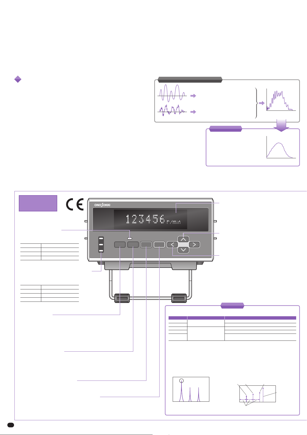
UPPER LEVEL
LOWER
ROTATION
COMP SENS MENU SET
NEXT
KEY PROTECT SAMPLE RECALL
t
t
When the amplitude of rotational signal
is not stable and some of the pulse
signals cannot be detected, the
rotational speed is calculated lower than
it should be.
When the electrical noise is contained in
the rotational signal, the rotational
speed is calculated higher than it should
be owing to the malfunction by noise.
r/min
t
Analog output waveform
Fluctuated display values
Previous or conventional model
Previous or conventional model
r/min
t
Analog output waveform
Stable display values
Measurement using FFT
technology is not affected by
noise and irregular signal
amplitude.
Model FT-2500
Model FT-2500
LED colors Signal level
Green Appropriate signal level
Red Signal level is too high.
Unlit Signal level is too low.
LED colors Comparator status
Green Comparator OFF
Red Comparator ON
Unlit Comparator disabled
Front
No rotational pulse signal is required for a measurement. The rotational speed is
calculated from the frequency signal of light, magnetism, vibration, and sound.
The FT-2500 is an advanced tachometer which measures the rotational speed by the Fast Fourier Transform (FFT)
calculation. Moreover, the FT-2500 can measure the rotational speed from frequency signal of sound, vibration or the
like even though the rotating shaft is not accessible. The FT-2500 allows versatile rotational speed measurements such
as the steady rotation of motor and acceleration/deceleration rotational speed of engine.
• The reflective marks or special machining is not needed to
attach the sensor.
• Because the rotational speed measurement can be
performed easily from the frequency signal of sound or
vibration, no special machining to rotating shaft is
required.
• The measurement under the condition of the change or
acceleration/deceleration in the rotational speed is
available. (When the acceleration/deceleration rotation
measurement mode is selected.)
• Provides rotating direction determination function. (When
the FT-0501 DC Motor Rotation Detector is used.)
• Easy to read fluorescent display.
• Provides both the analog and pulse outputs.
• Ethernet communication function can be added as an
option.
Comparator status display LEDs
LEDs for displaying comparator operation
status of UPPER, LOWER or ROTATION.
< COMP > key
Key for starting/stopping the comparator function. When
comparator function of automatic ON is set at ‘Normal’ , the
comparator function will be OFF at the time of restarting the
main unit. If comparator function of automatic ON is set at
‘Auto’ , the comparator function will be held its state at the
time of restarting of main unit.
< SENS > key
Key for fine adjustment of the sensor sensitivity. Pressing
this key displays the sensitivity level. Press [
] or [
] key
to make fine adjustment of the sensitivity.
< MENU > key
Key to select measurement mode or setup mode.
< SET/NEXT > key
In setup mode, you can go to the next setup item by pressing
this key. Pressing and holding (for approximately 2 seconds)
this key make the key protection function start or stop.
Level monitor LED
This LED is used to monitor the
sensor’s input signal level.
Displaying section
It displays the measurement value.
Displaying item can be selected from
rotational speed (r/min) or frequency
(Hz) in setup mode.
<
> key
In setup mode, use this key to change
the setup value or selected item.
<
/SAMPLE> key
In setup mode, the position of the digit
for inputting the condition can be
moved by pressing this key.
In acceleration/deceleration rotation
measurement mode, it is used for
measurement start or selection of
rotational peak.
Features


