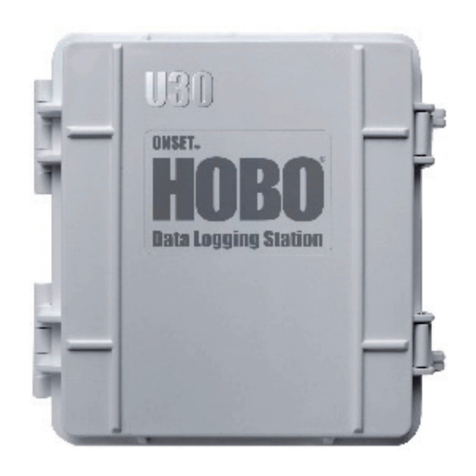
Onset HOBO U30 GSM User manual

Part #: MAN-U30-GSM
Doc #: 11343-D
H
HO
OB
BO
O®
®
U
U3
30
0
G
GS
SM
M
R
Re
em
mo
ot
te
e
M
Mo
on
ni
it
to
or
ri
in
ng
g
S
Sy
ys
st
te
em
m
User’sGuide
onset®
ii HOBO U30 Remote Monitoring System User’s Guide
DANGER! HIGH VOLTAGE HAZARD!
This logger can be used with sensors that may be installed in an energized
electrical enclosure or on an energized conductor. Installation of sensors in an
energized electrical enclosure or on an energized conductor can result in severe
injury or death. These sensors are for installation by qualified personnel only.
To avoid electrical shock, do not install or service these sensors unless you are
qualified to do so. Disconnect and lock out all power sources during installation
and servicing. Please read the user’s manual for instructions and use.
WARNING
This device contains a radio and is not approved for use on airplanes.
Disconnect the batteries before flight.

HOBO U30 Remote Monitoring System User’s Guide iii
Contact Information
For support, please contact the company that you bought the products from: Onset
Computer Corporation or an Onset Authorized Dealer.
Onset Computer Corporation
470 MacArthur Blvd.
Bourne, MA 02532
Mailing Address:
P.O. Box 3450
Pocasset, MA 02559-3450
Phone: 1-800-LOGGERS (1-800-564-4377) or 508-759-9500
Fax: 508-759-9100
Hours of Operation: 8 AM to 5 PM ET, Monday through Friday
E-mail: [email protected]
Main Onset Web site: www.onsetcomp.com
If you purchased the products through an Onset Authorized Dealer, you can also refer
to www.hobohelp.com for support information.
Part #: MAN-U30-GSM
Doc #: 11343-D
©2007–2008 Onset Computer Corporation. All rights reserved. Onset, HOBO,
HOBOware, and HOBOlink are trademarks or registered trademarks of Onset
Computer Corporation for its data logger products and configuration/interface
software. All other trademarks are the property of their respective companies.
Patented Technology (U.S. Patent #s 6,675,098 and 6,343,255)
iv HOBO U30 Remote Monitoring System User’s Guide

HOBO U30 Remote Monitoring System User’s Guide v
Contents
Chapter 1: Introduction........................................................1
Overview .......................................................................... 1
Key features ..................................................................... 2
HOBO U30 Station components ...................................... 3
Chapter 2: Setting up the system .......................................6
Before you begin.............................................................. 6
Communicating with HOBOlink.com................................ 6
Assembling the system .................................................. 11
Chapter 3: Using the HOBO U30 Station..........................25
Working with HOBOlink.com.......................................... 25
Working with HOBOware Pro ........................................ 30
Working with sensors..................................................... 37
Time accuracy................................................................ 39
Memory .......................................................................... 40
Power ............................................................................. 41
Chapter 4: Maintenance.....................................................45
General maintenance..................................................... 45
Inspecting the HOBO U30 Station ................................. 45
Verifying sensor accuracy.............................................. 46
Cleaning the HOBO U30 Station ................................... 46
Maintaining the battery................................................... 46
Chapter 5: Diagnostics and troubleshooting ..................49
Indicator LED behavior .................................................. 49
Problems and solutions.................................................. 52
vi HOBO U30 Remote Monitoring System User’s Guide
Chapter 6: Reference .........................................................57
Detailed specifications ................................................... 57
Supported Smart Sensors and Accessories .................. 60
U30 Accessories ............................................................ 62
Warranty..............................................................................63
Returns........................................................................... 64
Repair Policy .................................................................. 65
Contacting Technical Support........................................ 65
Index ....................................................................................67

Chapter 1: Introduction
HOBO U30 Remote Monitoring System User’s Guide 1
Chapter 1:
Introduction
This chapter discusses the following topics:
•Overview
•Key features
•HOBO U30 Station components
Overview
The HOBO U30 Remote Monitoring System is a data logging system that
can be easily reconfigured and adapted to a wide variety of applications. Up
to 15 channels of data can be recorded and monitored remotely via
HOBOlink™. Or, use HOBOware®Pro software to set up analog data
channels, communicate with the logger locally, and further plot and export
data files downloaded from HOBOlink.com for analysis. In addition, you
can set alarms to trip for specific sensor readings that you select or for
overall system conditions, such as when the memory or battery is running
low.
The HOBO U30 Remote Monitoring System package includes:
•HOBO U30 Station with integrated GSM radio and antenna
•Mounting Kit
•Grounding Wire
•Cable Entry and Sealing Kit
•Optional Analog Sensor Port, if ordered
•Optional Sensor Expander Board, if ordered
Chapter 1: Introduction
2 HOBO U30 Remote Monitoring System User’s Guide
Key features
GSM radio - The HOBO U30 Station contains a Global System for Mobile
(GSM) communications radio module that uses the mobile phone network to
establish an internet connection with HOBOlink.com. By using a web
browser, you can configure and view data from the HOBO U30 Station
anywhere in the world.
Automatic detection of Smart Sensors – The HOBO U30 Station
automatically recognizes Smart Sensors; simply plug them in before logging
begins. No programming, wiring or calibration is required to set them up.
The connections between the Smart Sensors and the logger are digital,
ensuring accurate, reliable data collection and storage. See page 60 for a list
of supported Smart Sensors.
Alarm notification – The HOBO U30 Station supports alarm notification.
When an alarm is detected, the system can trigger the relay contact closure
and send you a notification to your email/mobile phone. Alarms can be set
for individual sensors and for overall system conditions.
Rechargeable battery – The HOBO U30 Station uses a sealed lead-acid
battery that can be recharged via a solar panel or AC adapter. This provides
continuous power to keep the HOBO U30 Station recording and transmitting
data for years.
Optional Analog Sensor Port – The HOBO U30 Station can be optionally
configured with an Analog Sensor Port, which includes two user-
configurable inputs that can accept and provide excitation power to a wide
range of Onset and third-party sensors with 0-20 V or 0-20 mA output. The
Analog Sensor Port is factory-installed.

Chapter 1: Introduction
HOBO U30 Remote Monitoring System User’s Guide 3
HOBO U30 Station components
2. Indicator
LEDs 4. SMA antenna
connector
5. Antenna
12. Battery
connector
14.
External
power
supply
13. Ground
connector
6. Expansion
connecto
r
7. USB port
8. Relay
contacts
11. Smart
Sensor ports
9. Vent
15. Battery
(behind internal
enclosure)
3. Connection LEDs (on board
in internal enclosure)
10. Cable access openings
1. Internal
enclosure
Chapter 1: Introduction
4 HOBO U30 Remote Monitoring System User’s Guide
No. Name Description
1. Internal
enclosure
This provides a second weatherproof housing
for the electronics in the HOBO U30 Station.
There is no need to ever open this, and opening
it will void the warranty.
2. Indicator LEDs There are three Light Emitting Diode (LED)
status indicators.
Logging indicates whether the system is
currently logging.
Alarm indicates if an alarm has been
tripped.
Sensor active indicates that Smart Sensor
network communications are occurring.
For more information on LEDs, refer to
Diagnostics and troubleshooting on page 49.
3. Connection
LEDs
There are two LEDS on the board in the internal
enclosure (to the right of the indicator LEDs)
that blink when the HOBO U30 Station is
contacting a cellular tower and when it is
connected to the HOBOlink.com server. For
more details, see Diagnostics and
troubleshooting on page 49.
4. SMA antenna
connector
This is the connection point for the quad-band
GSM antenna.
5. Antenna This is the quad-band GSM antenna.
6. Expansion
connector
This connector is where the optional Analog
Sensor Port is factory-installed.
7. USB port Plug in a USB cable here to connect directly to
a computer.
8. Relay contacts The Relay can be configured with software for
normally open, normally closed, or pulsed output
upon an alarm condition (max 30 V, 1 Amp).

Chapter 1: Introduction
HOBO U30 Remote Monitoring System User’s Guide 5
9. Vent This vent allows pressure to equalize inside the
enclosure, but does not allow liquid to pass
through.
Note: The pressure inside the case does not
match the outside air pressure exactly so a
barometric pressure sensor deployed within this
case cannot measure the true atmospheric
pressure unless it has its own unrestricted vent
to the outside.
10. Cable access
openings
All cables and wires are routed through a
protective rubber cable channel placed in this
opening. If you are using the optional expander
board for additional Smart Sensors, you will
need to use both cable access openings. See
Steps for assembly on page 12 for details.
11. Smart Sensor
ports
Connect up to five Smart Sensors in these RJ-
12 jacks. Use one port to connect the optional
expander board for additional Smart Sensors.
12. Battery
connector
Plug in the 4-volt sealed lead-acid battery here.
13. Ground
connector
Plug in grounding wire here to ground the
system. Systems that are installed on roofs or
other exposed locations should be grounded.
14. External power
supply
Plug in the compatible solar panel or AC
adapter here.
Important: Always connect or disconnect
external power before the battery. Damage may
occur if the battery is unplugged before the
external power is disconnected.
15. Battery A 4-volt sealed lead-acid (SLA) battery is
located behind the internal enclosure.
Chapter 2: Setting up the System
6 HOBO U30 Remote Monitoring System User’s Guide
Chapter 2:
Setting up the system
This chapter discusses the following topics:
•Before you begin
•Communicating with HOBOlink.com
•Assembling the system
Before you begin
The HOBO U30 Station is designed primarily for use with HOBOlink.com,
which allows for continuous logging and transmission of data using mobile
network technology. There are, however, certain circumstances under which
you might also need to use HOBOware Pro software on a computer
connected to the HOBO U30 Station. Before you set up your system, it is
important to understand when to use HOBOlink.com and HOBOware Pro.
When to use HOBOlink.com When to use HOBOware Pro
Launching
Setting up readout schedules
(connection intervals)
Configuring alarms
Checking data and status
Configuring the Analog Sensor
Port if installed
Changing the default system-
wide relay operation (which is
normally open)
Checking cellular signal strength
Testing individual Smart
Sensors
Additional plotting and analysis
of data files
Communicating with HOBOlink.com
When the HOBO U30 Remote Monitoring System is set up in its permanent
location, it will be transmitting data regularly via cellular communication on
a schedule that you select. Before you set that up, however, you need to
configure the HOBO U30 Station to communicate with HOBOlink.com.
This will involve a test launch.
Step 1: Create a HOBOlink.com account. Go to HOBOlink.com and
follow the instructions to create a user account if you have not already done
so.

Chapter 2: Setting up the System
HOBO U30 Remote Monitoring System User’s Guide 7
Step 2: Register the HOBO U30 Station. Each individual HOBO U30
Station must be registered with HOBOlink.com before you can launch or
configure it further. To register the HOBO U30 Station:
1. Go to HOBOlink.com and log in to your account.
2. Click the Register a Device link and follow the instructions on the
screen. You will need to give the device a nickname. If you will be
setting up more than one device, it is helpful to select a meaningful
name so that you can easily identify it from the list of other devices
in HOBOlink.com. You will also need to enter both the serial
number (SN) and Device Key as part of this process. You can find
both numbers on the label inside the door of the HOBO U30
Station.
Step 3: Configure the device. The device name should be added to the list
on the Devices tab. Click the device you just registered, which will take you
to the Data Files tab. Click the Device Configuration icon at the bottom of
the tab. Change the time zone if necessary.
Step 4: Set up a test launch. Click Launch Configuration in
HOBOlink.com. Enter a launch description (which will also be used as the
filename for the data readouts) and select a logging interval. It is
recommended that you choose a fast logging interval (for example, 1 minute)
so that enough data is recorded for your test. You can change this interval
once the test is complete. For more details on launching, see page 26.
Step 5: Set up the readout schedule. Click Readout Configuration and
enter a connection interval, which is how frequently you want the HOBO
U30 Station to send data to HOBOlink.com. For more details on reading out,
see page 27.
Chapter 2: Setting up the System
8 HOBO U30 Remote Monitoring System User’s Guide
Important: The connection interval that you select is not only the schedule
upon which newly recorded data will be transmitted back to
HOBOlink.com, it is also the amount of time you will have to
wait before any changes you make to launching or reading out
take effect. Select a fast connection interval for this test, such as
10 minutes or you may have to wait a long time for the next
readout. For example, if you type in a connection interval of 10
minutes, you will have to wait 10 minutes for the next
connection. If, however, you set up the connection interval for 1
hour, then you will have to wait an hour until the next
connection before any changes you make take effect. It is better
to set up a fast interval while you make sure everything is
working and then go back and set the connection interval that
you would like to use in your deployment.
Step 6: Plug in one or more Smart Sensors. You may choose any number
of Smart Sensors to test the communication with HOBOlink.com.
Insert the Smart Sensor cables through the cable access opening in bottom of
HOBO U30 Station and plug them into the Smart Sensor port.
Figure 1: One Smart Sensor plugged into a Smart Sensor port
Plug in Smart
Sensors here

Chapter 2: Setting up the System
HOBO U30 Remote Monitoring System User’s Guide 9
If you will be using the optional Smart Sensor expander board (S-ADAPT-
X5-10), you may install it at this time if necessary and plug in additional
Smart Sensors as described in the next section, or wait until you assemble
the system.
If you are using the optional Analog Sensor Port, you will need to configure
that first using HOBOware Pro. See page 32 for details.
Step 7: Plug in the battery. Connect the built-in battery cable to the battery
(you do not need the solar panel or AC adapter for this test launch).
Figure 2: Battery cable plugged in
Step 8: Wait for the first connection and check the data. After the battery
is plugged in, the HOBO U30 Station will automatically connect to the
cellular network and communicate with HOBOlink.com. This process may
take a few minutes. After the HOBO U30 Station completes its first
connection to HOBOlink.com, make sure the data for the Smart Sensors is
there in HOBOlink under Latest Conditions as expected. Let the HOBO U30
Station connect a couple of times checking the data after each connection.
Plug in the battery here
Do not plug in the
battery here (this is
for solar panel or
AC adapter)
Chapter 2: Setting up the System
10 HOBO U30 Remote Monitoring System User’s Guide
Important: Once you are satisfied everything is working properly, you may
want to change the logging interval in the Launch Configuration
and the connection interval in the Readout Configuration to a
slower schedule to preserve battery power (see Maximizing battey
life on page 41). If you are not deploying the system immediately,
you should also disconnect the battery to save battery power and
reduce cellular transmission costs. You can disconnect the
sensors if desired for transporting the system to the field.

Chapter 2: Setting up the System
HOBO U30 Remote Monitoring System User’s Guide 11
Assembling the system
This section explains how to set up your system for deployment. The
instructions assume that you have already communicated with
HOBOlink.com as described in the previous section. If you have not, it is
recommended that you complete those steps on page 6 before assembling the
system.
Required items for assembly
•HOBO U30 Station and Smart Sensors
•Solar panel or AC power adapter
•Optional Smart Sensor expander and expander cable, and bladed
screwdriver or chisel and a file
•Rubber cable channel(s)
•Cable channel retaining bars
•Silicone grease
•Plugs for unused cable channel holes
•Grounding wire
•Sensors attached to optional Analog Sensor Port, 4.0 mm (0.157 in.)
diameter (see steps for more detail)
•Optional relay output wire (user-supplied), 4.0 mm (0.157 in.)
diameter (see steps for more detail)
•Small flat-head screw driver for relay or Analog Sensor Port screw
terminals if using those
•Phillips-head screw driver
•Wrench or socket driver
•Mounting kit and U-bolts
Note: The photos and illustrations in this section focus on one component
per step for clarity. Therefore, not everything that should be installed
is shown in each illustration. Your HOBO U30 Station will likely
look different than the illustrations because you will have more cables
plugged in than shown.
Chapter 2: Setting up the System
12 HOBO U30 Remote Monitoring System User’s Guide
Steps for assembly
Step 1: Install the mounting plates. Screw the mounting plates onto the
back of the HOBO U30 Station case using a Phillips-head screwdriver. Be
careful to orient the plates as shown below so that the screw heads are sunk
into the screw holes.
Figure 3: Installing the mounting plates

Chapter 2: Setting up the System
HOBO U30 Remote Monitoring System User’s Guide 13
Step 2: Mount the HOBO U30 Station to a pole or wall. Mount the
HOBO U30 Station vertically to a mast or pole using the U-bolts and a
wrench or socket driver, or mount it vertically to a wall or board using
screws. Make sure the HOBO U30 Station remains in a vertical position
once it is placed in its deployment location. If it is mounted horizontally,
the antenna will not have optimal range and the battery could be
damaged over time as it is charged. If you are using U-bolts for mounting,
make sure the mounting plates are mounted against the flat part of the U-bolt
saddle clamps.
Figure 4: Mounting to a pole
Step 3: Install and mount all sensors on a tripod and/or in their desired
measurement locations. Follow the instructions in the sensor manuals for
installation and mounting.
Important: All sensors should be mounted at least one foot from the HOBO
U30 Station case because the built-in GSM radio module and
antenna can cause interference with the measurements made by
the sensors. Any excess sensor cables should not be coiled up
and stored inside or within one foot outside the case. The Leaf
Wetness Smart Sensor (S-LWA) is especially sensitive and
should be mounted at least two feet away from the case.
Mount the flat
part of the
clamp to the
mounting plate
Chapter 2: Setting up the System
14 HOBO U30 Remote Monitoring System User’s Guide
Step 4: Knock out secondary access opening and install the optional
Smart Sensor Expander board. If you are using the optional Smart Sensor
expander board, you will need to knock out the piece covering the second
opening, install the board if not is not already factory-installed, and then
connect the two boards with the expander cable.
Knock out the secondary cable access opening:
1. Make sure the HOBO U30 Station is turned off and all cables are
disconnected.
2. Use a hammer and a bladed tool (e.g., screwdriver, chisel) to punch
through at the four corners and at the ends of the secondary cable
access opening knockout.
Figure 5: Knocking out secondary
cable access openings
primary and secondary
cable access openings

Chapter 2: Setting up the System
HOBO U30 Remote Monitoring System User’s Guide 15
3. Punch through along the bottom of the knockout and then tap
sharply in the middle to break into the opening. Remove the
hanging ‘flap’ of material.
Figure 6: Punching through
secondary cable access opening
4. Peel away any residual material.
Figure 7: Removing residual material
Chapter 2: Setting up the System
16 HOBO U30 Remote Monitoring System User’s Guide
5. File any rough edges. For best results, the surfaces in the cable
access opening should be smooth so that the rubber cable channel
gasket will seal.
Figure 8: Filing rough edges
Install the Smart Sensor Expander:
6. Insert one of the two supplied self-tapping screws into each end of
the expander, lower onto the two standoffs near the bottom of the
case, and screw into place. Note: The contacts of the expander jacks
should be nearest to the bottom of case as shown. Be careful not to
trap the battery cable behind the expander.
Figure 9: Installing Smart Sensor expander
DO NOT trap battery
cable behind expander
screws
contacts

Chapter 2: Setting up the System
HOBO U30 Remote Monitoring System User’s Guide 17
Alternate method: Place expander (without the screws) onto the
standoffs. Apply a small amount of clear grease (the grease supplied
with this kit can be used) at the end of the screwdriver to hold
screws while lowering them into place.
Figure 10: Alternate method for
installing Smart Sensor expander
Install Expander Cable:
7. Plug one end of the supplied expander cable into the rightmost jack
of the expander board and the other end into the rightmost jack of
the built-in board as shown.
Figure 11: Installing expander cable
Chapter 2: Setting up the System
18 HOBO U30 Remote Monitoring System User’s Guide
Step 5: Plug in all Smart Sensors into the HOBO U30 Station (if not
already plugged in) making sure all cables are routed through the cable
access opening(s). Keep in mind that any Smart Sensors plugged in after
logging has already begun will be ignored.
Figure 12: Smart Sensor cables pulled through
cable access openings

Chapter 2: Setting up the System
HOBO U30 Remote Monitoring System User’s Guide 19
Step 6: Install sensors to the optional Analog Sensor Port. Make sure all
wires attached to the Analog Sensor Port are routed through the cable access
opening. For details on configuring the Analog Sensor Port with HOBOware
Pro, see page 32.
Figure 13: Analog Sensor Port wires connected
Tip: Because these cables will need to fit into the holes in the rubber cable
channel, the ideal cable diameter is 0.157 in (4.0 mm). If the cable is
too small, build up the diameter using heat shrink. If it is too big and
you are using the secondary cable access opening, then place the cable
through the leftmost hole in the rubber cable channel where the
diameter can be up to 0.25 in (6.4 mm). If you are not using the
secondary opening or the cable is still too big, then splice on another
cable with a smaller diameter to fit through the hole. See the steps later
in this section for working with the rubber cable channel.
Connect sensors to
Analog Sensor Port
Chapter 2: Setting up the System
20 HOBO U30 Remote Monitoring System User’s Guide
Step 7: Install the optional relay output wire. Make sure any wire you use
is routed through the cable access opening (see the tip in the previous step
about recommended cable diameter). For details on configuring alarms to
activate the relay, see page 28.
Figure 14: Relay output wire connected
Connect the relay
output wires here

Chapter 2: Setting up the System
HOBO U30 Remote Monitoring System User’s Guide 21
Step 8: Install grounding wire if applicable. Insert the grounding wire
through the opening and plug it into the ground connector. The grounding
wire is recommended if you are using the Wind Speed and Direction Smart
Sensor (S-WCA-MXXX) or if you are installing the HOBO U30 Station on a
roof or in a location with exposure to lightning. The grounding wire may
also be helpful in reducing sensor errors when installing the HOBO U30
Station near other radio or electrical equipment or antennas.
Figure 15: Grounding wire connected
Step 9: Route the cable for the solar panel or AC adapter through the
opening, but do not connect it yet. Later in this section you will connect
the battery and then plug in the solar panel or AC adapter. You need to route
the solar panel or AC adapter cable through the opening at this point,
however, so that you can properly install the rubber cable channel.
Step 10: Install the rubber cable channel(s). All cables and wires should
be routed through the cable access opening at this point. If you are using the
Smart Sensor expander board, make sure those cables are routed through the
secondary cable access opening.
Connect the
grounding
wire here
Chapter 2: Setting up the System
22 HOBO U30 Remote Monitoring System User’s Guide
1. Apply a small amount of silicone grease (about the size of a pea)
onto your fingertip and then work a light coating into the top,
bottom, and two ends (the sides with no holes) of the rubber cable
channel. Also put a light coating on the inside of the two halves of
the cable channel.
Figure 16: Greasing the cable channel
2. Hold the channel just below the HOBO U30 Station case (with the
channel’s hinged side on the left and the taper facing in). Open the
channel and lay the cables and wires into the grooves. Note: The
solar panel or AC adapter cable must be in the leftmost (larger
diameter) groove. Use the small rubber plugs to fill any unused
grooves. Center the thick part of the plugs in the groove. Plug ‘tails’
can face in or out.
Figure 17: Cables in grooves
Plug ‘tails’ can face
in or out
Taper faces in

Chapter 2: Setting up the System
HOBO U30 Remote Monitoring System User’s Guide 23
3. Close the channel, making sure the cables, wires, and any plugs
remain in their grooves. Press the channel into the opening. To
reduce the amount of excess cable in the case (especially when
several Smart Sensors are connected), gently pull the cables toward
you as you press the channel into place. Press the channel in until it
is flush with the outside of the case. (When fully seated, the channel
will project slightly into the inside of the case.)
Figure 18: Channel pressed into case
4. If you are using the Smart Sensor expander board, then repeat these
steps with the second cable channel. Use the larger plug for the
leftmost hole if necessary.
5. Screw the retaining bars on to the case to secure the channel(s). The
bars should be flat against the case. Finger-tighten only! Do not use
a screwdriver to tighten the thumb screws. (You may need a
screwdriver to loosen them after time in the field.)
Figure 19: Retaining bars installed
Chapter 2: Setting up the System
24 HOBO U30 Remote Monitoring System User’s Guide
Step 11: Plug in the battery first and then the solar panel or AC
adapter, and then verify that the HOBO U30 Station powers up
properly.
Important: If you need to turn off the power, be sure to unplug the solar
panel or AC adapter first and then unplug the battery. Damage
may occur to the HOBO U30 Station if the battery is unplugged
before disconnecting the solar panel or AC adapter.
Figure 20: Solar panel or AC adapter cable plugged in
The HOBO U30 Station should power up and connect to HOBOlink.com. If
you wish to start a new launch after the assembly is complete, use
HOBOlink to relaunch the station. Under Launch Configuration in
HOBOlink.com, select Force Relaunch on Next Connection.
Also be sure to close the door and snap the hinges shut on the HOBO U30
Station case when you are finished. Consider using padlocks to secure the
case.
If you are deploying the HOBO U30 Remote Monitoring System in a
location where rodents are present, it is recommended that you protect all
exposed cables and wires with conduit to prevent rodents from chewing the
cables.
Plug this solar
panel or AC
adapter cable in
second
Plug the
battery in first

Chapter 3: Using the HOBO U30 Station
HOBO U30 Remote Monitoring System User’s Guide 25
Chapter 3:
Using the HOBO U30 Station
This chapter discusses the following topics:
•Working with HOBOlink.com, including setting up launches,
readouts and alarms, and checking status
•Working with HOBOware Pro, including configuring the Analog
Sensor Port, configuring the relay, checking signal strength, and
viewing data files
•Working with sensors
•Time accuracy
•Memory
•Power, including maximizing battery life, battery voltage, and
estimating battery life without external power
Working with HOBOlink.com
This section describes how to use the HOBO U30 Station with
HOBOlink.com, including:
•Launching
•Setting up the readout configuration
•Configuring alarms
•Checking status and data
If you have not used HOBOlink.com to register and configure the HOBO
U30 Station, go to Communicating with HOBOlink.com on page 6. Note:
This manual only covers the basic functions of HOBOlink. For more
information on using HOBOlink, refer to the online help on HOBOlink.com
(under the Support tab).
Chapter 3: Using the HOBO U30 Station
26 HOBO U30 Remote Monitoring System User’s Guide
Launching
Because this system is designed to allow continuous logging and
transmission of data, once you launch the HOBO U30 station it will always
use the schedule you have selected in HOBOlink.com for logging and
reading out. Any changes you make to the Launch Configuration will take
effect the next time the HOBO U30 Station connects to HOBOlink.com.
Important: Although the HOBO U30 Remote Monitoring System can be
used with HOBOware Pro, it is strongly recommended that
launching be done exclusively through HOBOlink.com. Any
launch that you have set up with HOBOlink.com will override
the launch parameters set with HOBOware Pro.
The following table explains the features available in the Launch
Configuration.
Launch Configuration
Feature Description
Logging Interval This is how frequently the HOBO U30 Station
records data measurements.
Sampling Interval This is how frequently the HOBO U30 Station
makes measurements for a Smart Sensor that
supports measurement averaging. The average
over the logging interval will be logged. Enable this
feature only if you are using one or more of the
following Smart Sensors that support measurement
averaging:
12-bit Temperature S-TMB-M0XX
12-bit 4-20 mA Input Adapter S-CIA-CM14
12-bit Voltage Input Adapter S-VIA-CM14
Photosynthetically Active Radiation (PAR)
S-LIA-M003
Silicon Pyranometer (Solar Radiation)
S-LIB-M003
Barometric S-BPB-CM50
Wrap Around When
Full
By default, the HOBO U30 Station is set to Wrap
Around When Full. This means logging will
continue once the 512K memory is full, with the
newest measurements overwriting the oldest
measurements, and new data will continue to be
uploaded to HOBOlink. If you wish to stop logging
once the memory is full, and then disable Wrap
Around When Full.

Chapter 3: Using the HOBO U30 Station
HOBO U30 Remote Monitoring System User’s Guide 27
Launch Configuration
Feature Description
Note: The HOBO U30 Station will continue to
contact HOBOlink once the memory is full and
logging has stopped, but there will not be any new
data uploaded and current readings will no longer
be updated.
Force Relaunch on
Next Connection
Select this option when you want to start a
completely new launch the next time the HOBO
U30 Station connects to HOBOlink.com. You must
select this option when new sensors are
installed, otherwise the new sensors will not be
recognized.
Full Readout Upon
Power Reset
Select this option if you want an immediate
complete readout of the HOBO U30 Station after
unplugging the battery or other power interruption.
This feature may be useful if you have a system
failure and you are unable to bring a computer into
the field to perform a direct USB download. This
option is very data intensive and may not be
available with all levels of service. Check the
details of your service plan.
Setting up the Readout configuration
The HOBO U30 Station connects to HOBOlink.com at a regular interval that
you select (for example, every 2 hours) and reads out all the data since the
last time the data was read out. The data is saved in a file and displayed as
graphs in HOBOlink.com. You can also download data files and view them
in HOBOware Pro for further data plotting and analysis. Click Readout
Configuration in HOBOlink.com to change the connection interval.
To preserve battery power and/or minimize connection charges, enable the
Night Mode feature. This allows you to set up two readout schedules with
more frequent connections during the day and less frequent connections
during the night. (Or, you could set the faster rate to be during the night for
applications such as frost monitoring.) From Readout Configuration in
HOBOlink.com, select Night Mode and enter the starting and ending time
when you want the system to use a different schedule, and the connection
rate for this time period.
Chapter 3: Using the HOBO U30 Station
28 HOBO U30 Remote Monitoring System User’s Guide
Configuring alarms
You can set two types of alarms for the HOBO U30 Station: system alarms
and sensor alarms. Click Go To Alarms in HOBOlink.com to access these
features.
System alarms Sensor alarms
HOBOlink.com can send you an
email or text message when:
There is a sensor failure
The memory is running low
The battery is low (4.05 volts,
which is approximately 3/8th of
capacity remaining)
Set an alarm to trip when a reading is
above or below a level you select, or
outside a normal operating range
that you set for a specific number of
readings.
Using HOBOlink.com, you can
configure the HOBO U30 Station to
do the following when the alarm is
tripped:
Activate the relay (close it)
Deactivate the relay (open it)
Pulse the relay
In addition, you can set up
HOBOlink.com to send you an email
and/or a text message when the
alarm is tripped.
Sensor alarms and system alarms behave slightly differently. A sensor alarm
is tripped when a logged (not sampled) data point exceeds the alarm limits
configured in HOBOlink. Sensor alarms reset automatically once the alarm
condition goes away.
System alarms, however, do not automatically reset. When a system alarm
occurs, all previously configured system alarms are disabled, awaiting your
corrective action to fix the problem causing the alarm. Therefore, if a system
alarm is tripped, do the following:
1. Take corrective action as described in the following chart.
2. Relaunch the HOBO U30 Station (select Force Relaunch on
Next Connection under Launch Configuration in
HOBOlink.com).
3. Reset the system alarms in HOBOlink as they were before the
alarm was tripped.

Chapter 3: Using the HOBO U30 Station
HOBO U30 Remote Monitoring System User’s Guide 29
If this alarm is tripped: Do this:
Sensor failure Check to see if the sensor error is an
intermittent or persistent failure. For an
intermittent failure, relaunch the HOBO U30
Station to clear the error and monitor the data. If
the failure reoccurs, check the sensor for
problems. If the failure is persistent, the sensor
most likely will need to be replaced and the
HOBO U30 then releaunched and all system
alarms will need to be reset.
Low memory Relaunch the HOBO U30 Station by selecting
Force Relaunch on Next Connection under
Launch Configuration in HOBOlink. Reset all
system alarms.
Low battery There are several things you can do if the low
battery alarm is tripped.
Reduce the connection interval set in
Readout Configuration in HOBOlink.com.
Reduce the excitation current.
Check and, if necessary, clean the solar
panel. Make sure nothing is shading the
solar panel. Consider buying a larger solar
panel.
If the battery is more than two years old,
consider replacing the battery. Once the
new battery is installed, relaunch the
HOBO U30 Station and reset the system
alarms.
When an alarm is tripped, the Alarm LED on the HOBO U30 Station will
blink and the relay will either open or close depending on how it is
configured. (The default Relay Contact setting for the HOBO U30 Station is
normally open. You can only change this overall setting in HOBOware Pro,
which can also be used to test the relay. See page 36 for details.) Once the
alarm goes off, the HOBO U30 Station immediately attempts to connect to
HOBOlink.com regardless of the next regularly scheduled connection. It
generally takes two to four minutes to make a successful connection, at
which time the Alarm LED will shut off. The relay, however, will not switch
back until the alarm condition clears (if the HOBO U30 Station was
configured with HOBOlink to switch the relay back when the alarm clears).
Chapter 3: Using the HOBO U30 Station
30 HOBO U30 Remote Monitoring System User’s Guide
If the connection to HOBOlink is not successful, the HOBO U30 Station will
try to connect again in about 10 minutes, then again in 20 minutes,
continuing to double in time until it reaches six hours. It will then continue
to call every six hours until it makes a connection. For more information on
trouble connecting to HOBOlink, see page 52.
Checking status and data
Check the status of the HOBO U30 Station by logging onto HOBOlink.com.
For each device registered to your user account, you can see the following
details:
•Latest sensor readings and battery level
•Latest connections, including when the next connection is
scheduled
•Current status of the device, for example “Logging, Relay
Deactivated (Open)”
•Graphs for all sensors and the battery voltage
Working with HOBOware Pro
This section explains how to use the HOBO U30 Station with HOBOware
Pro, including:
•Connecting to HOBOware Pro
•Configuring the Analog Sensor Port
•Changing the Relay Contact setting
•Checking cellular signal strength
•Viewing data files

Chapter 3: Using the HOBO U30 Station
HOBO U30 Remote Monitoring System User’s Guide 31
Connecting to HOBOware Pro
To connect to HOBOware Pro, plug the USB cable into the USB port on the
HOBO U30 Station. Connect the other end to the USB port in your
computer. If the HOBO U30 Station is currently connected to HOBOlink,
you may have to wait while it completes the connection.
Figure 21: USB port
Important: If the USB cable is connected to the HOBO U30 Station at
power up, it will not make an immediate connection to
HOBOlink.com. This allows you to use HOBOware Pro without
requiring you to override a connection to HOBOlink.com. If a
connection with the HOBO U30 Station is not initiated by
HOBOware Pro within 10 minutes, it will attempt to connect to
HOBOlink.com automatically.
Plug the USB
cable in this
port
Chapter 3: Using the HOBO U30 Station
32 HOBO U30 Remote Monitoring System User’s Guide
Configuring the Analog Sensor Port
The Analog Sensor Port is an easy-to-configure, flexible DC signal-
conditioning option that can be factory-installed in the HOBO U30 Station.
This two-channel port can accept, and provide excitation power to, a wide
range of Onset and third-party sensors with 0–20 V or 0–20 mA output,
including devices with 4–20 mA current loop interface, and sensors with 0–
2.5, 0–5, and 0–10 V DC output.
Note: If your HOBO U30 Station does not have an Analog Sensor Port and
you wish to upgrade to one, contact Onset Computer Corporation for
information.
The Analog Sensor Port features input protection and signal filtering, as well
as delta-sigma A/D conversion and factory calibration. This port features
extremely low power operation, resulting in long battery life for unattended
data logging applications. Precision electronics provide ±0.25% accuracy
from 50 mV to full scale (FS).
Sensors connected to this Analog Sensor Port can be configured in
HOBOware Pro software. Configuration options include channel names,
scaling parameters, and excitation power.
Functional block diagram

Chapter 3: Using the HOBO U30 Station
HOBO U30 Remote Monitoring System User’s Guide 33
Connecting sensors to the Analog Sensor Port
Refer to the sensor documentation for terminal connection details and use
the pinout diagram below to connect a two- or three-wire sensor or
transducer to the module’s terminals. To make the connection, loosen the
screw for each pin on the connector, insert the appropriate wire, and tighten
the screw. The following example illustrates typical connections for a
voltage sensor and a current sensor that requires excitation.
Pin #
Left Function Pin #
Right Function
1 Shield 1 Shield
2 Channel 1 Signal 2 Channel 2 Signal
3 Channel 1 Return 3 Channel 2 Return
4 Excitation Voltage 4 Excitation Return
Chapter 3: Using the HOBO U30 Station
34 HOBO U30 Remote Monitoring System User’s Guide
Configuring channels
The channels in the Analog Sensor Port can be individually configured to
measure either current or voltage. The collected data can be scaled to
produce meaningful values for the properties being measured. Use
HOBOware Pro to configure each channel prior to launching, or create and
save different configurations to be loaded into the ports whenever needed. A
channel configuration consists of a channel name, measured property name,
scaling parameters, and excitation information, if applicable.
1. Access the Configure Channel dialog in HOBOware Pro. From
the Device menu in HOBOware Pro, select Configure
Modules/Ports. Select the port name to expand it, then select a port
channel and click Configure.
2. Load an existing configuration, if available. HOBOware Pro may
already have a default configuration for your sensor. Click the Load
button to select an existing configuration for the sensor.
3. Review the loaded configuration, or create a new one. The
Configure Channel dialog allows you to create or change the
channel name, scaling parameters, and other items. (Refer to the
HOBOware Pro User’s Guide for details.)
4. Review or set excitation power. Make sure the excitation power
settings are correct for the intended sensor. See the next section for
more details on excitation.
5. Save the new or changed configuration. Skip this step if you are
using a default configuration without any changes.
6. Click Configure to complete the configuration. Repeat these
steps for the other channel.
Important: Keep in mind that you cannot turn off both analog channels.
You can turn off excitation, and you can disable the second
logging channel, but you cannot disable the first logging
channel.
Table of contents
Other Onset Data Logger manuals

Onset
Onset HOBO UX100-011A User manual

Onset
Onset MX1102A User manual

Onset
Onset HOBO U30 NRC User manual

Onset
Onset HOBO U20L User manual

Onset
Onset Hobo UX100-023A User manual

Onset
Onset HOBO Micro Station User manual

Onset
Onset HOBO U-DT-1 User manual

Onset
Onset HOBO MX CO2 Logger User manual

Onset
Onset HOBO Pendant MX Temp User manual

Onset
Onset HOBO User manual

Onset
Onset HOBO U14 User manual

Onset
Onset HOBO RG3 User manual

Onset
Onset HOBO MX User manual

Onset
Onset U9-001 State User manual

Onset
Onset HOBO ZW-008 User manual

Onset
Onset InTemp CX450 User manual

Onset
Onset EG4 Series User manual

Onset
Onset HOBO User manual

Onset
Onset HOBO MX1101 User manual

Onset
Onset HOBO H22 User manual