OP BC 800/W ES SP User manual

OP S.r.l. 25131 BRESCIA - Via Serpente, 97 - Tel. 030/3580401 - Fax 0303580838
⎯⎯⎯⎯⎯⎯⎯⎯⎯⎯⎯⎯⎯⎯⎯⎯⎯⎯⎯⎯⎯⎯⎯⎯⎯⎯⎯⎯⎯⎯⎯⎯⎯⎯⎯⎯⎯⎯⎯⎯
USE AND MAINTENANCE MANUAL
BC 800/W ES SP

OP S.r.l. 25131 BRESCIA - Via Serpente, 97 - Tel. 030/3580401 - Fax 0303580838
⎯⎯⎯⎯⎯⎯⎯⎯⎯⎯⎯⎯⎯⎯⎯⎯⎯⎯⎯⎯⎯⎯⎯⎯⎯⎯⎯⎯⎯⎯⎯⎯⎯⎯⎯⎯⎯⎯⎯⎯
2
Copyright © 2016, OP
Tutti i diritti riservati in tutti i paesi.
Qualsiasi distribuzione, modifica, traduzione o riproduzione di parti o di tutto il documento è proibita a
meno di autorizzazione scritta di OP ad eccezione delle seguenti azioni:
◼ Stampare il documento nella sua forma originale, in totale o parte di esso.
◼ Copiare il contenuto senza modificarlo e riportando OP come titolare del copyright.
OP si riserva il diritto di apportare modifiche o miglioramenti alla relativa documentazione senza obbligo
di preavviso.
Richieste di autorizzazioni, ulteriori copie di questo manuale o di informazioni tecniche sullo stesso,
devono essere indirizzate a:
OP s.r.l.
Via del Serpente, 97
25131 Brescia (BS)
Italia
www.op-srl.it
+39 030 3580401
Copyright © 2016, OP
All rights reserved.
Any unauthorised distribution, modification, translation or reproduction of this document or part of it is
forbidden unless receiving a written authorization from OP, with the exception of the following actions:
◼ Printing this document or part of it without modifying it.
◼ Copying the content without modifying it, indicating OP as the copyright owner.
OP reserves the right to make any modification or improvement to this document at any time, without
any previous notice.
Any authorization requests, further copies of this manual or relative technical information must be sent
to:
OP s.r.l.
Via del Serpente, 97
25131 Brescia (BS)
Italia
www.op-srl.it
+39 030 3580401

OP S.r.l. 25131 BRESCIA - Via Serpente, 97 - Tel. 030/3580401 - Fax 0303580838
⎯⎯⎯⎯⎯⎯⎯⎯⎯⎯⎯⎯⎯⎯⎯⎯⎯⎯⎯⎯⎯⎯⎯⎯⎯⎯⎯⎯⎯⎯⎯⎯⎯⎯⎯⎯⎯⎯⎯⎯
3
CONTENTS
•Declaration of conformity .............................................................................pag.5
•Safety regulations ........................................................................................pag.7
•Use of manual .............................................................................................pag.9
•Characteristics of the bench..........................................................................pag.10
•Handling and transport.................................................................................pag.12
•Lighting.......................................................................................................pag.12
•Plates and warning signs ..............................................................................pag.13
•Preventive maintenance ...............................................................................pag.13
•Routine Maintenance....................................................................................pag.14
•Spare parts..................................................................................................pag.14
•Control panel (pict. 1) ..................................................................................pag.15
•Preliminary checks and start-up ....................................................................pag.17
•Instructions for use (testing cycle) ................................................................pag.18
•Manifolds diagram (pict. 2)...........................................................................pag.19
•Connection diagram (pict. 3) ........................................................................pag.20
•Starting procedure .......................................................................................pag.21
•Cycle setting screen (pict.4)……………..…………………………………………..…..........pag.22
•Setting prescriptions (pict.5)………….……………………………….……………………..…..pag.29
•Storing the name of a pipe with all its respective test parameters………............pag.30
•Alarms (pict.6)…..…………………………………………….……………………..……............pag.32
•Settings (pict.7)…..……………………………………………………………….……...........….pag.34
•Print out of test report (pict.8) ………..………..………….………………….………........pag.38
•Switching off procedure ………...…………………………………………….……….............pag.39
•Troubleshooting...........................................................................................pag.40
•Air-hydraulic system.....................................................................................pag.41
•Electric system diagrams ..............................................................................pag.43
•Characteristics and safety data sheet of CUT-MAX H 05 .................................pag.66
•Polycarbonate data sheet .............................................................................pag.79

OP S.r.l. 25131 BRESCIA - Via Serpente, 97 - Tel. 030/3580401 - Fax 0303580838
⎯⎯⎯⎯⎯⎯⎯⎯⎯⎯⎯⎯⎯⎯⎯⎯⎯⎯⎯⎯⎯⎯⎯⎯⎯⎯⎯⎯⎯⎯⎯⎯⎯⎯⎯⎯⎯⎯⎯⎯
4

OP S.r.l. 25131 BRESCIA - Via Serpente, 97 - Tel. 030/3580401 - Fax 0303580838
⎯⎯⎯⎯⎯⎯⎯⎯⎯⎯⎯⎯⎯⎯⎯⎯⎯⎯⎯⎯⎯⎯⎯⎯⎯⎯⎯⎯⎯⎯⎯⎯⎯⎯⎯⎯⎯⎯⎯⎯
5
DICHIARAZIONE DI CONFORMITA’
DECLARATION OF CONFORMITY
2006/42/CE Nuova direttiva per la marcatura CE
( Abrogazione della direttiva 98/37/CE ex 89/392/CEE )
2006/42/CE New machinery directive for the CE
( Abrogation of Directives 98/37/CE ex 89/392/CEE )
NOI –WE OP S.r.l.
( Nome del fabbricante o del suo mandatario stabilito nella comunità - Supplier’s name)
Via del Serpente, 97 - 25131 BRESCIA
( Indirizzo completo - Address)
DICHIARIAMO SOTTO LA NOSTRA ESCLUSIVA RESPONSABILITA’ CHE IL PRODOTTO :
DECLARE UNDER OUR SOLE RESPONSIBILITY THAT THE PRODUCT :
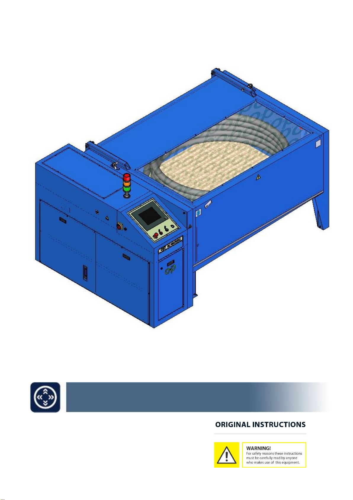
BC800/WES
( nome - name, tipo - type, modello - model / n° di serie - serial number )
• La macchina non rientra nell’elenco contenuto nell’All. IV della Direttiva Macchine 2006/42/CE
The machine is not part of the list included in Ann. IV Machinery Directive 2006/42/CE.
• La macchina rispetta i requisiti essenziali di sicurezza indicati sulla Direttiva Macchine e successive modifiche:
The machine follows the safety requirements included in the Machinery Directive and its following modifications:
2006/42/CE DIRETTIVA MACCHINE
2006/42/EC MACHINE DIRECTIVE
2014/35/EU DIRETTIVA BASSA TENSIONE
2014/35/UE LOW VOLTAGE DIRECTIVE (LVD)
2014/30/EU DIRETTIVA COMPATIBILITA’ ELETTROMAGNETICA
2014/30/UE ELECTROMAGNETIC COMPATIBILITY (EMC)
• La macchina è provvista di marcatura CE
The machine is provided with EC mark
• Norme di riferimento applicate:
Applied references normative:
UNI EN ISO 12100:2010 CEI EN 60204-1
IL LEGALE RAPPRESENTANTE
THE LEGAL REPRESENTATIVE
Brescia, lì DANIELE PIANTONI
(nome e firma o timbratura della persona autorizzata)
(name and signature or equivalent marking of authorized person)
Dichiariamo che il Fascicolo Tecnico è costituito presso OP s.r.l Via del Serpente 97, 25131 BRESCIA
We declare that the technical documentation is established c/o OP s.r.l. Via del serpente 97, 25131 BRESCIA
La persona responsabile del fascicolo tecnico è il Sig. Massimo Ziliani Resp. Uffi cio Tecnico.
Our technical manager, Mr. Massimo Ziliani, is responsible for the technical dossier

OP S.r.l. 25131 BRESCIA - Via Serpente, 97 - Tel. 030/3580401 - Fax 0303580838
⎯⎯⎯⎯⎯⎯⎯⎯⎯⎯⎯⎯⎯⎯⎯⎯⎯⎯⎯⎯⎯⎯⎯⎯⎯⎯⎯⎯⎯⎯⎯⎯⎯⎯⎯⎯⎯⎯⎯⎯
6

OP S.r.l. 25131 BRESCIA - Via Serpente, 97 - Tel. 030/3580401 - Fax 0303580838
⎯⎯⎯⎯⎯⎯⎯⎯⎯⎯⎯⎯⎯⎯⎯⎯⎯⎯⎯⎯⎯⎯⎯⎯⎯⎯⎯⎯⎯⎯⎯⎯⎯⎯⎯⎯⎯⎯⎯⎯
7
SAFETY REGULATIONS
1. Always make sure that the machine is placed on a stable, safe surface and that it is not
causing vibrations that, in addition to being bothersome and useless, may cause
malfunctions.
2.
Leave enough room in the work area.
3. The manufacturer is not liable for any damage caused by negligence.
4. Never use the equipment before reading the user manual and
understanding its contents
5. Caution! If improperly used, the equipment may be dangerous and may
cause injury to parts of the body, which must never come within the range
of moving parts.
6.
Test operations are safe provided the regulations given below are complied
with.
7. Caution! It is absolutely essential that all work is carried out
by one operator only
8. Never attempt to use the machine above the permitted working pressures; this might
cause serious danger to the operator
.
9. This manual must be given to the operator and kept. The proprietor of the equipment is
responsible for it. Ensure that the operator is aware of his responsibilities.
10. Never remove or tamper with guards.
11. Before connecting to the power supply, make sure that there is adequate protection
upstream of the connection against overloads and short circuits (it is advisable to have
protection against excessive undervoltage as well).
12. Check that the supply voltage and frequency correspond to the rating on the machine's
rating plate.
13. Use only cables, plugs and extension cables that comply with CEI standards; keep the
power cable far from the work zone.
14. Make sure that hoses are always tested in safety conditions
15.
Always remove the plug from the socket
, before performing any work on the machine.
Operations of maintenance, as well as repairs, should be performed by specialised
personnel.

OP S.r.l. 25131 BRESCIA - Via Serpente, 97 - Tel. 030/3580401 - Fax 0303580838
⎯⎯⎯⎯⎯⎯⎯⎯⎯⎯⎯⎯⎯⎯⎯⎯⎯⎯⎯⎯⎯⎯⎯⎯⎯⎯⎯⎯⎯⎯⎯⎯⎯⎯⎯⎯⎯⎯⎯⎯
8
16. Use adequate personal protection (gloves, appropriate clothing,
etc.).
17. Keep the supply cable far from the work zone.
18. Always turn off the machine while maintaining it
19. Use of the Crimping machine is permitted only to skilled adult staff (a training course is
recommended for those who have never used the equipment).
20. During work, always follow all instructions given by the labels on the machine
21. Our equipment is designed with the technical safety features required; customers are
advised to strictly comply with the instructions given in this manual.
22. Original spare parts must be used in order to maintain the original characteristics and
the validity of the certification.
23. Once you have finished maintenance operations always re-mount the eventually
removed protections before turning on the machine.
24. Use limit:
•The machine cannot be used in explosive settings.
•The machine cannot be used in outdoor settings.
•Do not leave the machinery exposed to environmental agents which do not meet into
protection level (IP55) of the installed components.
25. The machine presents residual risks derived from incorrect use: strictly follow the
directions defined in the use and maintenance manual.
26. Do not insert animals or body parts in the operating area or in moving parts.
27. Do not insert plastic, glass or other kinds of objects in the operating area or in moving
parts.
28. Do not make repairs yourself; contact the manufacturer.

OP S.r.l. 25131 BRESCIA - Via Serpente, 97 - Tel. 030/3580401 - Fax 0303580838
⎯⎯⎯⎯⎯⎯⎯⎯⎯⎯⎯⎯⎯⎯⎯⎯⎯⎯⎯⎯⎯⎯⎯⎯⎯⎯⎯⎯⎯⎯⎯⎯⎯⎯⎯⎯⎯⎯⎯⎯
9
READ INSTRUCTIONS FOR USE AND MAINTENANCE
USE OF THE MANUAL:
It is important to keep this manual near the machine where it can be consulted. The manual is
provided to give the user a general knowledge of the machine and instructions for its use and
maintenance as needed for satisfactory operation.
The manual, as required by the regulations in effect, is an integral part of the machine and
must accompany it for its entire lifetime. The instructions and warnings must be read with care
for safety reasons prior to installation and use. Do not make any changes in the manual, for
any reason, without the prior written authorisation of the manufacturer or authorised
distributor.
CAUTION:
The operator is personally responsible for respect, not only by himself but also by any others
who may be exposed to the hazards presented by the machine, of all safety rules.
Before performing any operation with the machine, therefore, read this manual carefully.
It describes the procedures for safe use. Keep the manual for future consultation.
The machine is constructed in a workmanlike manner. Its duration and reliability will be all the
more effective if the machine is used correctly and given regular maintenance.
The testing fluid “CUT-MAX H 05”, supplied by O+P, wholly respect the community norms on
the chemical products safety;
The disposal of the materials must be carried out in compliance with the laws in force.

OP S.r.l. 25131 BRESCIA - Via Serpente, 97 - Tel. 030/3580401 - Fax 0303580838
⎯⎯⎯⎯⎯⎯⎯⎯⎯⎯⎯⎯⎯⎯⎯⎯⎯⎯⎯⎯⎯⎯⎯⎯⎯⎯⎯⎯⎯⎯⎯⎯⎯⎯⎯⎯⎯⎯⎯⎯
10
CHARACTERISTICS OF THE BC 800/W ES TEST BENCH
MACHINE WITH NO HYDRAULIC FLUID OR SOLVENT
•Add hydraulic fluid with this characteristics:
- viscosity at 40°C : 40 mm²/s
- suggested contamination class : ISO 4406 20/18/15
- fluid quantity : as shown in table below
•For the characteristics of the solvent see the attached document
(CHARACTERISTICS AND SAFETY DATA SHEET OF CUT-MAX H
05)
This test bench has been designed to perform high-pressure tests on hydraulic hoses.
It is equipped with user-friendly control panel, and can be ordered customised with special
instruments. Special care has been dedicated to the safety devices; tests can only be carried
out with the testing chamber closed, and it cannot be accessed as long as there are
pressurised components in the circuit.
Filling stage: a low pressure pump fills the hydraulis hose so as to eliminate all the air, after
which the outlet is blocked and the pressure in the circuit begins to rise until it reaches the set
value, holding the circuit at that pressure with minimum consumption.
The test bench is designed and produced in respect of the essential health and safety rules set
forth by the machine directive. In particular, since the operator comes directly into contact with
the machine we have done our best to:
•Eliminate sharp edges and points.
•See that the controls, though ensuring prompt, safe and univocal action, do not involve any
additional hazards: actions can only occur by voluntary use of the controls.
SAFETY DEVICES: The test bench mounts some safety device to prevent the entrance in the
chamber during the test operations.
Furthermore there is an emergency stop system to halt immediately the test, if necessary.
Besides a pressure regulator on the pneumatic circuit maintains the multiplier action into the
desired pressure range.

OP S.r.l. 25131 BRESCIA - Via Serpente, 97 - Tel. 030/3580401 - Fax 0303580838
⎯⎯⎯⎯⎯⎯⎯⎯⎯⎯⎯⎯⎯⎯⎯⎯⎯⎯⎯⎯⎯⎯⎯⎯⎯⎯⎯⎯⎯⎯⎯⎯⎯⎯⎯⎯⎯⎯⎯⎯
11
Briefly, the machine consists of:
A metal structural work supporting the testing chamber, which contains the air-hydraulic
pump that acts as a pressure booster and the entire system for adjustment and control of
the air-hydraulic system. There is also a useful compartment for accessories in the front
panel.
A testing chamber fitted with transparent Lexan screens allowing visual monitoring of the
operations, holds two manifolds on the inside, which serve for testing hydraulic hoses, that
make it extremely simple to prepare for testing. The manifolds are positioned and fixed on
the left side of the chamber.
WARNING: Please replace the protection panel should you notice cracks thereon.
For this task contact the Manufacturer or their Agent.
Pressure multiplier and fluidodynamic circuit: this is the core of the test system and is
composed of electro-pneumatic controls and by the pneumo-hydraulic pressure booster; the
multiplication ratio between the inlet air pressure and the outlet liquid pressure is about
1:226. The fluid used for the tests is “CUT-MAX H 05”. The Technical Data Sheet for this
product is enclosed with the instruction booklet listing all the technical features of the fluid
used.
Control panel: this panel can be used to set tests, test pressure, test time, test time and
duration of air purging operation from part to be tested; this panel can also be provided with
customized features for special needs.
TECHNICAL / DIMENSIONAL DATA
BC 800/W ES
Testing chamber dimensions (WxDxH)
1900 x 1500 x 750 mm
Overall dimensions (WxDxH)
2620 x 1780 x 1530 mm
Weight
965 Kg ≈
Pressure multiplication ratio
1:226
Standard maximum testing pressure
800 bar
Instrumentation
Electric
Mains voltage
400V 50Hz 3phase
Maximum air input pressure
8 bar
Minimum air delivery rate required
1500 Nlt/min
Filling phase pump delivery rate
25 lt/min
Liquid tank capacity
250 lt
Degree of filtration
25 µ
Drive
Electric
Electric motor
2 HP B5 4P 400V 50Hz 3phase

OP S.r.l. 25131 BRESCIA - Via Serpente, 97 - Tel. 030/3580401 - Fax 0303580838
⎯⎯⎯⎯⎯⎯⎯⎯⎯⎯⎯⎯⎯⎯⎯⎯⎯⎯⎯⎯⎯⎯⎯⎯⎯⎯⎯⎯⎯⎯⎯⎯⎯⎯⎯⎯⎯⎯⎯⎯
12
HANDLING / TRANSPORT
WARNING
The personnel in charge of handling and transportation must pay the utmost
attention in order to avoid the test bench to be submitted to shocks or stresses
that would jeopardize the proper functioning of the machine, and safety of the
operator.
The machine is transportable without disassembling it. In any case, it is important to pay
attention to the following precautions:
In case the machine is transported, or moved, it is suggested to lift it from the bottom side by
using the proper spaces located below the test chamber.
We suggest to be very careful because, since the machine, being long and narrow, can result
to be unstable.
If the machine has to be shipped, ensure that it is firmly secured to the means of transport and
protected against knocks, vibrations or shaking.
LIGHTING:
The bench is provided with one light fixtures that ensure good visibility of the inside of the
chamber. The light go on when the master switch is turned on.
WARNING: Always make sure that the machine is placed on a stable, safe surface and that it
is not causing vibrations that, in addition to being bothersome and useless, may cause
malfunctions.
If the test bench is not placed on a stable and levelled surface, the bench door
might not open.

OP S.r.l. 25131 BRESCIA - Via Serpente, 97 - Tel. 030/3580401 - Fax 0303580838
⎯⎯⎯⎯⎯⎯⎯⎯⎯⎯⎯⎯⎯⎯⎯⎯⎯⎯⎯⎯⎯⎯⎯⎯⎯⎯⎯⎯⎯⎯⎯⎯⎯⎯⎯⎯⎯⎯⎯⎯
13
PLATES AND WARNING SIGNS:
The machine is provided with warning signs and instructions that the operator must obey for
his own health and safety. If signs are deteriorated and not well readable, it is necessary to
substitute them with new plates.
LIMBS CRUSHING GENERIC HAZARD EYE PROTECTION HEARING PROTECTION
PREVENTIVE MAINTENANCE:
WARNING:
Always remove the plug from the socket, before performing any work on the
machine.
•Always, before using the test bench, check the conditions of the safety devices,
connections, and hydraulis hoses. Check for oil leaks and other problems.
•Check for wear and legibility of the warning signs.
•Periodically, check the hydraulis hoses connecting to the central unit and relative
couplings, and replace or repair any that need it.
•In case of bursting of the tested component, check that all the safety protections are
not damaged.
•Periodically check that filters are not blocked. If necessary proceed with the substitution
of the filtering cartridge.

OP S.r.l. 25131 BRESCIA - Via Serpente, 97 - Tel. 030/3580401 - Fax 0303580838
⎯⎯⎯⎯⎯⎯⎯⎯⎯⎯⎯⎯⎯⎯⎯⎯⎯⎯⎯⎯⎯⎯⎯⎯⎯⎯⎯⎯⎯⎯⎯⎯⎯⎯⎯⎯⎯⎯⎯⎯
14
ROUTINE MAINTENANCE –GENERAL REGULATIONS
WARNING:
Always remove the plug from the socket, before performing any work on the
machine.
•It is important for all operations on the machine to be carried out by qualified, authorised
personnel, familiar with its functions.
•Never perform any operations of cleaning, lubrication or maintenance with the machine in
motion.
•We recommend wearing safety apparel such as non-skid footwear, earplugs, goggles,
suitable gloves, etc.
•After terminating all operations, always re-mount any guards removed before starting the
machine.
•For best results in operation of the booster pump, it is essential to use filtered but not
lubricated air; the test bench is equipped with an air preparation unit, located just past the
compressed air intake outlet, this unit must be kept constantly under control (for lubrication
of the pneumatic parts we recommend using oil TELLUS SHELL 22 or the equivalent). The
regulator of this unit has already been calibrated by O+P, for safety reasons;
any
readjustment could jeopardise proper operation of the test bench or create a hazardous
situation.
•Periodically, clean or replace, if necessary, the filters for the system fluid; the drain filter is
mounted on the lid of the tank. Loosen the fastening screws to access it, remove the lid on
the filter and take the filter cartridges out. The system is provided with two additional filters,
immersed in the tank, mounted on the pump intake circuit; to clean them, take the lid off
the tank. The filters have a filtration power of 60 in intake and 25 µ on outlet.
•Replace the fluid filter, located over the tank (see pneumohydraulic diagram, position 3),
every two or three months or as necessary.
•Check and replace the fluid (CUT-MAX H 05 5) for testing when it becomes too polluted. A
drain tap is located on the side of the tank.
•Frequently check the conditions of the emergency stop on the control panel and safety
devices for closure of the tank door.
•For any operations of maintenance on the booster pump, see the enclosed instruction
manual.
SPARE PARTS
Accessories, spare parts or consumable materials must be ordered from O+P, always
specifying the serial number and model; these data will be found on the test bench nameplate.
Contact our sales office for detailed information.

OP S.r.l. 25131 BRESCIA - Via Serpente, 97 - Tel. 030/3580401 - Fax 0303580838
⎯⎯⎯⎯⎯⎯⎯⎯⎯⎯⎯⎯⎯⎯⎯⎯⎯⎯⎯⎯⎯⎯⎯⎯⎯⎯⎯⎯⎯⎯⎯⎯⎯⎯⎯⎯⎯⎯⎯⎯
15
CONTROL PANEL
-PICTURE 1 –

OP S.r.l. 25131 BRESCIA - Via Serpente, 97 - Tel. 030/3580401 - Fax 0303580838
⎯⎯⎯⎯⎯⎯⎯⎯⎯⎯⎯⎯⎯⎯⎯⎯⎯⎯⎯⎯⎯⎯⎯⎯⎯⎯⎯⎯⎯⎯⎯⎯⎯⎯⎯⎯⎯⎯⎯⎯
16
01 –“LINE” INDICATOR LIGHT
Lights to indicate that the control panel is on.
02 –"EMERGENCY” STOP BUTTONS
When a red mushroom-head button is pressed, the power supply is cut off and the pump
stops immediately; to restart operation, first release the button by turning it in the
direction shown by the arrow, then press the “START” button again.
03 –“STOP” BUTTON
Press to stop test. Press to stop the cycle and draining the pressure.
04 –“START ” BUTTON
Press this button after preparing the machine and making the settings (see
INSTRUCTIONS FOR USE on page 25) to start the test.
05 –BUTTON "DOOR OPENING"
Press this button to open the door.
06 –BUTTONS “DOOR CLOSING”
Press these buttons to close the door.
07 –“MASTER SWITCH” (Beside the frame unit)
Turn “ON” to connect the machine to the power supply.
08 –“TOUCH SCREEN CONTROL PANEL”permits setting tests, cycle times, number of
cycles and duration of air bleeding from the components being tested; this panel can be
customised for specific requirements.
09 –SIGNALLING LAMP which indicates the current state of operations.
10 –“BI-MANUAL CONTROL DESK”.

OP S.r.l. 25131 BRESCIA - Via Serpente, 97 - Tel. 030/3580401 - Fax 0303580838
⎯⎯⎯⎯⎯⎯⎯⎯⎯⎯⎯⎯⎯⎯⎯⎯⎯⎯⎯⎯⎯⎯⎯⎯⎯⎯⎯⎯⎯⎯⎯⎯⎯⎯⎯⎯⎯⎯⎯⎯
17
PRELIMINARY CHECKS AND START-UP
1) Make sure the quantity of testing fluid in the tank is enough while checking the relative
level indicator; otherwise, see to the refill as explained in the following procedure:
How to fill up with testing fluid
•Remove the side panel
•Remove the cap shown in the picture below and fill up the tank with the fluid
•Put the cap back in its position.
•Put the side panel back in its position and fix it using the screws on the panel.
2) Make sure that the power supply is correct and connect the plug (pic. 3 item 01);
3) Connect the test bench to the air supply (pic. 3 item 02). For optimum bench operation,
the air flow-rate available must be of 1500 Nlt/min, with a pressure of 8 bar and the
pneumatic part of the circuit must always be pressurised.
1
2

OP S.r.l. 25131 BRESCIA - Via Serpente, 97 - Tel. 030/3580401 - Fax 0303580838
⎯⎯⎯⎯⎯⎯⎯⎯⎯⎯⎯⎯⎯⎯⎯⎯⎯⎯⎯⎯⎯⎯⎯⎯⎯⎯⎯⎯⎯⎯⎯⎯⎯⎯⎯⎯⎯⎯⎯⎯
18
INSTRUCTIONS FOR USE (testing cycle)
Before starting prefitting operations, read the following sections very carefully:
•MACHINE CHARACTERISTICS
•ROUTINE MAINTENANCE
•SAFETY REGULATIONS
•CONTROLS
•PRELIMINARY CHECKS / START-UP
•LIGHTING
For instructions on controls and adjustments, refer to the "CONTROL PANEL" section.
1. Turn the “Master Switch”(pic.1 pos.07).
2. Open the chamber door with “Opening door” button (pic1. pos.05).
3. Connect the hydraulic hose or components to testing with the connections provided on
the manifolds (pic.2, item 1), using adapters if needed.
4. Close the chamber door with “Closing door” buttons (pic1. pos.06).
5. Enter the test pressure through the control panel (pic1. pos.08);
IMPORTANT:
no air should remain inside the test pipe
,
therefore it is essential to set
the time for filling with fluid correctly, using the appropriate timer.
6. Select the test mode,
testing parameters
.. If testing by impulses, set the number of
cycles and regulate the pause and work time.
7. Press the
“Start”
button (pic.1 pos.04). The chamber door being locked and the test can
begins with the setted parameters; if any problems should arise during this stage, stop
the test immediately by pressing the “E
mergency Stop”
button (pic.1 pos.02).
8. Press the
“Stop”
button (pic.1 pos.03) to stop the test (static test), or wait until the set
number of cycles has been reached (impulse testing). After a very short time, to allow
the liquid to drain, the tank door can be opened and the component removed. For
safety, check that the
digital pressure gauge
s shows that there is no pressure present
before opening.
CAUTION: THE OPERATOR MUST BE VERY CAREFUL AND USE EXTREME CAUTION WHEN OPENING
AND CLOSING THE DOORS INSTALLED ON THE MACHINE, SINCE THIS OPERATION INVOLVES THE
RISK OF CRUSHING THE UPPER LIMBS.
CAUTION: IT IS VERY IMPORTANT TO VENT COMPLETELY THE COMPONENT BEFORE TESTING.
THEREFORE IT IS NECESSARY THAT THE FLUID FILLING TIME BE SET CORRECTLY.
CAUTION: TO OPERATE CORRECTLY, THE TWO MANIFOLDS MUST ALWAYS BE CONNECTED
EACH OTHER, THEREFORE IT ISN’T POSSIBLE TEST A PIECE WITH ONLY ONE
CONNECTION.

OP S.r.l. 25131 BRESCIA - Via Serpente, 97 - Tel. 030/3580401 - Fax 0303580838
⎯⎯⎯⎯⎯⎯⎯⎯⎯⎯⎯⎯⎯⎯⎯⎯⎯⎯⎯⎯⎯⎯⎯⎯⎯⎯⎯⎯⎯⎯⎯⎯⎯⎯⎯⎯⎯⎯⎯⎯
19
MANIFOLDS DIAGRAM
-PICTURE 2 -

OP S.r.l. 25131 BRESCIA - Via Serpente, 97 - Tel. 030/3580401 - Fax 0303580838
⎯⎯⎯⎯⎯⎯⎯⎯⎯⎯⎯⎯⎯⎯⎯⎯⎯⎯⎯⎯⎯⎯⎯⎯⎯⎯⎯⎯⎯⎯⎯⎯⎯⎯⎯⎯⎯⎯⎯⎯
20
CONNECTION DIAGRAM
-PICTURE 3 -
01 - Plug for electricity: connect to the power supply.
02 - Connector for air supply: connect to compressed air.
Table of contents
Other OP Industrial Equipment manuals
Popular Industrial Equipment manuals by other brands

Seneca
Seneca S117P1 installation manual

PIETRO FIORENTINI
PIETRO FIORENTINI Dival 600 user manual

BVA Hydraulics
BVA Hydraulics CL05A instruction manual

schmersal
schmersal AZM300Z-ST-1P2P-T Instructions for operation

Cyber-Tech
Cyber-Tech mechanical Joysticks JS-2050-HD Series quick start guide

CHERNE
CHERNE JET-BALL 254-207 instructions

Sulzer
Sulzer EWK manual

Siemens
Siemens 8GK6430 - 4KK24 operating instructions

RUD
RUD VCGH-S Safety instruction

Ingersoll-Rand
Ingersoll-Rand Doosan XHP1070CM-1800 Operation Maintenance & Parts Manual

Advantech
Advantech PWS 472 Startup manual

Taco Electronic Solutions
Taco Electronic Solutions iWorx MPU2 Application guide