Opentrons Thermocycler Module GEN2 User manual

Opentrons Labworks Inc.
January 2024
Thermocycler GEN2
Instruction Manual

Table of Contents
Product and Manufacturer Description 3
- Product Description
- Manufacturer Description
Safety Information and Regulatory Compliance 4
-SafeUseSpecications
- Safety Warning Labels
- Instrument Safety Warnings
- Standards Compliance
ProductSpecications11
- Model Number
- Included Parts
-PhysicalSpecications
-TemperatureProle
- LED Status Light
- Emergency Lid Opening
- Deck Placement and Cable Alignment
BeforeYouBegin 14
- Flex Caddies
- Anchor Adjustments
- Ventilation Clearance
FlexInstallationSteps 18
- Attaching the Thermocycler
- Calibrating the Thermocycler
OT-2 Attachment Steps 20
Attaching the Rubber Automation Seal 22
Maintenance 23
Cleaning 23
Additional Product Information 25
- Warranty
- Support
- App Download

THERMOCYCLER MODULE GEN2
3
Product and Manufacturer Description
PRODUCT DESCRIPTION
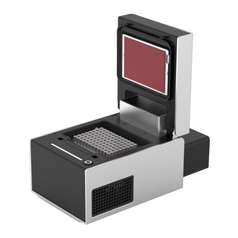
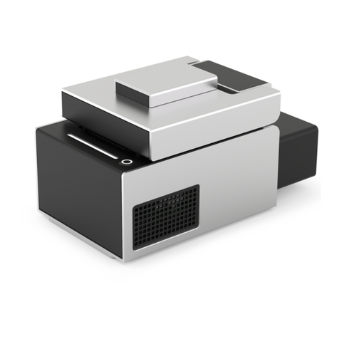
The Opentrons Thermocycler Module GEN2 is a fully automated
on-deck thermocycler, providing hands-free PCR in a 96-well plate
format.Itsheatedlidanddisposablesealttightlyovertheplate,
ensuringefcientsampleheatingandminimalevaporation.
MANUFACTURER DESCRIPTION
Opentrons Labworks Inc
45-18 Ct Square W
Long Island City, NY 11101

THERMOCYCLER MODULE GEN2
4
Safety Information and Regulatory Compliance
Opentrons recommends that you follow the safe use specications
listed in this section and throughout this manual.
SAFE USE SPECIFICATIONS
Input and Output Connections
The Thermocycler has the following power input requirements,
which are met by the included power supply.
Warning:Do not replace the power supply cable
unless at the direction of Opentrons Support.
Power supply (AC):
� Voltage: 100–240 V
�Frequency: 50/60 Hz
�Current: 8.5–5 A
�Overvoltage: Category II
Environmental Conditions
The Thermocycler should only be used indoors on a sturdy, dry,
athorizontalsurface.Itmustbeinstalledinalow-vibration
environment with stable ambient conditions. Keep the Thermocycler
away from direct sunlight or HVAC systems that may cause
signicanttemperatureorhumiditychanges.
Note: The Thermocycler should not be powered
on or used in conditions outside of the acceptable
operating conditions.

THERMOCYCLER MODULE GEN2
5
Thefollowingtablelistsanddenesstandardsfor
recommended use, acceptable use, and storage.
Environmental
Conditions
Recommended Acceptable Storage and
Transportation
Ambient
Temperatures
+20 to +25 °C +2 to +40 °C –10 to +60 °C
Relative Humidity 30–80%, non-
condensing
30–80%, non-
condensing
(below 30 °C)
10–85%, non-
condensing
(below 30 °C)
Altitude Approximately 500
m above sea level
Up to 2000 m
above sea level
Up to 2000 m
above sea level
Operating Conditions Description
Recommended Opentrons has validated the Thermocycler’s
performance in the conditions
recommended for system operation.
Operating the Thermocycler in these
conditions helps provide optimal results.
Acceptable The Thermocycler is safe to use in
conditions acceptable for system operation,
but results may vary.
Storage Storage and transportation conditions
only apply when the device is completely
disconnected from power and other
equipment.
Thefollowingtablelistsanddenestheenvironmentaloperating
conditions for recommended use, acceptable use, and storage of
your Thermocycler.

THERMOCYCLER MODULE GEN2
6
Low Temperature Condensation
Setting the Thermocycler to hold a temperature below the ambient
temperature for a long time can cause condensation to develop in
and on the device.
Warning: Do not set the plate temperature below
the ambient temperature for over two hours, as
the resulting condensation could affect performance
or damage the module.
If you notice condensation on the Thermocycler’s plate after use,
remove any labware from the module. Use the Opentrons App to set
a temperature of 40 °C until the condensation is no longer visible.
Software requirements
The Thermocycler requires version 6.2.0 (or higher) of the Opentrons
App and robot software. You can download the Opentrons App for
Mac, Windows, or Linux at https://opentrons.com/ot-app.
Labware Compatibility
The Thermocycler is compatible with full-skirted, 96-well PCR
plates.PerformancespecicationsarebasedonusewithOpentrons
Tough PCR Plates, which you can purchase at
https://shop.opentrons.com.

THERMOCYCLER MODULE GEN2
7
SAFETY WARNING LABELS
Warning symbols posted on the Opentrons Thermocycler and in
this manual warn you about sources of potential injury or harm. The
followingtablelistsanddeneseachsafetywarningsymbol.
Symbol Description
CAUTION: Risk of danger!
Thissymbolidentiesinstrumentcomponentsthatposea
risk of personal injury or instrument damage if improperly
handled. Wherever this symbol appears, please consult
the manual for further information on safe handling
before proceeding.
CAUTION: Risk of electrical shock!
Thissymbolidentiesinstrumentcomponentsthatposea
risk of electrical shock if handled improperly.
CAUTION: Hot surface!
Thissymbolidentiesinstrumentcomponentsthatposea
risk of burning or heat damage if handled improperly.
CAUTION: Pinch point!
Thissymbolidentiesinstrumentcomponentswhichcan
pose a risk of personal injury due to a closing mechanism.
Please do not touch the lid while it is in operation.
CAUTION: Risk of explosion!
Thissymbolidentiesinstrumentcomponentsthatposea
risk of creating an explosion if handled improperly.

THERMOCYCLER MODULE GEN2
8
INSTRUMENT SAFETY WARNINGS
Warning symbols posted on the Opentrons Thermocycler refer
directly to the safe use of the instrument. Refer to the previous table
forsymboldenitions.
Symbol Description
CAUTION: Warning about risk of harm to body or
equipment. Operating the Opentrons Thermocycler
before reading this manual poses a risk of personal
injuryorinstrumentdamage.Onlyqualiedlaboratory
personnel should operate this equipment.
CAUTION: Warning about risk of harm to body or
equipment from electrical shock. Do not attempt
to repair or remove the outer case of the Opentrons
Thermocycler or its power supply unless directed by
Opentrons Support. Attempting to do so puts you at risk
of electrical shock.
CAUTION: Warning about risk of burning.
The Opentrons Thermocycler generates enough heat to
cause serious burns. Wear safety goggles or other eye
protection at all times during operation. Always ensure the
sample block returns to idle temperature before opening
the lid and removing samples. Always allow maximum
clearance to avoid accidental burns. The seal on the lid
can also be hot when opened. Unplug the unit after use,
if possible.
CAUTION: Warning about moving parts.
The lid on the Opentrons Thermocycler presents a pinch
pointhazard.Keephandsandngersawayfromthe
module while the lid is opening or closing.
CAUTION: Warning about risk of explosion.
Do not operate the Opentrons Thermocycler in areas used
for working with explosive substances. Do not process
explosive or highly reactive materials in the module or use
it with substances that could generate explosive gases.

THERMOCYCLER MODULE GEN2
9
STANDARDS COMPLIANCE
The Thermocycler has been tested and found to be in compliance
with all applicable requirements of the following safety and
electromagnetic standards.
Safety
�IEC/UL/CSA 61010-1 Safety Requirements for Electrical
Equipment for Measurement, Control, and Laboratory
Use–Part 1: General Requirements
�IEC/UL/CSA 61010-2-010 Particular Requirements for
Laboratory Equipment for the Heating of Materials
Electromagnetic Compatibility
�EN/BSI 61326-1 Electrical Equipment for Measurement,
Control and Laboratory Use–EMC Requirements–Part 1:
General Requirements
�EN55011Industrial,ScienticandMedicalEquipment–Radio
Frequency Disturbance Characteristics–Limits and Methods
of Measurement
�FCC 47CFR Part 15 Subpart B Class A: Unintentional Radiators
�IC ICES–003 Spectrum Management and Telecommunications
Interference Causing Equipment Standard–Information
Technology Equipment (Including Digital Apparatus)

THERMOCYCLER MODULE GEN2
10
FCC Warnings and Notes
Warning: Changesormodicationstothisunitnot
expressly approved by Opentrons could void the
user’s authority to operate the equipment. This device
complies with part 15 of the FCC Rules. Operation is
subject to the following two conditions:
This device may not cause harmful interference.
This device must accept any interference received,
including interference that may cause undesired
operation.
Note: This equipment has been tested and found to
comply with the limits for a Class A digital device,
pursuant to part 15 of the FCC rules. These limits
are designed to provide a reasonable protection
against harmful interference when the equipment
is operated in a commercial environment. This
equipment generates, uses, and can radiate radio
frequency energy and, if not installed and used in
accordance with the instruction manual, may cause
harmful interference to radio communications.
Operation of this equipment in a residential area is
likely to cause harmful interference in which case the
user will be required to correct the interference at
their own expense.
Canada ISED
Canada ICES–003(A) / NMB–003(A)
This product meets the applicable Innovation, Science and
EconomicDevelopmentCanadatechnicalspecications.
CISPR11ClassA
Caution: This equipment is not intended for use in residential
environments and may not provide adequate protection to radio
reception in such environments.

THERMOCYCLER MODULE GEN2
11
Product Specifications
MODEL NUMBER
TCG2
INCLUDED PARTS
Heated Lid and
Seal System
Automated Lid LED Strip
Seal Compression
Mechanism
Exhaust
Duct
Air Intake Vents
Well Plate Block
Plate Lift Mechanism
(1)Thermocycler
(1)PowerCable
(5) Rubber Automation
Seals
(1)PowerSupplyand
Power Supply Connector
(1)USBCable
(10)OpentronsTough
PCR Plates
Lid/Plate Lift Button

THERMOCYCLER MODULE GEN2
12
PHYSICAL SPECIFICATIONS
Dimensions with lid open 244.95 mm L x 172 mm W x 310.1 mm H
Dimensions with lid closed 244.95 mm L x 172 mm W x 170.25 mm H
Weight 8.4 kg (including rear duct)
TEMPERATURE PROFILE
Thermal Block �Range: 4–99 °C
�Maximum heating ramp rate: 4.25 °C/s from
ambient to 95 °C
�Maximum cooling ramp rate: 2.0 °C/s from 95 °C
to ambient
Lid �Range: 37–110 °C
�Accuracy: ±1 °C
LED STATUS LIGHT
The Thermocycler has a strip of LEDs that can display four colors:
white, orange, red, and blue. The possible module conditions
indicated by the light are listed below.
LED Color and Behavior Module Conditions
Solid white Idle
Flashing orange Error
Pulsing red Changing to hot temperature (>23 °C)
Solid red Holding at hot temperature (>23 °C)
Pulsing blue Changing to cool temperature (<23 °C)
Solid blue Holding at cool temperature (<23 °C)

THERMOCYCLER MODULE GEN2
13
Warning: The status LED displays solid white whenever
the module is not actively heating or cooling, regardless
of its current temperature. Handle with caution. The
module may still be hot to the touch.
EMERGENCY LID OPENING
In case of a power outage, connectivity issue, or other electrical
failure, the Thermocycler lid may not open. Follow these steps to
manually open the lid:
1. If possible, turn the unit off and unplug it.
2. Insert the included hex wrench into the circular slot on the left
side of the module.
3. Push the wrench inward 25 mm / 1 inch.
4. Lift the lid manually.

THERMOCYCLER MODULE GEN2
14
Before You Begin
Review this section for important information about deck
placement, alignment, and anchor adjustments for the Thermocyler.
FLEX CADDIES
WhenusedwithaFlexrobot,theThermocyclertsintoacaddy
that occupies space below the deck. The caddy places your
labware closer to the deck surface and allows for below-deck
cable routing. See the Modules chapter in the Flex Instruction
Manual for more information.
The OT-2 does not use caddies. Modules clip directly to the deck.
Also, the Thermocycler ships with a short exhaust duct, which is
usedbytheOT-2only.Themodulewillnottproperlyinitscaddy
with the OT-2 duct attached.
Module caddies are available for purchase at shop.opentrons.com.
Exhaust Duct
Cable
Management
Bracket
Handles
Anchors

THERMOCYCLER MODULE GEN2
15
ANCHOR ADJUSTMENTS
Anchors are screw-adjustable panels on the Thermocycler caddy.
They provide the clamping force that secures the module to its
caddy. Use a 2.5 mm screwdriver to adjust the anchors.
�To loosen/extend the anchors, turn the screws
counterclockwise.
�To tighten/retract the anchors, turn the screws clockwise.
Before installation:
�Check the anchors to make sure they’re level or extend slightly
past the sides of the caddy.
�If the anchors interfere with installing the module, adjust them
until there’s enough clearance to seat the module and then
tighten them to hold it in place.

THERMOCYCLER MODULE GEN2
16
DECK PLACEMENT AND CABLE ALIGNMENT
The supported deck slot positions for the Thermocycler depend on
the robot you’re using.
Robot Model Deck Placement
Flex Requires deck slots A1, B1,
and the A1 expansion slot.
OT-2 Requires deck slots 7, 8, 10, and 11.
To properly align the module relative to the robot, make sure its
exhaust port faces to the rear (away from the center of the deck).
This keeps the exhaust port clear and aligns the power and USB
ports to the left side of the robot for easy access.
VENTILATION CLEARANCE
The Flex and OT-2 need at least 20 cm (8") of side and back
clearance. This space helps dissipate exhaust from
the Thermocycler.
8”
20 cm
FRONT

THERMOCYCLER MODULE GEN2
17
For OT-2 ventilation, Opentrons recommends using the side and rear
window panels shown below. These panels are included with newer
OT-2 models. If you have an older OT-2 and need these panels,
contact us at support@opentrons.com.
2x Side Panels 1x Rear Panel

THERMOCYCLER MODULE GEN2
18
Flex Installation Steps
Setting up the Thermocycler on your robot includes attaching it to
thedeckandrunningarst-timecalibrationprocess.The
instructions here and on the touchscreen will help you get started.
The tools you need are included in the User Kit that came with
your Flex.
ATTACHING THE THERMOCYCLER
Use a 2.5 mm hex screwdriver to remove the A1 expansion
slot plate and the A1 and B1 deck slot plates.
Using both hands, lift the module carefully and insert it into
its caddy. Make sure the module’s exhaust port faces the
exhaust duct on the caddy.
Use a 2.5 mm hex screwdriver to turn the anchor screws
clockwise to tighten the anchors. The module is secure when
it doesn’t move while gently pulling on it and rocking it from
side to side.
Connect the USB cable to the module and route the
remaining cable through the cable management bracket.
Connect the power connector to the module by pressing it
rmlyintoplace.Routetheremainingcablethroughthecable
management bracket.
Insertthecaddy,exhaustductrst,intotheopendeckslot.
Route the USB and power cables through the removable side
covers as you lower the caddy into position.
Connect the USB cable to a USB port on the Flex.
Connect the power cable from the module to the external
power supply unit. Manually tighten the locking ring to
secure it to the power supply.
Connect the power supply to a wall outlet and turn on the
power supply.
If you see a white light on the Thermocycler, it is powered on.
You can press the illuminated button to open and close the lid.
1
2
3
4
5
6
7
8
9

THERMOCYCLER MODULE GEN2
19
When successfully connected, the module appears in the
Pipettes and Modules section on your robot’s device detail
page in the Opentrons App.
Next, you’ll calibrate the module.
CALIBRATING THE THERMOCYCLER
You need to calibrate the Thermocycler after attaching it for the
rsttime.TocalibratetheThermocycler,turnonthepowersupply.
Thisstartsthecalibrationworkowprocessonthetouchscreen.
Instructions on the touchscreen will take you through a guided
workowprocess,whichisalsooutlinedbelow.
Warning: The gantry and pipette will move during
calibration. Keep your hands clear of the working area
before tapping an action button on the touchscreen.
Tap Start setup on the touchscreen. The robot checks the
module’srmwareandupdatesitautomatically,ifrequired.
Attach the module’s calibration adapter and tap
Conrmplacement.
Attach the calibration probe to the indicated pipette.
Tap Begin calibration.
After the calibration process is complete, remove
the calibration block from the module and remove the
calibration probe from the pipette.
Click Exit.
Your module is now calibrated. You will not have to recalibrate the
same module if you remove and reattach it to the same Flex.
1
2
3
4
5
6

THERMOCYCLER MODULE GEN2
20
OT-2 Attachment Steps
To attach the Thermocycler to your OT-2:
Use a 2.5 mm hex screwdriver or L-key to attach the exhaust
duct to the back of the module. Use the two included
screws, one on either side of the duct.
Using both hands, lift the module carefully, set it in its
supported deck location and press gently into place.
Connect the USB cable to the module. Route the remaining
cable through the cable management bracket and connect
the other end of the USB cable to a USB port on the OT-2.
Connect the power connector to the module by pressing
itrmlyintoplace.Routetheremainingcablethroughthe
side window.
Connect the power cable to the power supply unit.
Connect the power supply to a wall outlet.
Turn on the Thermocycler power supply.
1
2
3
4
5
6
7
Other manuals for Thermocycler Module GEN2
2
Table of contents
Other Opentrons Laboratory Equipment manuals
Popular Laboratory Equipment manuals by other brands

Metrohm
Metrohm 873 Biodiesel Rancimat manual

vacuubrand
vacuubrand PC 2001 Vario Instructions for use

PolyScience
PolyScience MX07R-20 Operator's manual

Thermo Scientific
Thermo Scientific MaxQ 7000 user manual

Millipore Sigma
Millipore Sigma SNAP i.d. 2.0 user guide

Gossen MetraWatt
Gossen MetraWatt SECULIFE UP operating manual