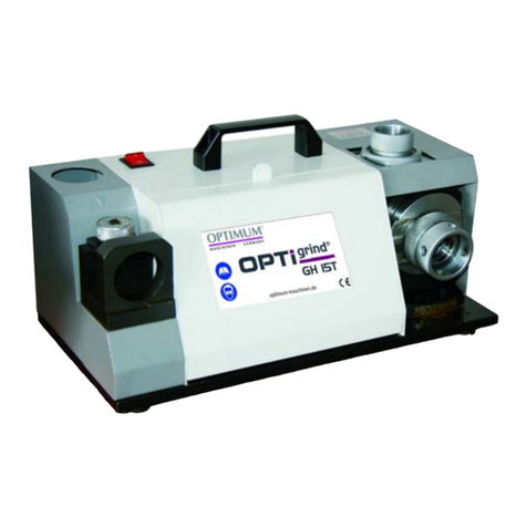
Optimum OptiGrind GH 10T User manual

EN
310 0110 310 0115
Operating manual
Version 1.1.4
Drill bit grinder

Version 1.1.4 dated 2022-09-23Page 2 Translation of the original instructions
GH 10T | GH 15TEN
Table of contents
1 Safety
1.1 Representation Conventions ...................................................................................................................4
1.2 Safety instructions (warning notes) ..........................................................................................................4
1.2.1 Classification of hazards ..............................................................................................................4
1.2.2 Other pictograms ..........................................................................................................................5
1.3 Intended use ............................................................................................................................................5
1.4 Possible dangers caused by the drill bit grinder ......................................................................................6
1.5 Qualification of the staff ...........................................................................................................................6
1.5.1 Target group .................................................................................................................................6
1.5.2 Authorized personnel ...................................................................................................................7
1.6 Operator positions ...................................................................................................................................8
1.7 Safety measures during operation ...........................................................................................................8
1.8 Safety devices .........................................................................................................................................8
1.9 Safety check ............................................................................................................................................8
1.10 Safety during operation ............................................................................................................................9
1.11 Accident report .........................................................................................................................................9
2 Technical data
2.1 Electrical connection ..............................................................................................................................10
2.2 Speed ....................................................................................................................................................10
2.3 Grinding disc ..........................................................................................................................................10
2.4 Collect chuck seat ..................................................................................................................................10
2.5 Point angle .............................................................................................................................................10
2.6 Grinding capacity ...................................................................................................................................10
2.7 Dimensions ............................................................................................................................................10
2.8 Environmental conditions .......................................................................................................................10
2.9 Emissions ..............................................................................................................................................10
2.10 Dimension grinding discs .......................................................................................................................11
3 Assembly
3.1 Scope of delivery ...................................................................................................................................12
3.2 Storage ..................................................................................................................................................12
3.3 Installation ..............................................................................................................................................12
3.3.1 Requirements regarding the installation site ..............................................................................13
3.4 Suction ...................................................................................................................................................13
4Operation
4.1 Safety .....................................................................................................................................................14
4.2 Overview ................................................................................................................................................14
4.3 Application range of coated grinding wheels .........................................................................................14
4.4 Regrinding spiral drill .............................................................................................................................15
4.4.1 Mounting clamping chuck groups ...............................................................................................15
4.4.2 Setting the spiral drill ..................................................................................................................17
4.5 Additional types of grinding on the twist drill ..........................................................................................20
4.5.1 Creating Form A .........................................................................................................................21
4.6 Drill geometry .........................................................................................................................................22
5 Malfunctions
6 Maintenance
6.1 Safety .....................................................................................................................................................25
6.1.1 Preparation .................................................................................................................................25
6.1.2 Restarting ...................................................................................................................................25
6.2 Inspection and maintenance ..................................................................................................................25
6.3 Repairs ..................................................................................................................................................25
6.4 Replacing of the grinding disc ................................................................................................................26
6.5 Fuse exchange ......................................................................................................................................27
7 Annex
7.1 Copyright ...............................................................................................................................................28
7.2 Terminology/Glossary ............................................................................................................................28
7.3 Change information manual ...................................................................................................................28
7.4 Liability claims for defects / warranty .....................................................................................................29
7.5 Advice for disposal / Options of re-use ..................................................................................................29
7.5.1 Decommissioning .......................................................................................................................30
7.5.2 Disposal of the packaging of the new machine ..........................................................................30
7.5.3 Disposal of the used machine ....................................................................................................30
7.5.4 Disposal of electrical and electronic components ......................................................................30
7.6 Disposal via municipal collecting points .................................................................................................31
7.7 RoHS, 2011/65/EU ................................................................................................................................31
7.8 Product follow-up ...................................................................................................................................31
7.9 Ersatzteilzeichnungen - Spare part drawings ........................................................................................33
7.9.1 GH15T - Ersatzteilliste - Spare part list ......................................................................................34
7.9.2 GH10T - Ersatzteilliste - Spare part list ......................................................................................37
7.10 Schaltplan - Wiring diagram - GH10T , GH15T .....................................................................................38
7.10.1 Ersatzteilliste Schaltplan - Wiring diagram parts list ...................................................................38

Version 1.1.4 - 2022-09-23 3Translation of original operating manual
GH 10T | GH 15T EN
_preface_GB.fm
Preface
Dear customer,
Thank you very much for purchasing a product made by OPTIMUM.
OPTIMUM metal working machines offer a maximum of quality, technically optimum solutions
and convince by an outstanding price performance ratio. Continuous enhancements and
product innovations guarantee state-of-the-art products and safety at any time.
Before commissioning the machine please thoroughly read these operating instructions and get
familiar with the machine. Please also make sure that all persons operating the machine have
read and understood the operating instructions beforehand.
Keep these operating instructions in a safe place nearby the machine.
Information
The operating instructions include indications for safety-relevant and proper installation,
operation and maintenance of the machine. The continuous observance of all notes included in
this manual guarantee the safety of persons and of the machine.
The manual determines the intended use of the machine and includes all necessary information
for its economic operation as well as its long service life.
In the paragraph "Maintenance" all maintenance works and functional tests are described which
the operator must perform in regular intervals.
The illustration and information included in the present manual can possibly deviate from the
current state of construction of your machine. Being the manufacturer we are continuously
seeking for improvements and renewal of the products. Therefore, changes might be performed
without prior notice. The illustrations of the machine may be different from the illustrations in
these instructions with regard to a few details. However, this does not have any influence on the
operability of the machine.
Therefore, no claims may be derived from the indications and descriptions. Changes and errors
are reserved!
Your suggestion with regard to these operating instructions are an important contribution to
optimising our work which we offer to our customers. For any questions or suggestions for
improvement, please do not hesitate to contact our service department.
If you have any further questions after reading these operating instructions and you are
not able to solve your problem with a help of these operating instructions, please
contact your specialised dealer or directly the company OPTIMUM.
Optimum Maschinen Germany GmbH
Dr.- Robert - Pfleger - Str. 26
D-96103 Hallstadt
Mail: info@optimum-maschinen.de
Internet: www.optimum-maschinen.com

Safety
Version 1.1.4 - 2022-09-234 Originalbetriebsanleitung
GH 10T | GH 15T
EN
GH10T_GH15T_GB_1.fm
1 Safety
1.1 Representation Conventions
gives additional advices
calls on you to act
enumerations
This part of the operating instructions
explains the meaning and use of the warning notices included in these operating instructions,
defines the intended use of the drill bit grinder,
points out the dangers that might arise for you or others if these instructions are not observed,
informs you about how to avoid dangers.
In addition to these operation instructions, please observe
the applicable laws and regulations,
the legal regulations for accident prevention.
When installing, operating, maintaining and repairing the drill bit grinder it is necessary to
observe the European standards
The still applicable country-specific regulations need to be applied for the not yet for the
corresponding national country law implemented German standards.
If required it is necessary to take the corresponding measures to comply with the country-
specific regulations before commissioning the drill bit grinder.
Please keep this documentation always close to the drill bit grinder.
INFORMATION
If you are unable to solve a problem using these operating instructions, please contact us for
advice:
Optimum Maschinen Germany GmbH
Dr. Robert-Pfleger-Str. 26
D- 96103 Hallstadt
email: info@optimum-maschinen.de
1.2 Safety instructions (warning notes)
1.2.1 Classification of hazards
We classify the safety instructions into different levels. The table below gives an overview of the
classification of symbols (pictograms) and signal words for the specific danger and its (possible)
consequences.
Pictogram Signal word Definition/Consequences
DANGER! Imminent danger that will cause severe injury of death to the staff.
WARNING! A danger that might cause severe injury to the staff or can lead to death.
CAUTION!
Danger of unsafe procedure that might cause injury to the staff or property
damages.
ATTENTION!
Situation that could cause damage to the machine and products and other
types of damage.
No risk of injury to the staff.

Safety
Version 1.1.4 - 2022-09-23 5Originalbetriebsanleitung
GH 10T | GH 15T EN
GH10T_GH15T_GB_1.fm
1.2.2 Other pictograms
1.3 Intended use
Use
The drill bit grinder is designed and manufactured to be used in a non-explosive environment.
The drill bit grinder must only be used to regrind spiral drills. The use of coolant is forbidden and
no longer required.
The machine is no
longer used as
prescribed!
If the drill bit grinder is used in any way other than described above, modified without the
approval of the company Optimum Maschinen Germany GmbH or used in any other way then
the drill bit grinder is being used improperly.
We do not take any liability for damages caused by improper use.
INFORMATION
Application tips and other important or useful information and notes.
No dangerous or harmful consequences for the staff or objects.
Pictogram Signal word Definition/Consequences
In case of specific dangers, we replace the pictogram by
or
general danger by a warning of injuries to
hands,
hazardous
electrical voltage,
rotating
parts.
Warning of flammable sub-
stances! Disconnect the mains plug!
Activation forbidden! Use protective glasses!
Use protective boots! Read the operating instruction !
Protect the environment! Contact address

Safety
Version 1.1.4 - 2022-09-236 Originalbetriebsanleitung
GH 10T | GH 15T
EN
GH10T_GH15T_GB_1.fm
We imperatively point out that due to any
constructive, technical or process control modifications which are not authorized by Optimum
Maschinen Germany GmbH the warranty will also be come null and void.
It is also part of intended use that you
observe the operating values and setting data of the drill bit grinder,
observe the operating instructions,
observe the inspection and maintenance instructions.
Technical data on page 10
1.4 Possible dangers caused by the drill bit grinder
The drill bit grinder is state-of-the-art.
Nevertheless, there is a residual risk as the drill bit grinder operates with
at high speeds,
rotating parts,
with an abrasive wheel (flying sparks)
with electrical voltages and currents.
We have used construction resources and safety techniques to minimize the health risk for the
staff resulting from these hazards.
If the drill bit grinder is used and maintained by the staff who are not duly qualified, there may
be a risk resulting from incorrect or unsuitable maintenance of the drill bit grinder.
INFORMATION
All staff involved in assembly, commissioning, operation and maintenance, must
be duly qualified,
strictly follow these operating instructions.
In the event of intended use
there may be a risk to the persons,
there may be a risk to the drill bit grinder and other material values,
the correct function of the drill bit grinder may be affected.
Always disconnect the mains plug from the socket before performing any cleaning or
maintenance works.
1.5 Qualification of the staff
1.5.1 Target group
This manual is addressed to
the operating companies,
the operators,
the staff for maintenance works.
Therefore, the warning notes refer to both, operation and maintenance staff of the drill bit
grinder.
Determine clearly and explicitly who will be responsible for the different activities on the
machine (operation, maintenance and repair).
Unclear responsibilities constitute a safety risk!
The qualifications of the staff for the different tasks are mentioned below:
Operator
The operator is instructed by the operating company about the assigned tasks and possible
risks in case of improper behaviour. Any tasks which need to be performed beyond the

Safety
Version 1.1.4 - 2022-09-23 7Originalbetriebsanleitung
GH 10T | GH 15T EN
GH10T_GH15T_GB_1.fm
operation in the standard mode must only be performed by the operator if it is indicated in
these instructions and if the operating company expressively commissioned the operator.
Electrical specialist
Due to his professional training, knowledge and experience as well as his knowledge of
respective standards and regulations the electrical specialist is able to perform works on the
electrical system and to recognise and avoid any possible dangers himself.
The electrical specialist is specially trained for the working environment in which he is working
and knows the relevant standards and regulations.
Specialist staff
Due to its professional training, knowledge and experience as well as his knowledge of relevant
regulations the specialist staff is able to perform the assigned tasks and to recognise and avoid
any possible dangers himself.
Instructed persons
Instructed persons were instructed by the operating company about the assigned tasks and any
possible risks in case of improper behaviour.
1.5.2 Authorized personnel
WARNING!
Inappropriate operation and maintenance of the drill bit grinder constitutes a danger for
the staff, objects and the environment.
Only authorized staff may operate the drill bit grinder !
Persons authorized to operate and maintain should be trained technical personnel and
instructed by the ones who are working for the operating company and for the manufacturer.
The operating company must
Obligations of the
of the operating
company,
train the personnel,
instruct the personnel in regular intervals (at least once a year) on
- all safety standards that apply to the machine,
- the operation,
- accredited technical guidelines,
check personnel‘s state of knowledge,
document the trainings/instructions,
require personnel to confirm participation in training/instructions by means of a signature,
check whether the personnel is working safety- and risk-conscious and observe the
operating instructions.
The operator must
Obligations of the
operator
have obtained a training regarding the handling of the drill bit grinder,
know the function and mode of action,
before taking the machine in operation
- have read and understood the operating instructions,
- be familiar with all safety devices and instructions.
Additional
requirements
regarding the
qualification
For work on the following parts there are additional requirements:
Electrical parts or operating agents: shall only be performed by an electrician or under the
guidance and supervision of an electrician.
Before starting work on electrical parts or operating agents, following measures are to be
performed in the following order.
Disconnect all poles.
Secure against switching on.

Safety
Version 1.1.4 - 2022-09-238 Originalbetriebsanleitung
GH 10T | GH 15T
EN
GH10T_GH15T_GB_1.fm
Check if the machine is zero potential.
1.6 Operator positions
The operator’s position is in front of the drill bit grinder.
INFORMATION
The mains plug of the drill bit grinder must be freely accessible.
1.7 Safety measures during operation
CAUTION!
Risk by inhaling health hazardous dusts and fogs.
Depending on the materials which need to be treated and the agents which are used,
dusts and fogs may be generated which endanger your health.
Make sure that the generated health hazardous dusts and fogs are safely sucked-off at
the place of origin and that they are dissipated or filtered. To do so, use a suitable
extraction unit.
1.8 Safety devices
Use the drill bit grinder only with properly functioning safety devices.
Stop the drill bit grinder immediately if there is a failure on the safety device or if it is not
functioning for any reason. It is your responsibility!
If a safety device has been activated the drill bit grinder must only be used if you
have removed the cause of the failure,
have verified that there is no danger resulting for the staff or objects.
WARNING!
If you bypass, remove or deactivate a safety device in any other way, you are
endangering yourself and other staff working with the drill bit grinder.
The possible consequences are:
extremely serious injuries by bursting of the abrasive wheel,
injury of eyes due to flying sparks,
injury of hands,
a fatal electrocution.
WARNING!
The separating protective covers which are made available and delivered together with
the machine are designed to reduce the risk of workpieces or fragments of tools or
workpieces flying off at high speed - however, this cannot be completely avoided.
Always work carefully and observe the limit values of your grinding process.
1.9 Safety check
Check the drill bit grinder before each start-up or at least once per shift. Inform the person
responsible immediately of any damage, defect or change in operating function.
Check all safety devices
at the beginning of each shift (at continuous operation),
once a week (with the machine in operation),
after every maintenance and repair work.
Check that prohibition, warning and information signs and the labels on the drill bit grinder,
are legible (clean them, if necessary),
are complete (replace if necessary).

Safety
Version 1.1.4 - 2022-09-23 9Originalbetriebsanleitung
GH 10T | GH 15T EN
GH10T_GH15T_GB_1.fm
INFORMATION
Use the following table for organizing the checks.
1.10 Safety during operation
We specially point out the specific dangers when working with and on the drill bit grinder.
WARNING!
Before switching on the drill bit grinder, make sure that there are,
no dangers generated for persons,
no objects are damaged.
WARNING!
Fire and explosion due to sparks.
Do not operate the drill bit grinder nearby combustible or explosive material.
Avoid any risky working practices:
Make sure that nobody is endangered by your work.
Wear safety goggles.
The instructions mentioned in these operating instructions have to be strictly observed
during assembly, operation, maintenance and repair.
Do not work on the drill bit grinder, if your concentration is reduced, for example, because
you are taking medication.
Observe the accident prevention regulations issued by your Employers Liability Insurance
Association or other competent supervisory authority, responsible for your company.
Inform the supervisor about all endangerments or errors.
1.11 Accident report
Inform your superiors and Optimum Maschinen Germany GmbH immediately in the event of
accidents, possible sources of danger and any actions which almost led to an accident (near
misses).
There are many possible causes for "near misses".
The sooner they are notified, the faster the causes can be eliminated.
General check
Equipment Check OK
Protective covers Mounted, firmly bolted and not damaged
Signs,
Markings
Installed and legible
Date: Checked by (signature):
Functional test
Equipment Check OK
Position switch
Protective cover
The drill bit grinder must only start if the protective cover is
closed.
Date: Checked by (signature):

Technical data
Version 1.1.4 - 2022-09-2310 Originalbetriebsanleitung
GH 10T | GH 15T
EN
GH10T_GH15T_GB_2.fm
2 Technical data
The following information are the dimensions and indications of weight and the manufacturer‘s
approved machine data.
2.9 Emissions
The generation of noise (emission) emitted by the drill bit grinder is less than 69 dB(A).
If the drill bit grinder is installed in an area where various machines are in operation, the noise
exposure (immission) on the operator of the drill bit grinder at the working place may exceed 80
dB(A).
INFORMATION
This numerical value was measured on a new machine under proper operating conditions.
Depending on the age respectively on the wear of the machine it is possible that the noise
behaviour of the machine changes.
Furthermore, the factor of the noise emission is also depending on manufacturing influencing
factors, e.g. speed, material and clamping conditions.
INFORMATION
The mentioned numerical value is the emission level and not necessarily a safe working level.
Though there is a dependency between the degree of the noise emission and the degree of the
noise disturbance it is not possible to use it reliably to determine if further precaution measures
are required or not.
The following factors influence the actual degree of the noise exposure of the operator:
Characteristics of the working area, e.g. size or damping behaviour,
2.1 Electrical connection GH 10T GH 15T
IEC power connector 230 V ~50Hz 230 V ~50Hz
Motor power 180W 450W
2.2 Speed
Speed superabrasive product 5000 min-1
Max. grinding speed [ m/s ] 21 29
2.3 Grinding disc
Steel disc, coated with
cubic crystalline boron nitride
13C-CBN#170/200 PP26-CBN#170/200
2.4 Collect chuck seat
Type, similar ER20 ER40
and
ER20
2.5 Point angle
adjustable 90° - 135° 90° - 145°
2.6 Grinding capacity
Grinding capacity of spiral drill Ø 2mm - Ø 13mm Ø 3mm - Ø 30mm
2.7 Dimensions
Height [mm] 150 220
Depth [mm] 140 220
Width [mm] 290 435
Net weight [ kg ] 9.5 35
Gross weight [ kg ] 10 39
Dimension of the packing L x W x H [mm] 310 x 180 x 190 450 x 240 x 270
2.8 Environmental conditions
Temperature 5-35 °C
Humidity 25 - 80%

Technical data
Version 1.1.4 - 2022-09-23 11Originalbetriebsanleitung
GH 10T | GH 15T EN
GH10T_GH15T_GB_2.fm
Other noise sources, e.g. the number of machines,
Other processes taking place in the proximity and the period of time during which the
operator is exposed to the noise.
Furthermore, it is possible that the admissible exposure level might be different from country to
country due to national regulations.
This information about the noise emission shall allow the operator of the machine to more
easily evaluate the endangering and risks.
CAUTION!
Depending on the overall noise exposure and the basic limit values the machine
operators has to wear an appropriate hearing protection.
We generally recommend to use a noise protection and a hearing protection.
2.10 Dimension grinding discs
Img.2-1: Grinding wheels
GH 15T
3100127
GH 10T
3100126

Assembly
Version 1.1.4 - 2022-09-2312 Originalbetriebsanleitung
GH 10T | GH 15T
EN
GH10T_GH15T_GB_3.fm
3 Assembly
3.1 Scope of delivery
When the machine is delivered, check immediately that the machine has not been damaged
during transport and that all components are included. To do so take all parts out of the
packaging and compare the parts with the indications on the packaging list.
3.2 Storage
ATTENTION!
In case of wrong and improper storage electrical and mechanical machine components
might get damaged and destroyed.
Store packed and unpacked parts only under the intended environmental conditions.
Follow the instructions and information on the transport case.
Consult Optimum Maschinen Germany GmbH if the machine and accessories are stored for
more than three months or are stored under different environmental conditions than those given
here.
3.3 Installation
WARNING!
Wear safety shoes when transporting the drill bit grinder.
Fragile goods
(Goods require careful handling)
Protect against moisture and humid environment
Environmental conditions on page 10
Prescribed position of the packing case
(Marking of the top surface - arrows pointing to the
top)
Maximum stacking height
Example: not stackable - do not stack a second
packing case on top of the first one.

Assembly
Version 1.1.4 - 2022-09-23 13Originalbetriebsanleitung
GH 10T | GH 15T EN
GH10T_GH15T_GB_3.fm
3.3.1 Requirements regarding the installation site
INFORMATION
In order to attain good functionality and a high processing accuracy as well as a long durability
of the machine the installation site should fulfil certain criteria.
Please observe the following points:
The device must only be installed and operated in a dry and well-ventilated place.
Avoid places nearby machines generating chips or dust.
The installation site must be free from vibrations also at a distance of presses, planing ma-
chines, etc.
Any parts sticking out such as stops, handles, etc. have to be secured by measures taken by
the customer if necessary in order to avoid endangerment of persons.
Provide sufficient space for the staff preparing and operating the machine and transporting
the material.
Also consider that the machine is accessible for setting and maintenance works.
Provide for sufficient illumination (Minimum value at the working place: 300 lux).
If the illuminance is too little make sure to provide additional illumination.
INFORMATION
The mains plug of the drill bit grinder must be freely accessible.
3.4 Suction
The drill bit grinder is equipped with a through-hole Ø30mm in the base plate.
If required, it is possible to mount a suction e.g. vacuum cleaner connection on this hole. In
order to allow an appropriate suction it is necessary to position the drill bit grinder on a table
plate and provide a through-hole. The suction is always useful when it is necessary to regrind a
large number of spiral drills. In this way the cleaning expenditure after finishing the grinding
tasks is considerably reduced.
Img.3-1: Suction connection

Operation
Version 1.1.4 - 2022-09-2314 Originalbetriebsanleitung
GH 10T | GH 15T
EN
GH10T_GH15T_GB_4.fm
4 Operation
Drill grinding unit with wobble plate on the rotary device for perfect relief grinding.
4.1 Safety
Commission the drill bit grinder only under the following conditions:
The drill bit grinder is in proper working order.
The drill bit grinder is used as intended.
The operating manual is followed.
All safety devices are installed and activated.
All failures should be eliminated immediately. Stop the drill bit grinder immediately in the event
of any failure in operation and make sure that the drill bit grinder can not be started up
accidentally or without authorization.
Notify the person responsible immediately of any modification. Qualification of the staff on
page 6
4.2 Overview
4.3 Application range of coated grinding wheels
In addition to the classic abrasives corundum and silicon carbide and their further
developments, e.g. zircon corundum, single crystal corundum and SOL-GEL corundum (SG
corundum), the group of CBN and diamond tools for precision machining is becoming
increasingly important. These superhard abrasives are natural and synthetic diamond grits "D"
and synthetic cubic boron nitride (CBN) grits "B".
CBN, the most expensive abrasive ever, is used exclusively for machining hardened steels
(HSS). With the diamond grinding wheel, all other materials, preferably tungsten carbides and
hard materials such as ceramics, glass, carbides, oxides, nitrides, CFRP, GFRP, PCBN, PCD
and diamond themselves, but also various plastics and even rubber can be economically
processed.
Opening to
reduce the cross
cutting edge
Opening to regrind
spiral drills
Setting
point angle
ON/OFF switch
Setting screw
drill diameter
Opening
adjusting device
spiral drill

Operation
Version 1.1.4 - 2022-09-23 15Originalbetriebsanleitung
GH 10T | GH 15T EN
GH10T_GH15T_GB_4.fm
4.4 Regrinding spiral drill
Before regrinding a spiral drill first set the correct protruding length and the appropriate anglefor
the drill. The setting is performed in the opening "Adjusting device spiral drill".
After performing the setting the spiral drill is ground in opening "Regrinding of spiral drills".
For different materials or types of use, large drills can be adapted after re-sharpening in the
opening "Reducing the chisel edge".
For HSS twist drills, the grinding wheel made of cubic boron nitride already mounted in the
standard scope of delivery is used. For e.g. tungsten carbide drills, a diamond grinding wheel is
required, which is available under article no. 3100132 for the GH15T and under article no.
3100131 for the GH10T.
4.4.1 Mounting clamping chuck groups
Img.4-1: Clamping chuck group GH 15T
Collet chuck holder
Collet chuck
Clamping chuck
Spiral drill

Operation
Version 1.1.4 - 2022-09-2316 Originalbetriebsanleitung
GH 10T | GH 15T
EN
GH10T_GH15T_GB_4.fm
Insert the selected collet chuck into the collet chuck holder depending on the drill diameter.
The indicated positions have to cam in.
Img.4-2: Collet chuck holder with collet chuck
Screw the clamping chuck group together.
Insert the spiral drill into the collet chuck.
Do not yet tighten the spiral drill in the collet chuck since it is still necessary to adjust the
protruding length and the angle of the spiral drill.
1
2
1
3
4

Operation
Version 1.1.4 - 2022-09-23 17Originalbetriebsanleitung
GH 10T | GH 15T EN
GH10T_GH15T_GB_4.fm
4.4.2 Setting the spiral drill
Adjust the diameter of the spiral drill using the setting device with the adjusting screw.
Img.4-3: Adjusting device
Completely insert the clamping chuck into the adjusting device. The abutting surfaces of the
adjusting device and the clamping chuck have to be completely flush.
Completely insert the spiral drill and then tighten the spiral drill by means of the collet chuck
holder.
Using the described procedure the spiral drill is set for relief grinding with regard to its
protruding length and angle.
INFORMATION
For small and short spiral drills, having a diameter of about 2 - 5 mm, which are clamped
in the collet chuck with its spiral, the setting with the adjustment device is difficult.
Therefore keep the small drill with a pair of pliers, but better with your fingers, to get
asense when the drill with its cutting edge contacts the surface of the adjustment device.
Turn only then the collet chuck gently together.
Angle
Protruding length
Marking
Setting screw
Scale drill diameter

Operation
Version 1.1.4 - 2022-09-2318 Originalbetriebsanleitung
GH 10T | GH 15T
EN
GH10T_GH15T_GB_4.fm
Img.4-4: Adjusting device
Set the desired drill bit angle. The standard drill bit angle on spiral drills amounts to 118° .
The point angle can be changed in order to create shape D.
Img.4-5: Setting the drill bit angle
Switch on the drill bit grinder.
Slowly insert the clamping chuck into the opening for regrinding.
By turning the clamping chuck one side of the spiral drill is reground. The mechanically
predetermined pendulum movement when turning the drill automatically produces the
required relief grinding.
ATTENTION!
Do not turn the collet chuck holder but only turn the clamping chuck otherwise the spiral
drill would get loose in the collet chuck.
Pull out the clamping chuck and turn the clamping chuck by a half turn ( 180°) in order to
grind the other side of the spiral drill.
Abutting surfaces
Collet chuck holder
Clamping screw
Scale drill bit angle

Operation
Version 1.1.4 - 2022-09-23 19Originalbetriebsanleitung
GH 10T | GH 15T EN
GH10T_GH15T_GB_4.fm
Again slowly insert the clamping chuck in the opening in order to regrind the second side.
Img.4-6: Regrinding
If everything was done right the result looks as follows: If the drill is seriously damaged it is
necessary to readjust the spiral drill in the adjusting device several times.
Clamping chuck
Collet chuck holder
Before
Afterwards

Operation
Version 1.1.4 - 2022-09-2320 Originalbetriebsanleitung
GH 10T | GH 15T
EN
GH10T_GH15T_GB_4.fm
4.5 Additional types of grinding on the twist drill
With this drill grinding device adjustable or possible ?
Form A pointed cross cutting edge
Yes
Application:
Drills with a strong core, as well as with large drill diameters for drilling into solid material.
For ferrous materials and steels up to 1000 N/mm2
Advantage:
Good centering during starting drilling and reduction of the feed force.
Form B sharpened cross cutting edge with
corrected main cutting edge
No
Application:
For drilling high-strength steels, for hard spring steels and manganese steels (over 10%)
With 118° point angle for tough materials (chip breaking)
With 130° point angle for high-strength materials over 1000 N/mm2 tensile strength
Advantage: Insensitive to impact and no hooking into thin-walled parts
Form C Cross grinding
No
Application:
For drills with a very strong core as well as for partial hole drills. For particularly tough and
hard materials and forgings (crankshafts, connecting rods, etc.).
Advantage: Good centering and low feed force
Form D Grinding for grey cast iron
Yes
Application:
For drilling into grey cast iron, malleable cast iron and forgings.
For drilling in non-straight gating surfaces such as pipes and shafts. Advantage: Protection
of the cutting corners by the extended main cutting edge.
Insensitive to shock loads.
Good heat dissipation
Form E Centre point
No
Application:
For drilling soft materials such as copper and thin sheet metal.
For drilling blind holes with flat bottom.
Advantage:
Good centring.
No hook-in at breakthrough.
Low burr formation when drilling through.
This manual suits for next models
3
Table of contents
Other Optimum Grinder manuals

Optimum
Optimum OPTIgrind GU15 User manual

Optimum
Optimum OPTI grind GU 15 User manual

Optimum
Optimum OPTIgrind GZ20C User manual

Optimum
Optimum OptiGrind DG 20 User manual

Optimum
Optimum Optigring GT 25 User manual

Optimum
Optimum OPTigrind GU 30 User manual

Optimum
Optimum OPTigrind GU 15B User manual

Optimum
Optimum OptiGrind GZ 40D User manual

Optimum
Optimum OptiGrind GH 15T User manual

Optimum
Optimum OPTIgrind GZ20C User manual