manuals.online logo
Brands
  1. Home
  2. •
  3. Brands
  4. •
  5. Orbis
  6. •
  7. Timer
  8. •
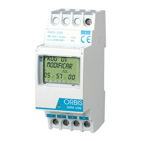
  9. Orbis DATA LOG+ User manual

Orbis DATA LOG+ User manual

DATA LOG + / DATA LOG 2+
DIGITAL TIME SWITCH
INSTRUCTIONS FOR USE
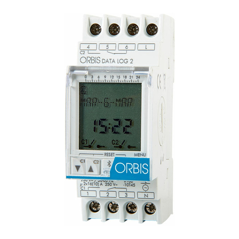
DATA LOG + / DATA LOG 2 + is a digital time switch designed for controlling any
electrical installation. It includes the possibility of carrying out short-duration or
pulsed operations (from 1 to 59 seconds), On and Off at a set time, repetitive
cycles (from 1 minute to 99 hours, 59 minutes), automatic summer/winter time
change, holiday (day/month) period, adjustable screen brightness and updating
from an infrared remote control. All these features can be applied to channel C1,
and to C2 if DATA LOG 2+ is used.
Function menus can appear in several languages and they display a chronogram
on screen that shows the programming for the current day.
To view the chronogram, as well as the other unit configurations, it is only
necessary to repeatedly press the key (info) until the desired display is
obtained.
DATA LOG + has one independent voltage-free switched circuit that allows the
programming of up to 70 operations.
DATA LOG 2+ has 2 independent voltage-free switched circuits that allow the
programming of up to 70 operations between channel 1 and/or channel 2.
INSTALLATION
WARNING: installation and mounting of electric apparatus shall be carried out by
an authorised installer.
ALL POWER MUST BE REMOVED BEFORE PROCEEDING WITH THE INSTALLATION,.
The unit is internally protected from interference by a safety circuit. However,
certain particularly strong fields can alter its operation. Interference can be avoided
if the following installation rules are followed:
- The unit should not be installed next to inductive loads (motors, transformers and
contactors etc.)
- It is recommended to provide a separate line for the supply (if necessary,
equipped with a mains filter).
- Inductive loads must be fitted with interference suppressors (varistor, RC filter).
If the time switch is used in combination with other units at an installation, it is
necessary to check that the assembly so formed does not generate parasitic
interference.
THE POWER SHALL ONLY BE RESTORED WHEN THE EQUIPMENT IS COMPLETELY
INSTALLED.
MOUNTING
Electronic control device for independent installation in distribution cabinet fitted
with symmetrical 35 mm profile in accordance with the standard EN 60715 (DIN
Rail EN 60715 (Rail DIN).
CONNECTION
Connect the mains supply according to the following schematic:
The Line and Neutral position must be respected, checking the connections made.
A wrong connection can destroy the unit.
PUTTING IN SERVICE
For the device to be able to execute control over the installation, IT MUST BE
POWERED UP.
The display will light up and the MAIN screen will appear.
When the equipment is switched off, the screen will also be off, but the date, time
and all programming will be maintained during the four-year lifetime of the
incorporated lithium battery.
In this case, if any key is pressed, the display will temporarily switch on to allow
programming. If no keys are pressed during fifteen seconds, the display will be
switched off again.
These units have an LCD panel and four keys for adjustment and programming.
The following information is shown on the LCD:
•Day of the week in text line 1 in the ON state
•Complete time and date
•Symbol = Vacation state
•Chronogram with the operations for that day
•State of circuits C1 / C2: ON , OFF
•INFO symbol
•PERMANENT text in line 2 (if activated)
•OFF text in line 1 (if in switched-off state)
•LOG technology: two text lines for programming help menus
•Two lines of text in programming help menu style and a chronogram with
48 divisions in which each segment represents thirty minutes
CONFIGURATION
DATA LOG +/ DATA LOG 2+ units leave the factory configured with the current
date and time, and configured as follows:
Hour Mode: 24 h
W-S Change Automatic (last Sunday of March)
S-W Change Automatic (last Sunday of October)
Vacations: NO (deactivated)
Programs: None (memory empty)
PROGRAMMING
The programming is based on menus and submenus through which we can move
to program operations or make adjustments to the unit. Access to the main menu
from the idle screen is by pressing key √. Use the ▼and ▲keys to step through
the different menus, which can be entered by pressing key √. To go back to the
previous menu, press key C.
The data to be entered always appear flashing on the screen.
The structure of the menus is the following:
MAIN MENU
•PROGRAMS. This is the menu where the different operations are programmed.
There are 70 memory slots (from PROG_01 to PROG_70).
oENTER. Where we will edit the different programs. With the ▼and ▲keys,
we can step from PROG_01 to PROG_70. After selecting one, it is entered
by pressing √. Once inside the program, we have the following options:
-EDIT. The message “PROG_01: EDIT” is shown on screen. By
validating with √TYPE C1: ON appears on screen. The type of
operation for the DATA LOG is selected with the ▼and ▲keys: C1:
ON, C1: OFF, C1: PULSE, C1: CYCLE. In the case of DATA LOG 2+,
we also have C2: ON, C2: OFF, C2: PULSE, C2: CYCLE. The choice
made is validated with key √. Next the hour, minute and combination of
days of the week are chosen for the operation.
In the case of PULSES, it will be necessary to specify the pulse
duration in seconds.
In the case of CYCLES, it is necessary to specify when the cycle will
begin (hour, minute and day of the week); and then, when the cycle
finishes (hour, minute and day of the week). To end the CYCLE
definition, it would only remain to indicate the ON period and the OFF
period respectively (in hours and minutes).
-COPY. It copies the operation of a program for use in another.
-PASTE. It pastes the previously copied operation.
-ERASE. It deletes the selected program.
oERASE. It allows a deletion to be carried out of all the operations in the
programs in one step.
•CLOCK. This will set the equipment time. The variables to be configured are (in
this order): year, month, day, hour and minute. The day of the week is
automatically calculated.
•PERMANENT. This is the menu in which we can fix a permanent operation (On
/ Off) of channel C1, and of channel C2 in the case of DATA LOG 2+. With the
▼and ▲keys we step through the different options: C1: YES ÆC1: NO ÆC2:
YES ÆC2: NO. We validate the case we want with √. The equipment will not
follow the operations programming for the selected channel if OPTION YES is
selected.
The contact position can be changed manually.
•LANGUAGE. This is the menu where the unit language is set.
•SETTINGS. This is the menu in which most of the unit configurations can be
carried out.
oSEASON. It establishes the time change mode Summer - Winter and Winter
- Summer.
-AUTO. It automatically carries out the time change on the last Sunday of
March and on the last Sunday of October.
-MANUAL. It allows the day and time to be chosen for carrying out the time
change.
-DESACT. The time change is not carried out.
DAY OF THE WEEK
CHRONOGRAM
INFO SYMBOL
DATE
CURRENT TIME
HOLIDAY
SYMBOL
INFO SYMBOL
CIRCUIT 2
STATUS
STANDBY STATUS DISPLAY C1 (INFO) STATUS DISPLAY
CIRCUIT 1
STATUS
3
2
1
654
N
L
M
~ON
C1 1 - 2
C2 4 - 5
C1
C2
3
2
1 N
L
M
~
C1
DATA LOG + DATA LOG 2+
OPEN
CLOSE
oHOLIDAYS. This is employed to choose a date period (day/month) on which
the unit will be deactivated (switched off). This period will repeated year by
year and begin to count from the 00:00:00 hours of the start day until the
23:59:59 hours of the end day.
-DEACT. No holiday adjustment.
-EDIT. Configure the start day and the end day of the holiday lapse.
oKEYBOARD. Menu to activate or deactivate the keyboard blocking protection
to prevent unwanted access.
-BLOCK: NO. Protection is disabled.
-BLOCK: YES. Protection is enabled.
This protection is automatically activated 10 seconds after entering into
MAIN screen mode. If keyboard is pressed, message KEYBOARD
BLOCKED is displayed. At this point, in order to grant access and clears
the protection, next keyboard sequence must be pressed: C▼▲C√√.
If a wrong sequence is pressed, message KEYBOARD ERROR will be
displayed during several seconds. If correct sequence is pressed,
NORMAL mode will be displayed and the device will be unprotected for 10
seconds. During this lapse, access to MENU functions is granted by
pressing √.
oCOUNTER. Menu in which we will be able to know the ON-time (in hours) of
each channel.
-ERASE C1. It puts the hour counter of channel 1 to zero
-ERASE C2. It puts the hour counter of channel 2 to zero
oINFRARED. For data downloading using the remote control, see the section
DATA DOWNLOADING WITH THE REMOTE CONTROL). This option only
works when the appliance is connected to the power mains.
oCONTRAST. Menu in which we can increase or reduce the display contrast.
-MINIMUM, LOW, MEDIUM, HIGH, MAXIMUM
When a key is pressed, the contrast will rise to the maximum level for three
seconds. If no key has been pressed at the end of this time, the contrast will
return to the previously selected value.
The display is always at maximum contrast during programming.
oVERSION. This indicates the installed software version.
If operations are programmed that coincide in time, it must be taken into account
that some take priority over others. The priority order is as follows:
OFF MODE ÆPERMANENT MODE ÆMANUAL ÆPROG_01 ÆPROG_02 Æ
…. ÆPROG_70
The data to be programmed always appear on screen in flashing mode.
MANUAL OPERATION
The status of the circuits may be temporarily activated or deactivated when in
NORMAL mode by pressing the▼C1 and ▲C2 keys. The symbol will appear
on the screen until a programmed automatic operation takes place.
Once changed, it is possible to return to NORMAL mode by repeatedly pressing C.
To verify channel status, the key (INFO) should be pressed until the desired
information appears.
RESET
Pressing the four keys at the same time until START AT appears on the display will
delete all existing programming and the LANGUAGE MENU operating mode will be
entered. The unit must be switched on in order to execute RESET.
BATTERY CHANGE
The unit has an operational 4-year backup using a replaceable lithium battery.
Replacement of the battery is carried out by withdrawing the rotating button located
on the right side of the unit. When the battery is exhausted and the device is not
powered up “REPLACE BATTERY” is shown on the screen.
NOTE: When changing the battery the unit programming is not lost, however the
current time is lost. So we have to carry out the TIME SETTING again by means of
the CLOCK menu.
The battery cover is opened by rotating it counter-clockwise (marked by an arrow)
with a coin or other flat object inserted into its slot, until the cover index coincides
with the open position on the unit. After replacing the battery, the cover is inserted
by placing it in the same position with the cover index coinciding with the open
position on the unit and then turning it clockwise until the cover index coincides
with the closed position on the unit.
SWITCH THE UNIT OFF WHEN REPLACING THE BATTERY
DATA-DOWNLOADING WITH THE REMOTE CONTROL
Provided the DATA LOG + / 2+ is powered up, it can be controlled using an
infrared remote control. Both the DATA and GPS SAT remote control models can
be used with the DATA LOG + / 2+.
This control can be used to read the equipment configuration, which will consist of
the following parameters:
- Dates and times for summer and winter times changes
- Currently selected backlight intensity
- Language
- Programs
- Keyboard blocking selection
- Holidays (start and end dates)
This control can also be used to download all this configuration or just the current
date and time.
Infrared remote control access can be achieved in three different ways:
1) In normal mode, the DATA LOG + / 2+ detects infrared communication from a
control positioned in front and pressing MENU will cause the text “INFRARED
PRESS MENU” to appear on the screen. Communications with the remote
control can now take place.
2) In normal mode, pressing the MENU key for more than three seconds will
display the text “INFRARED WAITING”. Pressing MENU will provide access to
this function.
3) Pressing MENU in normal mode will enter menu selection. The ▼and ▲keys
are used to select MENU ADJUSTMENTS and MENU is pressed again to enter
this option. The ▼and ▲keys are used to select INFRARED ADJUSTMENTS
and this option is entered by pressing MENU. Entering this menu will display
“INFRARED WAITING” and communications are now available with the remote
control.
TECHNICAL SPECIFICATIONS:
Voltage rating As indicated on the unit
Tolerance ± 10%
Breaking power µ 2x16 (10) A / 250 V~
Maximum recommended loads (N.O):
Incandescent lamps 3000 W
Fluorescent lamps 1200 VA
Low-voltage halogen lamps 2000 VA
Halogen lamps (230 Vac) 3000 W
Low-consumption lamps (CFL) 600 VA
Low-consumption lamps (Downlights) 400 VA
LED lamps 600 VA
Self-consumption Maximum 4.5 VA Inductiv (1.8 W)
Contact AgSnO2switched
Operational accuracy ± 1 s/day at 23 ºC
Variation of accuracy with temp. ± 0.15 s / ºC / 24 h
Running reserve 4 years (without mains supply connection)
Type of action 1S, 1T, 1U
Software class and structure Class A
Memory slots 70
Nº of channels DATA LOG+: 1; DATA LOG 2+: 2
Types of operation FIXED TIME: ON; OFF
Pulse: from 1 to 59 seconds
Cycle: from 1 minute to 99 hours, 59
minutes
Operating precision ± 1 second
Operating temperature -10 ºC to +45 ºC
Transport and storage Temp -20 ºC to +60 ºC
Contamination situation 2
Protection degree IP 20 as per EN60529
Protection class Class II in proper assembly
Transient pulse voltage 2.5 kV
Ball test temperature + 83 ºC for 21.2.5
Keypad accesses cover Lockable
Connection By means of needle post for maximum
cable section of 4 mm²
Battery ½ AA – 3.6 V – 1000 mAh – Li/SOCi2
Casing dimensions 2 DIN modules (35 mm)
DIMENSIONS
WARNING:
This time switch incorporates a battery, the contents of which may be hazardous to
the environment. The unit must not be discarded without taking the precaution to
remove the battery and deposit it in a suitable container for recycling or returning it
to the manufacturer.
02/01.2013 A016.17.56476
ORBIS TECNOLOGÍA ELÉCTRICA S.A.
Lérida, 61 E-28020 MADRID
Tel.: + 34 91 567 22 77 Fax + 34 91 571 40 06
E-mail: [email protected]
http://www.orbis.es
35
88
60
65

This manual suits for next models

1

Other Orbis Timer manuals

Orbis MINI T User manual

Orbis

Orbis MINI T User manual

Orbis DATA ASTRO User manual

Orbis

Orbis DATA ASTRO User manual

Orbis ASTRO UNO User manual

Orbis

Orbis ASTRO UNO User manual

Orbis ASTRO NOVA CITY User manual

Orbis

Orbis ASTRO NOVA CITY User manual

Orbis INCA DUO User manual

Orbis

Orbis INCA DUO User manual

Orbis ASTRO SAT User manual

Orbis

Orbis ASTRO SAT User manual

Orbis MINI T User manual

Orbis

Orbis MINI T User manual

Orbis DATA MICRO 2+ User manual

Orbis

Orbis DATA MICRO 2+ User manual

Orbis Supra User manual

Orbis

Orbis Supra User manual

Orbis ASTRO NOVA CITY User manual

Orbis

Orbis ASTRO NOVA CITY User manual

Orbis ASTRO SAT User manual

Orbis

Orbis ASTRO SAT User manual

Orbis DATA MICRO + User manual

Orbis

Orbis DATA MICRO + User manual

Orbis DATA LOG User manual

Orbis

Orbis DATA LOG User manual

Orbis ASTRO NOVA User manual

Orbis

Orbis ASTRO NOVA User manual

Orbis DATA LOG BT User manual

Orbis

Orbis DATA LOG BT User manual

Orbis TEMPO + User manual

Orbis

Orbis TEMPO + User manual

Orbis DUO User manual

Orbis

Orbis DUO User manual

Orbis TEMPO + User manual

Orbis

Orbis TEMPO + User manual

Orbis DATA MICRO + User manual

Orbis

Orbis DATA MICRO + User manual

Orbis suevia ASTRO NOVA CITY User manual

Orbis

Orbis suevia ASTRO NOVA CITY User manual

Orbis UNO User manual

Orbis

Orbis UNO User manual

Orbis ASTRO LOG User manual

Orbis

Orbis ASTRO LOG User manual

Orbis ASTRO NOVA CITY User manual

Orbis

Orbis ASTRO NOVA CITY User manual

Orbis DATA MULTI ANUAL Guide

Orbis

Orbis DATA MULTI ANUAL Guide

Popular Timer manuals by other brands

Intermatic HB800 Series Installation and user instructions

Intermatic

Intermatic HB800 Series Installation and user instructions

ATC 7DT-2CH Installation & operation manual

ATC

ATC 7DT-2CH Installation & operation manual

brennenstuhl BDZ 44 DE 3655 operating manual

brennenstuhl

brennenstuhl BDZ 44 DE 3655 operating manual

Glen Dimplex Nordic AS timer user manual

Glen Dimplex Nordic AS

Glen Dimplex Nordic AS timer user manual

Innovative TE 501 instructions

Innovative

Innovative TE 501 instructions

Acroprint 200 Service and parts manual

Acroprint

Acroprint 200 Service and parts manual

LEGRAND Lexic MicroRex D22 operating instructions

LEGRAND

LEGRAND Lexic MicroRex D22 operating instructions

Velleman K2579 Assembly manual

Velleman

Velleman K2579 Assembly manual

BDH Elkay 380A-1 Instruction guide

BDH

BDH Elkay 380A-1 Instruction guide

TFA 38.2032 instruction manual

TFA

TFA 38.2032 instruction manual

Diivoo WT-02 user manual

Diivoo

Diivoo WT-02 user manual

GE GE 15136 quick start guide

GE

GE GE 15136 quick start guide

Mitsubishi Electric PAC-YT32PTA installation manual

Mitsubishi Electric

Mitsubishi Electric PAC-YT32PTA installation manual

Robic SC-848W operating instructions

Robic

Robic SC-848W operating instructions

König Electronic HC-WBT10 manual

König Electronic

König Electronic HC-WBT10 manual

Robic SC-606W instructions

Robic

Robic SC-606W instructions

FATT Advance Plus instruction manual

FATT

FATT Advance Plus instruction manual

Intermatic DT7 user guide

Intermatic

Intermatic DT7 user guide

manuals.online logo
manuals.online logoBrands
  • About & Mission
  • Contact us
  • Privacy Policy
  • Terms and Conditions

Copyright 2025 Manuals.Online. All Rights Reserved.