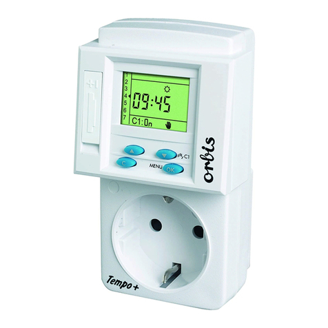
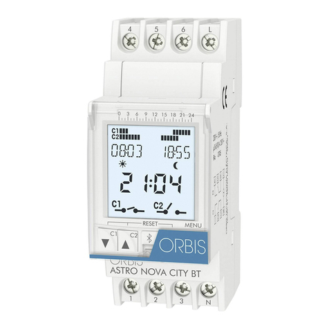
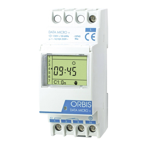
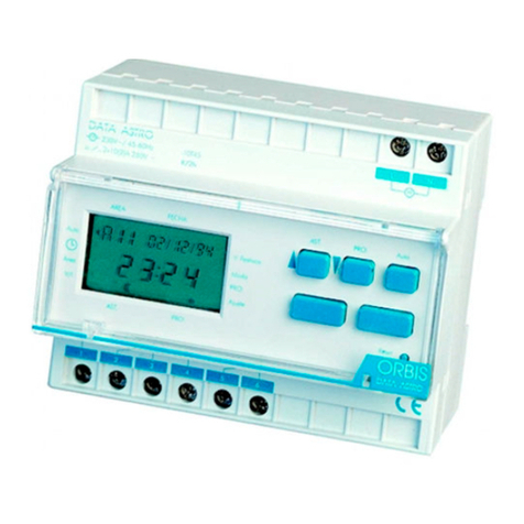
DIGITAL TIME SWITCH
DATA MICRO + / DATA MICRO 2+
OPERATING INSTRUCTIONS
DESCRIPTION
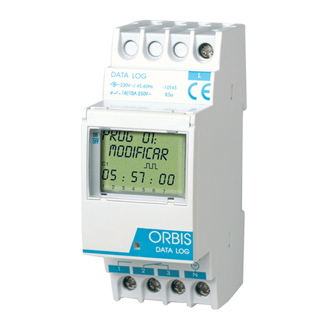
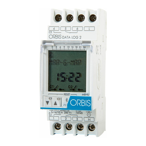
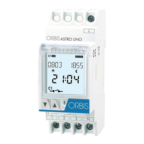
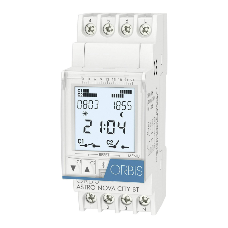
DATA MICRO +is a time switch designed to control any electrical installation.
Includes pulse programming from 1 to 59 seconds and up to 32 block memory
spaces. Automatic winter ! summer official time adjustment.
INSTALLATION
ATTENTION: Electrical devices must be installed and assembled by authorized
installer.
VERY IMPORTANT: This time switch is protected internally against interference by a
safety device. However, particularly strong electromagnetic fields may alter its
operation. Such interference can be avoided by adhering to the following
recommendations during installation:
-The device should not be installed near inductive loads (motors, transformers,
contactors, etc)
-A separate power line is recommended (equipped with a network filter if
necessary)
-Inductive loads should be equipped with interference suppressors (varistor, RC
filter)
If the time switch is to be used in combination with other devices in an installation, it
is necessary to verify that no parasitic disturbances will be caused by the group.
MOUNTING: Electronic control device for independent installation in distribution
cabinet fitted with symmetrical 35 mm profile in accordance with the standard EN
60715 (DIN Rail EN 60715 (Rail DIN).
CONNECTION:
Connect according with the following schema:
STARTING UP AND PROGRAMMING
DATA MICRO +is already programmed with current date and time, and with the
official automatic winter ! summer official time adjustment activated (last Sunday in
March and last Sunday in October).
Programming is based in menus (indicated by icons):
x- Programming.
x- Clock setting.
x- Winter / summer official time change.
x- Holidays period programming.
RESET
Although the clock of the device is already programmed, if a RESET is needed
(blank display, inconsistent data, etc), press at the same time the four keys during 3
seconds. In this moment, the device loses all data and goes to clock setting mode,
directly to program year, month, day, day of the week, hour and minutes.
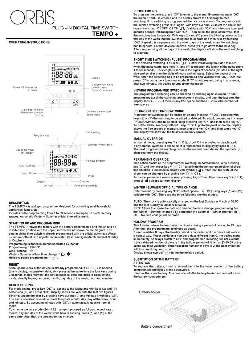
CLOCK SETTING. FIG 1.
For clock setting, press key to access to the Menu and with keys and
select icon and press . Display shows the year with the last two figures
blinking; update the year by pressing keys and and validate it with key
.
The same operation should be made to update month, day, day of the week, hour
and minutes. By accepting minutes with , it automatically goes to normal mode.
To change the time mode (24h/12h am-pm) proceed as follows: accept year, month,
day and day of the week; while hour is blinking, press and at the same
time. After that, the time mode has change.
PROGRAMMING. FIG 2 and 3.
To program the device, press to enter to the menu. By pressing again the
menu is entered and the display shows the first programmed switching. If no
switching is programmed then - - : - - is shown. To program or edit the desired
switching press again, with keys and select the circuit and type of
switching: C1 OFF, C1 ON, C1 ON ,(C2 OFF, C2 ON, C2 ON only in model
DATA MICRO 2+). Validate with and introduce hour and minutes desired,
validating then with . Then select the days of the week that the switching has to
operate. With keys and place the blinking cursor on the first day of the
week that the switching has to operate and then fix it by pressing . Repeat this
sequence with the other days of the week when the switching has to operate. For the
days not desired, press to go down to the next day. After programming all the
days of the week, the display will show the next switching to program.
SHORT TIME SWITCHING (PULSE) PROGRAMMING. FIG 4.
If the selected switching is a Pulse , after introducing hour and minutes when the
pulse starts, use keys and to program the length of the pulse (from 1 to
59 seconds). This length is shown in the digits of seconds (situated at the right side
and smaller than the digits of hours and minutes). Select the day(s) of the week
when the switching has to be programmed and validate with . After that, press
to come back to normal mode. If is not pressed, being in any mode, after
two minutes, the device returns to normal mode.
VIEWING PROGRAMMED SWITCHING. FIG 5.
The programmed switching can be checked by entering again in menu and
pressing key all the switching are shown in display, and after the last one, the
display shows - - : - -, if there is any free space and then it shows the number of free
spaces.
EDITING OR DELETING SWITCHING
Programmed switching can be edited or deleted in menu , selecting with keys
or the switching to be edited or deleted. To edit it, proceed as in clause
PROGRAMMING and to delete it, keep pressing key and then press key .
To delete all the switching without using RESET, go to the point where the display
shows the free spaces of memory, keep pressing key and then press key
. The display will show 32, the total free memory spaces.
MANUAL OVERRIDE. FIG 6.
In normal mode, pressing key ( ), circuit C1 is activated or deactivated.
The same for circuit C2 by using key ( ) (only in DATA MICRO 2+).
If any manual override is executed, it is represented in display by symbol .
The next programmed switching cancels the manual override and the symbol
disappear from the display.
PERMANENT OVERRIDE. FIG 7.
This option blocks all the programmed switching. In normal mode, keep pressing key
and then press key ( ) to activate the permanent position of circuit;
this situation is indicated in display with symbol . After that, the state of the circuit
can be changed by pressing key ( ).
To cancel permanent override keep pressing key and then press key
( ), symbol disappear from display. The same for circuit C2 using key
( ) only in DATA MICRO 2+.
WINTER / SUMMER OFFICIAL TIME CHANGE. FIG 8.
Enter MENU by pressing key ; select option using keys and ,
validate with . There are the three following working modes:
AUTO: The clock is automatically changed on the last Sunday in March al 02:00
and the last Sunday in October at 03:00.
PRO: Allows to choose the date and time for the time change, programming first
the winter ! summer change ( ) and then the summer ! winter change ( ).
OFF: No time change will be made
HOLIDAY PROGRAM. FIG 9.
This function allows deactivating the circuits during a period of time up to 99 days.
After that, the programming continues as usual.
If user validates 0 days, the holiday period is cancelled and the device will work in a
normal way. If user validates a number of days different than 0, the device starts
immediately, so relays switch to OFF and programmed switching will not execute.
If the validated number of days is 1, the holiday period will finish at 23:59:59 of the
same day than validation. If the validation number of days is 2, the holiday period will
finish next day. And so on.
Display shows symbol during the holiday period.
Permanent overrride
Override
Holidays program
Summer / Winter time
Clock setting
On / Off
Day of the week
(1) Monday
AM / PM mode
Hour : Minute
On / Off
Programming
Circuit 1
Pulse
Circuit 2
(only Data Micro 2 +)
1 2 3 N
L
DATA MICRO +
1 2 3 N
L
4 5 6
DATA MICRO 2 +
C2
C
Confirms the selection
Starts menu
C1
OK
MENU
Display
Increment or move up
in menu
Circuit C2 override
(only Data Micro 2 +)
Decrement or move
down in menu
Circuit C1 override
Move back in menu
Permanent override
(C+C1 ó C+C2)

