Orbit OBKB01 User manual

Owner's manual
OBKB01
CAUTION: 1. Weight on this product should not exceed 150kg
2 Exercise of
a
strenuous nature, as is customarily done on this equipment,
Should not be undertaken without first consulting a physician.
No specific health claims are made or implied as they relate to the equipment.
Measurements made by the equipment are believed to be accurate, but only the
measurements of your physician should be relied upon.
IMPORTANT: Read all instruction carefully before using this product. Retain this product owner's
manual for future reference.
•
Warranty
•Assembly
•Parts
OBKB01

L-10
K
L-3
L-6
L-7
E-3
H-1
L-2
M-2
Drawing for Assembly

F-4 F-3
F-2
F-1
F-5
G-11 G-13
Exploded drawing

Parts List
Part No.
Description Spec. QTY
A Computer 1PCS
A-1 Screw 4PCS
B Axle assembly 1SET
B-1 Hex. Bolt 3PCS
B-2 Drive pulley 1PCS
B-3 Sleeve 1PCS
B-4 Axle set 1PCS
C Flywheel assembly 1SET
C-1 Flywheel 1PCS
C-2 Star washer 2PCS
C-3 Nut 3PCS
C-4 Flat washer 1PCS
C-5 Bearing 1PCS
C-6 Bearing 1PCS
C-7 One-way bearing set 1PCS
C-8 Bearing 1PCS
C-9 Bearing 1PCS
C-10 Axle for flywheel 1PCS
C-12 Sleeve for flywheel 1PCS
C-13 Pulley 1PCS
D Idler wheel assembly 1SET
D-1 Idler set 1PCS
D-2 Idler wheel φ24xφ37x20.5mmL
1PCS
D-3 Nut 1PCS
D-4 Flat washer φ8.5xφ25x1t 1PCS
D-5 Hex. Bolt M8xP1.25x20L 1PCS
D-6 Wave washer φ10.5xφ15x0.3t 2PCS
D-7 Flat washer φ6xφ12x1t 1PCS
D-8 Hex. Bolt M6xP1.0x12L 1PCS
E Screws for handlebar post 1SET
E-1 Flat washer φ8xφ19x2t 2PCS
E-2 Allen bolt M8xP1.25x16L 4PCS
E-3 Semi-circular washer φ8xφ19x2t 2PCS
F Magnet set assembly 1SET
F-1 Magnet set 1PCS
F-2 Hex. Bolt M6xP1.0*16L 2PCS
F-3 Spring washer 2PCS
F-4 Flat washer φ6xφ13x1t 2PCS
F-5 Gear box 1PCS
G Main frame assembly 1SET

G-1 Main frame 1PCS
G-2 Resistant screws 2PCS
G-3 Adjustable knob 1PCS
G-4 Screw M4x10L 1PCS
G-5 Wave washer φ17.5xφ25x0.3t 1PCS
G-6 Flat washer φ17.5xφ25x0.3t 1PCS
G-7 C-ring 1PCS
G-8 Crank (Left) 1PCS
G-9 Crank (Right) 1PCS
G-10 Sleeve for seat post 1PCS
G-11 Bearing 2PCS
G-12 Idler spring ODφ16xφ2.0x35T 1PCS
G-13 Sensor box 1PCS
G-14 Sensor holder 1PCS
G-15 DC wire 1PCS
G-16 Belt 1PCS
G-17 Chain cover(left) 1PCS
G-18 Chain cover(right) 1PCS
G-19 Self-tapping screw M4x50L 6PCS
G-20 Self-tapping screw M4x30L 1PCS
G-21 Drilling screws 3/16″(#10)x3/4″
6PCS
G-22 Adapter
230V 50HZ,9VDC
1.5A 1PCS
G-23 Cover for handlebar post 1PCS
G-24 Pedal 1PCS
G-25 Sensor wire (lower) 1PCS
H Handlebar post assembly 1SET
H-1 Handlebar post 1PCS
H-2 Sensor wire (Upper) 1PCS
I Rear stabilizer assembly 1SET
I-1 Drilling screws 4PCS
I-2 End cap (Left) 1PCS
I-3 Adjustable cap 2PCS
I-4 End cap (Right) 1PCS
I-5 Rear stabilizer 50*98*1.5tx400L 1PCS
J Front stabilizer assembly 1SET
J-1 End cap (Left) 1PCS
J-2 Allen bolt M8xP1.25x40L 2PCS
J-3 Transport wheel φ57xφ8x20 2PCS
J-4 Nut 2PCS
J-5 Flat washer φ8*φ19*2T 2PCS
J-6 End cap (Right) 1PCS
J-7 Front stabilizer 1PCS

J-8 Drilling screws 4PCS
K Seat post 1SET
L Seat slider assembly 1SET
L-1 Screw M5xP0.8x12L 2PCS
L-2 Cover for seat slider(R) 1PCS
L-3 Seat slider 1PCS
L-4 Cap for seat slider 1PCS
L-5 Fixing screw bracket 7/16"-14 1PCS
L-6 Flat washer φ14.3xφ25x2.0t 1PCS
L-7 Knob for seat slider 1PCS
L-8 Cover for seat slider (L) 1PCS
L-9 Self-tapping screw M4x15L 1PCS
L-10 Seat 1PCS
M Handlebar assembly 1SET
M-1 Foam grip 550xφ20x5m/m 2PCS
M-2 Handlebar 1PCS
M-3 Hand pulse 2PCS
M-4 Cap for handlebar φ7/8" 2PCS
M-5 Hand pulse wire 1PCS
M-6 Self-tapping screw M4x20L 2PCS
M-7 Cap for wire 1PCS
N Tools 1SET
N-1 Allen bolt M8xP1.25x20L(6m/m)
8PCS
N-2 Flat washer φ8xφ19x2t 8PCS
N-3 Wrench 1PCS
N-4 Allen Key 1PCS
N-5 Box spanner 1PCS
N-6 T-knob for handlebar M8xP1.25x65L 1PCS
N-7 Cover for handlebar post 1PCS

Assembly Stage #1
M8*16L 8*2T
*8
J-7
G-1
I-5
1. Attach the front Stabilizer (J-7) to the main Frame (G-1) using two screws (N-1) and flat
washers (N-2).
2. Attach the rear Stabilizer (I-5) to the main Frame (G-1) using two screws (N-1) and flat
washers (N-2).

Assembly Stage #2
R
L
G-24
G-24
G-1
G-8
1. Assemble the two pedals (G-24 R+L) onto the Crank (G-8, G-9) with a screw driver.
Remarks: Screw the left pedal’s spindle counter-clockwise and the right pedal’s
spindle clockwise. Use a wrench (or screwdriver) to screw the two spindles completely
.

Assembly Stage #3
K
G-1
1. Assemble the seat (L-10) to the seat slider. The Slider can be adjusted in different angles.
Tighten the two Nuts under the Seat using a screwdriver. In addition, the Slider can be
adjusted in horizontal level by loosening the Knob.
2. Insert the seat post (K) into the main frame (G-1), and then choose the desired position,
and tighten the knob (G-3). Be sure the knob is always tightened.
Remarks: When you have chosen a desired position,
and tighten the Seat Post Knob until you hear a “click”.

Assembly Stage #4
M8*16L
H-1
E-3
8*2T
*2
8*2T
*4
1. Put the cover (G-23) into the Handlebar post (H-1).
Connect the sensor wires Upper &
lower (H-2, G-25).
2. Insert the handlebar post (H-1) to the main frame with Allen bolts (E-2),
flat washer (E-1),
and semi-circular washers (E-3) with Allen wrench.

Assembly Stage #5
*
1
M-2
M-5
H-1
1. Assembly the handlebar (M-2) onto the handlebar post (H-1).
2. Put the cover (N-7) and tighten the T-knob (N-6).

Assembly Stage #6
*
4
M-5
Plug the wire (H-2 & M-5) and assemble the computer (A) with 4 screws (A-1) by wrench.

Assembly Stage #7
Plug the adapter (G-22) into socket as picture above.

FGTOOLS & PARTS
Screwdriver (1)
DB01R
N-1 Allen Bolt
M8*P1.25*16L(8)
N-6 T-s ape knob M8*65L(1)
N-2 Regular Was er
φ8*
?
19*2t(8)
Box Spanner(1)
Box Spanner(1)Box Spanner(1)
Box Spanner(1)
Allen Key(1)
Allen Key(1)Allen Key(1)
Allen Key(1)
Screwdriver (1)
DB01R
N-1 Allen Bolt
M8*P1.25*16L(8)
N-6 T-sape knob M8*65L(1)
N-2 Regular Waser
φ8*
?
19*2t(8)
Box Spanner(1)
Box Spanner(1)Box Spanner(1)
Box Spanner(1)
Allen Key(1)
Allen Key(1)Allen Key(1)
Allen Key(1)
1/1
1/1
1/1
1/1
1/1
1/1
1/1

INSTRUCTION MANUAL OF SM2705
BUTTON FUNCTION:
MODE/ENTER
In stop mode, confirm all exercise data setting(Time, DST,CAL, Pulse, etc), and
enter into program.
RESET
Press it in the STOP mode, return to the main menu
. Press the mode 2s at any time, buzzer
sound 1s and LCD display 2s then return to the main menu as “TOTAL RESET”.
START/STOP
To start or stop the system.
RECOVERY
If no pulse input,
no use to press the mode. When pulse is displayed, press it to recovery. It will
Display F1~F6 after 1minute, press it again to check out.
UP
To select training mode and increase the function or value up.
DOWN
To select training mode and decrease function or value down.
POWER ON
When power on, buzzer sound for 1 second. At the same time, LCD full display 2 seconds and then wheel diameter.
After that, enter into normal training mode to select.
ENTER TRAINING MODE
When enter into training mde, MANUAL(MAN) flash 1Hz in the dot matrix. Press UP& DOWN to choose from
MANUAL→PROGRAM→User program→H.R.C→WATT. Press ENTER/MODE to enter the mode. If press
START without selection, directly enter into MANUAL MODE and start.
PROGRAM SETTING
In STOP mode, press P1, P2, P3, ~, P12 to enter relevant program accordingly quickly. Or in the START mode,
Select the program under training mode, press UP&DOWN to choose one from P0, P02, P03, ~, P12.
PROGRAM SETTING LEVEL
Adjust the level in start mode. When using ▲/▼
to adjust, cannot recycle the level(▲can only increase to
Level32, ▼can only decrease to 1).
ADJUSTING MANUAL LEVEL
Adjust the manual level in start mode. Press ▲/▼
to increase or decrease one level. If hold on for
1.5s, will +/- 2levels per second and stop when releasing.
ADJUST THE VALUE (Eg. TIME, DISTANCE, CALORIES, PULSE etc.)
I. Select TIME, DISTANCE, CALORIES, PULSE in Manual mode. Use ▲/▼
t
o adjust the value
Recyclely.
II. When in PROGRAM, User program, H.R.C, WATT mode, only can set the time.
III. Use ▲/▼ to increase or decrease one level; Press ▲/▼ for 1.5s, +/- 8 levels per second and stop
when releasing.
H.R.C
If select H.R.C mode, need set age first and confirm by MODE. It will display preset value in PULSE area
according to age. If select TARGET, it will display 100 and flash in PULSE area. Use ▲/▼to adjust the target
value(30~230) and can be recycle.
User Program
In User PROGRAM mode, user may press ▲/▼to select program drawing
(
each timer shift corresponding
Level value), display and flash in the inserted drawing. It will light after setting. When setting, the figures and
Letters in LOAD Window displaying to be set. LOAD value flash at 1Hz. Press mode to confirm the value after
setting. A complete PROGRAM drawing timer shift has 20 steps need to be set. Then it will run as the set program.
When come to 9
th
step, it scroll and shift to lest and so on. If you want to pause the program halfway, press mode
2s. The unset timer shift will save last time value.
WATT
When entering, the WATT value is flashing to be set(preset value=120). User press ▲/▼to set WATT value. After
Starting, it will adjust automatically according to the WATT value user inserted and exercise status.

SLEEP MODE
No signal(SENSOR, KEYBOARD, PULSE value display) input over 4 minutes, system will enter SLEEP MODE.
All set and calculated value will be saved. When power on and start next time, it will go on with the calculated
value.
FUNCTION
TIME Display range 0:00~99:99 ; Setting range 0:00~99:00
DISTANCE Display range 0.00~99.99 ; Setting range 0~99.90km
CALORIES Display range 0~9999 ; Setting range 0.00~9990
PULSE Display range P-30~230 ; Setting range 0-30~230
WATT Display range 0~999 ; Setting range 10~350
SPEED 0-99.9KM
RPM 0~999
INSPECTION FOR ABNORMAL CONDITION
LCD display E-2: Inspect the electronic watch and console 5PIN connecting cable for peeling off and
poor contact.
LCD no drawing:
1. Check whether the adapter is well inserted into the AC plug seat.
2. Check the adapter DC pin is plugged into the machine or not, whether contact poorly.
3. Check the electronic watch and console 12 PIN connecting cable for peeling off and poor contact.
4. Check DC JACK connecting cable is loose or not.
5. Check the internal 12PIN connecting cable of the electronic watch is loose or not.
Table of contents
Other Orbit Exercise Bike manuals

Orbit
Orbit OBR8301FC User manual

Orbit
Orbit OSP0408 User manual

Orbit
Orbit OBR170M User manual

Orbit
Orbit OBE8731T User manual

Orbit
Orbit OBK 794 User manual

Orbit
Orbit OBR8523FC User manual

Orbit
Orbit OSP209M Kinetic Hybrid Spin Bike User manual

Orbit
Orbit OBK8301FC User manual

Orbit
Orbit OEB3001 User manual

Orbit
Orbit OBK8727 User manual

Orbit
Orbit OBR103 User manual

Orbit
Orbit OSP0270 User manual

Orbit
Orbit OBK170M User manual

Orbit
Orbit OBR8718 User manual
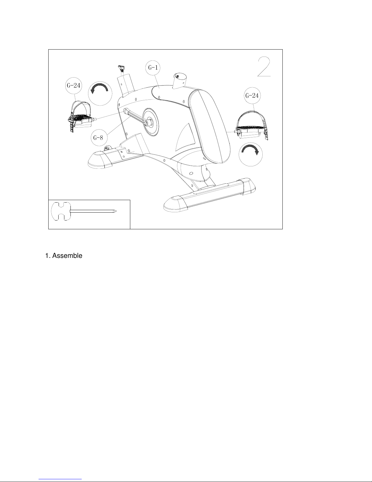
Orbit
Orbit OBK 8604 User manual

Orbit
Orbit OBE8718 User manual

Orbit
Orbit OSP0043 User manual

Orbit
Orbit OBK8612 User manual

Orbit
Orbit OBE8729 User manual

Orbit
Orbit UM3296D User manual