01 Assembly
PRECAUTIONS
WARNING: This bicycle has been designed and constructed to provide maximum safety. Nevertheless, certain
precautions should be taken when using exercise equipment. Read the whole manual before assembling and using
the bicycle. The following safety precautions should also be observed:
1. Before using the exercise bike, please read all instructions in this manual.
2. It is the responsibility of the owner to ensure that all users of the bike are adequately informed
of all precautions. Use the exercise bike only as described in this manual.
3. Use the bike indoors on a level surface and keep it away from moisture and dust. Place a mat
under the stabilizers to protect the carpet or floor.
4. Inspect and tighten all parts regularly. Replace and worm parts immediately
5. Keep children away from this equipment at all times. DO NOT leave them unsupervised in the room where this
bicycle is kept.
6. Wear appropriate exercise clothing when using the bike. Do not wear loose clothing that could
become caught in the bike.
7. If you feel pain or dizziness while exercising, stop immediately and cool down.
8. The pulse sensor is not a medical device. Various factors including the user’s movement, may
affect the accuracy of the heart rate readings. The Pulse sensor is intended only as an exercise
aid in determining heart rate rends in general.
Pre-assembly notes
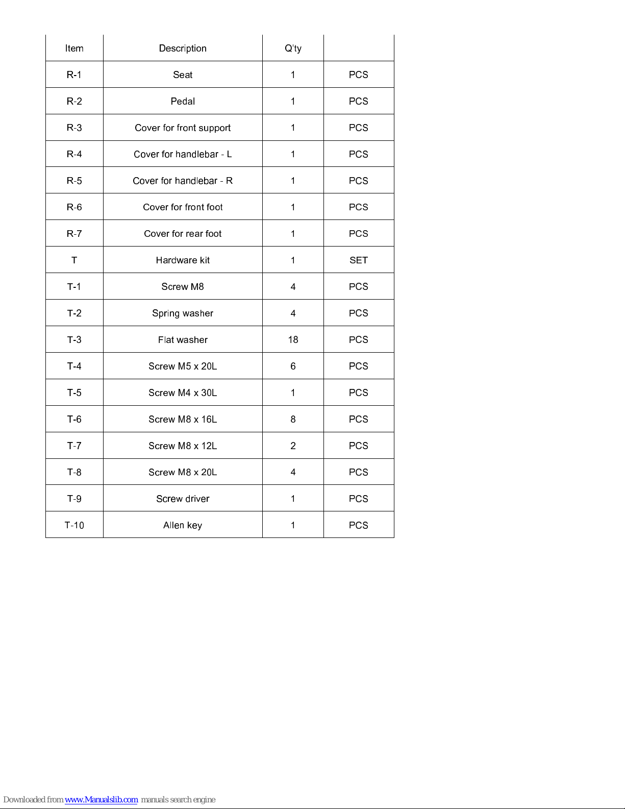
OPEN THE BOXES
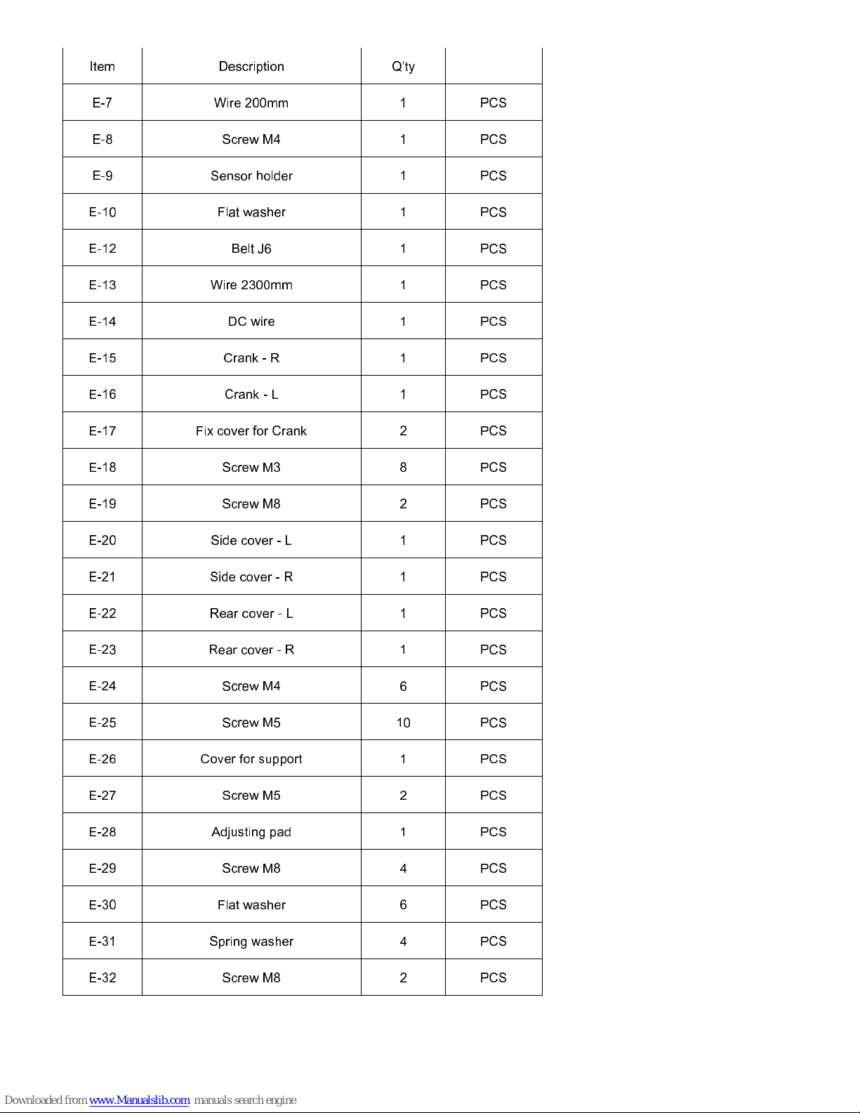
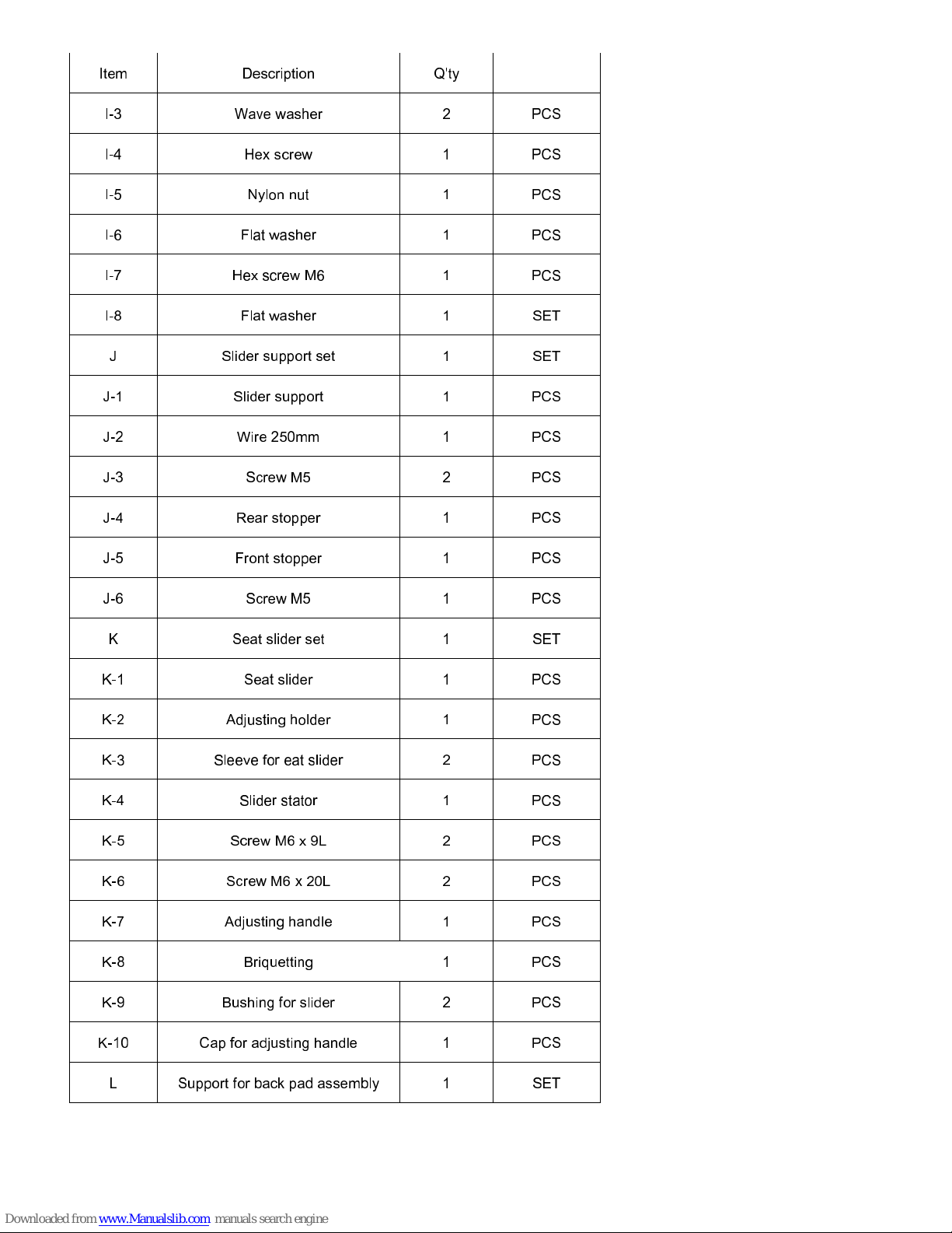
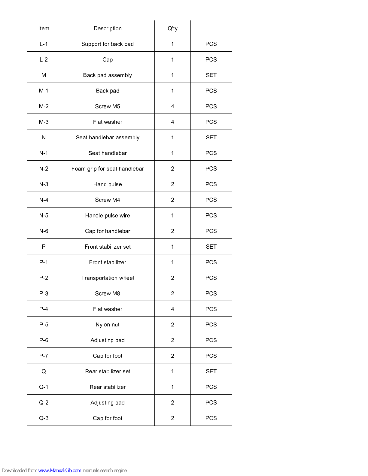
Make sure to inventory all the parts that are included in the boxes. Check The Hardware Chart
for a full count of the number of parts included for proper assembly.
GATHER YOUR TOOLS
Before starting the assembly of your unit, gather the necessary tools. Having all of the equipment at hand
will save time and make the assembly quick and hassle-free.
CLEAR YOUR WORK AREA
Make sure that you have cleared away a large enough space to properly
assemble the unit. Make sure the space is free from anything that may cause
injury during assembly. After the unit is fully assembled, make sure there is a
comfortable amount of free area around the unit for unobstructed operation.


 Service manual")