Oregon 410-120 User guide

410-120
1
ORIGINAL INSTRUCTION MANUAL
Bench Chain Grinder Model 410-120
MANUEL D’INSTRUCTIONS ORIGINAL
Meuleuse électrique pour chaînes de scie
à moteur modèle 410-120
MANUAL ORIGINAL DE INSTRUCCIONES
Afiladora eléctrica para cadenas
de motosierra modelo 410-120

410-120 410-120
2 32
ENGLISH . . . . . . . . . . . . . . . . . . . . . . . . . . . . . . . . . . . . . . . . . . 4
WARNING: READ AND UNDERSTAND ALL SAFETY WARNINGS AND ALL INSTRUCTIONS. FAILURE TO FOLLOW THE
WARNINGS AND INSTRUCTIONS MAY RESULT IN ELECTRIC SHOCK, FIRE AND/OR SERIOUS INJURY.
SAVE ALL WARNINGS AND INSTRUCTIONS FOR FUTURE REFERENCE.
This instruction manual contains translations of a manual drafted in English and are provided to assist those
who do not speak English as their first language. Being a technical writing, some terms may not have a like or
equivalent meaning as translated.Therefore, you should not rely on this translation, and should cross-reference
the English version, where relying on the translated instructions could result in harm to your person or property.
FRANÇAIS . . . . . . . . . . . . . . . . . . . . . . . . . . . . . . . . . . . . . . . . 37
AVERTISSEMENT: VEUILLEZ LIRE ET COMPRENDRE TOUS LES AVERTISSEMENTS DE SÉCURITÉ ET
TOUTES LES INSTRUCTIONS. LE NON-RESPECT DES AVERTISSEMENTS DE SÉCURITÉ ET DES INSTRUCTIONS
PEUT ENTRAÎNER UNE DÉCHARGE ÉLECTRIQUE, UN INCENDIE ET/OU DES BLESSURES GRAVES.
CONSERVEZ L’ENSEMBLE DES AVERTISSEMENTS ET INSTRUCTIONS POUR RÉFÉRENCE ULTÉRIEURE.
Ce manuel d’instructions est une traduction d’un manuel rédigé en anglais, fournie pour aider ceux dont l’anglais
n’est pas la langue maternelle. Étant donné qu’il s’agit d’un document technique, certains termes peuvent ne pas
avoir de signification similaire ou équivalente lorsqu’ils sont traduits. Par conséquent, vous ne devez pas vous fier à
cette traduction et devriez consulter la version anglaise également, au cas où les instructions traduites pourraient
provoquer des blessures ou des dommages matériels.
ESPAÑOL. . . . . . . . . . . . . . . . . . . . . . . . . . . . . . . . . . . . . . . . . 71
ADVERTENCIA: LEA Y COMPRENDATODAS LAS ADVERTENCIAS DE SEGURIDAD Y LAS INSTRUCCIONES.
LA OMISIÓN EN SEGUIR ESTAS ADVERTENCIAS E INSTRUCCIONES PODRÍA OCASIONAR UNA DESCARGA
ELÉCTRICA, UN INCENDIO Y/O LESIONES PERSONALES GRAVES.
GUARDE TODAS LAS ADVERTENCIAS E INSTRUCCIONES PARA REFERENCIA FUTURA.
Este manual de instrucciones contiene traducciones de un manual redactado en inglés y se provee para ayudar a
aquellas personas que no hablan inglés como su primer idioma. Dado que el manual es un documento técnico, es
posible que algunos términos no tengan un significado similar o equivalente al traducirlos. Por lo tanto, no debe
confiar en esta traducción y debe consultar la versión en inglés; confiar en las instrucciones traducidas podría
provocar lesiones personales o daños materiales.

410-120 410-120
4 5
© Blount, Inc. Pricing and specifications subject to change without notice. All rights reserved.
OREGON® is a registered trademark of Blount, Inc. in the United States and/or in other countries.
NAMES AND TERMS
Skilled Technician: a person who is generally employed by the service center and who is trained to carry
out extraordinary maintenance jobs and repairs on the machine.
SYMBOLS AND LABELS
These symbols and labels appear on the tool and/or in this manual.
SYMBOL NAME EXPLANATION
SAFETY ALERT
SYMBOL
INDICATES THAT THE TEXT THAT FOLLOWS EXPLAINS A
DANGER, WARNING, OR CAUTION.
READ INSTRUCTIONS
THE ORIGINAL INSTRUCTION MANUAL CONTAINS IMPORTANT
SAFETY AND OPERATING INFORMATION. READ AND FOLLOW
THE INSTRUCTIONS CAREFULLY.
WEAR EYE
PROTECTION WEAR EYE PROTECTION.
WEAR HAND
PROTECTION WEAR GLOVES WHEN HANDLING SAW CHAIN.
DO NOT DISPOSE DO NOT THROW IN HOUSEHOLD WASTE. TAKETO AN
AUTHORIZED RECYCLER.
DAMAGED CABLE
INSPECT THE POWER CORD REGULARLY FOR DAMAGE.
REMOVE THE PLUG FROM THE MAINS IMMEDIATELY IF THE
CABLE IS DAMAGED OR CUT.
UNPLUG BEFORE
MAINTENANCE UNPLUG BEFORE PERFORMING ANY MAINTENANCE.
Table of Contents
NAMES AND TERMS...................................................................... 5
SYMBOLS AND LABELS................................................................... 5
SAFETY INFORMATION................................................................... 6
SAFETY RULES AND PRECAUTIONS ............................................................6
SETTING UP THE GRINDER.....................................................................8
ELECTRICAL CONNECTION ....................................................................8
GROUNDING INSTRUCTIONS ..................................................................8
GENERAL INFORMATION ......................................................................9
USING AND KEEPING THE OPERATOR’S MANUAL ...............................................9
SAFETY DEVICES ..............................................................................9
INTENDED USE................................................................................9
TECHNICAL DATA .............................................................................9
PART DESCRIPTION .....................................................................10
GRINDING ANGLES CHART ..............................................................12
INSTRUMENTAL MEASUREMENTS........................................................12
PREPARING FOR USE....................................................................13
MOUNTING THE BASE UNIT - MOTOR UNIT ................................................... 13
ASSEMBLY .................................................................................. 14
CHOOSING AND INSTALLING THE GRINDING WHEEL ......................................... 14
SETTING THE SHARPENING ANGLES .....................................................17
FOR RIGHT-HAND CUTTERS WITHOUT A DOWN ANGLE (0°)................................... 18
FOR RIGHT-HAND CUTTERS WITH A DOWN ANGLE ........................................... 19
FOR LEFT-HAND CUTTERS WITHOUT A DOWN ANGLE (0°) .................................... 21
FOR LEFT-HAND CUTTERS WITH A DOWN ANGLE ............................................ 22
PLACING THE CHAIN IN THE VISE.........................................................24
OPERATING INSTRUCTIONS .............................................................26
SHARPENING THE CHAIN .................................................................... 26
GRINDING WHEEL DRESSING FOR SETTING THE DEPTH GAUGE ............................... 28
SETTING THE DEPTH GAUGE. . . . . . . . . . . . . . . . . . . . . . . . . . . . . . . . . . . . . . . . . . . . . . . . . . . . . . . . . . . . . . . . . 29
STOPPING AND SHUTTING DOWN .......................................................30
MAINTENANCE AND CLEANING..........................................................30
DEMOLITION AND DISPOSAL ............................................................30
WARRANTY AND SERVICE ...............................................................31
TROUBLESHOOTING ....................................................................32
ILLUSTRATED PARTS LIST ...............................................................34
TABLE OF CONTENTS NAMES AND SYMBOLS

410-120 410-120
6 7
SAFETY INFORMATION
FOR YOUR OWN SAFETY READ THIS OPERATOR’S
MANUAL BEFORE OPERATING GRINDER
Keep this manual for future reference. To
ensure the correct use of the grinder and to
prevent accidents, do not start working without
having read this manual carefully. The manual
explains how the various components work
and provides instructions for carrying out the
necessary checks and maintenance operations.
SAFETY RULES AND PRECAUTIONS
WARNING The use of accessories or
attachments not recommended by the
manufacturer may result in a risk of injury to
operator or bystander. Any maintenance operation
not described in this manual must only be
carried out by an AUTHORIZED service center.
CAUTION The following instructions
should be carefully followed in order to
reduce the risk of kickback resulting from
improperly sharpened saw chain.
WARNING Replace cracked or
damaged grinding wheel immediately.
Serious injury to operator or bystander
could result from a damaged wheel.
USERS
The grinder must only be used by adults.
Users must be in good physical condition
and familiar with the instructions for use.
KEEP BYSTANDERS AND CHILDREN AWAY
All bystanders should be kept at a
safe distance from work area.
WEAR PROPER APPAREL
Never wear loose clothing, bracelets, neckties, rings
or any other jewelry that could come into contact
or get caught with the grinding wheel or any other
moving parts. Nonslip footwear is recommended.
Wear protective hair covering to contain long hair.
ALWAYS USE SAFETY GLASSES
AND GLOVES
Always wear gloves and protective eyewear
while operating the grinder and while retouching
the grinding wheel using the dressing stone.
Also use face or dust mask if cutting operation
is dusty. Everyday eyeglasses only have impact
resistant lenses, they are NOT safety glasses.
NEVER STOP THE WHEEL WITH YOUR HANDS
Never attempt to stop the rotation of the
grinding wheel with your hands.
DISCONNECT TOOLS BEFORE SERVICING
Make sure the plug is disconnected when tting
or changing the grinding wheel and during any
other operation of maintenance or transport.
KEEP GUARDS IN PLACE AND
IN WORKING ORDER
Never start the grinder without
the wheel guards in place.
REMOVE ADJUSTING KEYS ANDWRENCHES
Make sure that keys and adjusting wrenches
are removed from tool before turning it on.
DON’T FORCE TOOL
It will do the job better and safer at the
rate for which it was designed. Each
grinder has a plate indicating:
–Size of arbor: Ø .866" (22 mm)
–No-load speed in revolutions
per minute: RPM 3150
–Always read operator’s manual
before operating the machine
–Always wear eye and face protection
–Always use the proper grinding wheel
Also make sure that the voltage and frequency
indicated on the plate applied to the grinder
correspond to those of the mains hook-up.
REDUCE THE RISK OF
UNINTENTIONAL STARTING
Always make sure that the start-up
switch is in the“0” (OFF) position before
connecting the plug to the outlet.
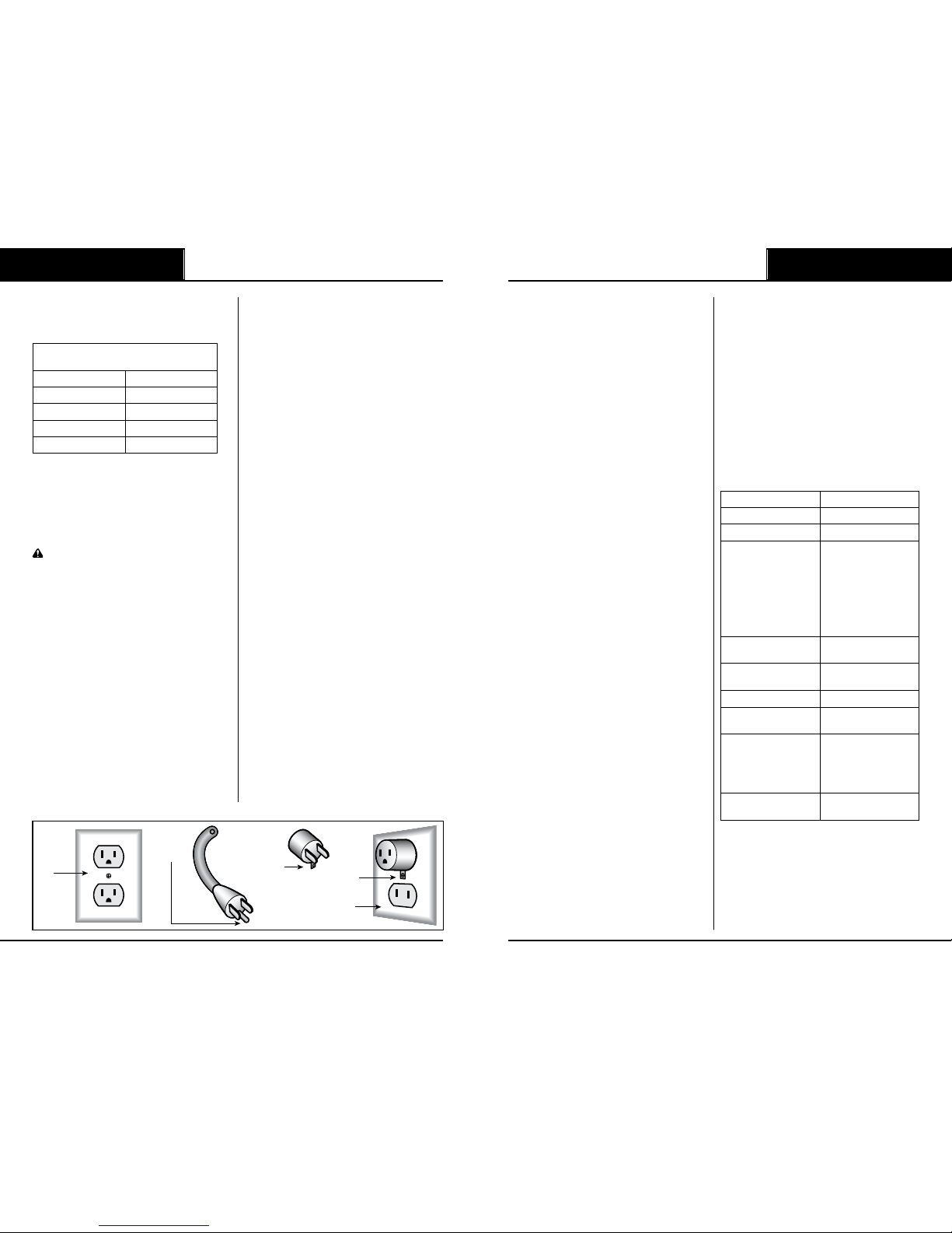
NEVER USE CABLES, PLUGS OR
EXTENSION CABLES THAT ARE
DEFECTIVE OR NON-STANDARD
See “Minimum Extension Cord Gauges”table
on page 12 Remove the plug from the mains
immediately if the cable is damaged or cut;
for cable repair or replacement, contact your
authorized dealer or service center. The power
supply cable is complete with terminals – with
protection. The internal electrical connection
consists of inserting the feeding cable terminals
directly in the switch. The electrical connection
to the mains shall be made in such a way as
to prevent damage by people or vehicles
which could endanger both them and you.
KEEP WORK AREA CLEAN
Cluttered areas and benches invite accidents.
Make sure that the grinding wheel working
area is free of tools or other objects before
starting up the grinder. Frequently clean
grinding dust from beneath grinder.
DON’T USE IN DANGEROUS ENVIRONMENTS
Don’t use power tools in damp or wet locations, or
expose them to rain. Keep work area well-lighted.
CHECK THE POSITION OF THE
CABLE DURING OPERATION
Make sure that the cable remains outside
the range of action of the grinding wheel
and is not under tension. Never operate in
the vicinity of other electrical cables.
DIRECTION OF FEED
Feed work into a blade or cutter against
the direction of rotation of the blade or
cutter only. Never advance the chain with
your left hand until the grinding wheel has
moved entirely outside the work area.
MAKE WORKSHOP CHILD PROOF
Use padlocks, master switches. Do not
allow anyone but the user to remain in the
vicinity of the grinder while it is operating
or to touch the grinder supply cable.
ALWAYS KEEP THE HAND GRIPS
CLEAN AND DRY
SECURE GRINDING WHEEL
Make sure the grinding wheel is secured
before starting the grinder. Do not
over-tighten the wheel nut.
SECURE WORK
Make sure that the machine is stable
and rmly secured. Use the vise to hold
chain. This frees both hands for moving
the wheel down to grind the chain.
DON’T OVERREACH
Keep proper footing and balance at all times.
NEVER STAND ON TOOL
Always work in a stable and safe position. Serious
injury could occur if the tool is tipped or if the
cutting tool is unintentionally contacted.
ALWAYS FOLLOW MAINTENANCE
INSTRUCTIONS
CHECK FOR DAMAGED PARTS
Before using the grinder, check to make sure
that all the devices, those for safety and others,
are in good working order. A guard, a wheel or
other part that is damaged should be carefully
checked to determine that it will operate properly
and perform its intended function – check for
alignment of moving parts, binding of moving
parts, breakage of parts, mounting, and any other
conditions that may aect its operation. A guard,
a wheel or other part that is damaged should
be properly repaired or immediately replaced.
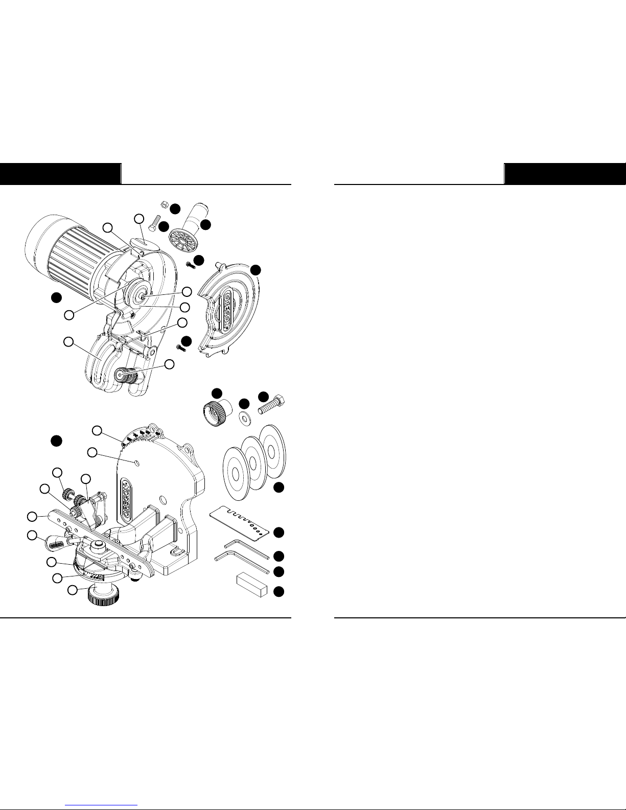
USE RECOMMENDED ACCESSORIES
Consult the operator’s manual for recommended
accessories. The use of improper accessories may
cause risk of injury to persons. Use only anges
furnished with the grinder. To guarantee the
ecient and consistent operation of your grinder,
remember that any worn or broken parts must
only be replaced using ORIGINAL SPARE PARTS.
USE ONLY RECOMMENDED GRINDING WHEELS
CHECK YOUR MACHINE
Never work with a damaged, poorly repaired,
incorrectly tted, or arbitrarily modied grinder. Do
not remove, damage, or disable any safety device.
USE THE RIGHT TOOL
Never use the grinder as a cutter or for
grinding objects other than saw chains.
Don’t force tool or attachment to do a
job for which it was not designed.
EXPERT USERS ONLY
Only lend your grinder to expert users who
are familiar with its operation and correct
use, and always give them the operator’s
manual to read before they start a job.
MAINTAIN TOOLS WITH CARE
Keep tools sharp and clean for best and
safest performance. Follow instructions for
lubricating and changing accessories.
STORE YOUR GRINDER IN A DRY PLACE
Keep it o the ground and out
of the reach of children.
NEVER LET YOUR GRINDER BE
EXPOSED TO RAIN OR DAMPNESS
NEVER USE THE GRINDER IN AN EXPLOSIVE
OR INFLAMMABLE ATMOSPHERE
TAKE THE GRINDER TO YOUR DEALER
When your grinder is not in working order, do not
abandon it on the work site or elsewhere. Take it to
your dealer who will store or dispose of it correctly.
CONSULT YOUR DEALER
Always consult your dealer for any clarication
or important maintenance or repair operation.
NEVER JERK THE CABLE TO DISCONNECT
IT FROM THE OUTLET
Keep the cable away from heat,
oil, and sharp objects.
USE PROPER EXTENSION CORD
Make sure your extension cord is in good
condition. When using an extension cord, be
sure to use one heavy enough to carry the
current your product will draw. An undersized
cord will cause a drop in line voltage resulting
in loss of power and overheating.
SAFETY INFORMATION SAFETY INFORMATION

410-120 410-120
8 9
The table below shows the correct size to use
depending on cord length and nameplate ampere
rating. If in doubt, use the next heavier gauge. The
smaller the gauge number, the heavier the cord.
Minimum Extension Cord
Gauges for 410-120 Grinder
Length Gauge, AWG
25 ft. / 7.6 m 18
50 ft. / 15.2 m 16
100 ft. / 30.5 m 16
150 ft. / 45.7 m 14
NEVER LEAVE TOOL RUNNING UNATTENDED
Turn power o. Do not leave tool until
it comes to a complete stop.
SETTING UP THE GRINDER
CAUTION The grinder must only be used in a
place that is protected from dust and dampness,
is well-lit, out of the reach of children, and away
from gases or other ammable or explosive liquids.
The grinder must be situated near a
normal grounded electrical outlet. Avoid
using dangerous extension cables.
ELECTRICAL CONNECTION
–Make sure the electrical system power
supply complies with the values
written on the rating nameplate.
–The power supply voltage must not dier
from that written on the nameplate by ±5%.
–The connection to the electric mains must be
prepared subject to current standards in force
in the country in which the machine is used.
–The mains used for the machine must be
grounded, have an adequate fuse, and must be
protected by a ground fault protection device
with tripping sensitivity no higher than 30 mA.
GROUNDING INSTRUCTIONS
A. In the event of malfunction or breakdown,
grounding provides a path of least resistance
for electric current to reduce the risk of electric
shock. This tool is equipped with an electric cord
having an equipment-grounding conductor and
a grounding plug. The plug must be plugged
into a matching outlet that is properly installed
and grounded in accordance with all local
codes and ordinances. Do not modify the plug
provided – if it will not t the outlet, have the
proper outlet installed by a qualied electrician.
Improper connection of the equipment-grounding
conductor can result in a risk of electric shock.
The conductor with insulation having an outer
surface that is green with or without yellow
stripes is the equipment-grounding conductor.
If repair or replacement of the electric cord or
plug is necessary, do not connect the equipment-
grounding conductor to a live terminal.
Check with a qualied electrician or service
personnel if the grounding instructions are
not completely understood or if in doubt as
to whether the tool is properly grounded.
Use only 3-wire extension cords that have
3-prong grounding plugs and 3-pole receptacles
that accept the tool’s plug. Repair or replace
damaged or worn cord immediately.
B. Grounded, cord-connected tools intended for
use on a supply circuit having a nominal rating
less than 150V~. This tool is intended for use on
circuit that has an outlet that looks like the one
illustrated in FIG. A. The tool has a grounding
plug that looks like the plug illustrated in FIG. B. A
temporary adapter, which looks like the adapter
illustrated in FIG. C, may be used to connect this
plug to a 2-pole receptacle as shown if a properly
grounded outlet is not available.The temporary
adapter should be used only until a qualied
electrician can install a properly grounded outlet.
The Grounding Means green-colored rigid ear,
lug, and the like, extending from the adapter
must be connected to a permanent ground
such as a properly grounded outlet box.
GENERAL INFORMATION
The manufacturer is not liable for
damages in the following cases:
–Failed observance of the
instructions given herein;
–Use of the machine other than that
described in the“INTENDED USE” section;
–Failure to use in compliance with current
standards on Health & Safety at the workplace;
–Incorrect installation;
–Lack of scheduled maintenance;
–Modications or jobs that are not
authorized by the manufacturer;
–Use of non–original or inadequate spare parts;
–Repairs that are not carried out by a specialist.
USING AND KEEPING THE
OPERATOR’S MANUAL
The characteristics and the information
given in this manual are merely indicative.
The manufacturer reserves the right to add
any modications to the grinder considered
necessary at any time. It is forbidden to
reproduce any part of this document without
authorization on behalf of the manufacturer.
The operator’s manual is an integral part of the
machine and must be kept in a safe place so that
it can be consulted whenever need be. If you
should lose your manual or it should deteriorate,
you can request your dealer or an authorized
service center for another copy. The manual
shall accompany the machine at all times.
SAFETY DEVICES
The grinder is equipped with the safety
devices illustrated on page 10.
– Shield guards: they protect the operator
from parts of the grinding wheel that may
come away during the sharpening process.
These guards must always be tted in place
when the machine is in use. Always make sure
the guards are ecient and tted properly.
Operator safety could be compromised if
the guards are damaged and/or cracked.
– Switch: the machine features a safety switch with
release coil. In the case of a sudden power failure,
the switch trips automatically and disconnects
the machine from the mains. The machine will
not start even if the power supply is suddenly
restored.You need to restart the grinder by
turning the on-o switch to the on position,“l”.
INTENDED USE
This machine is an electrical grinder for
saw chains used on chain saws.
–Use the machine exclusively for the types of
chains stated in the technical data chart.
–Do not use the machine to cut or grind
anything other than the chains envisaged.
–Secure the machine rmly to the bench or wall.
–The machine must not be used in
corrosive or explosive environments.
–Any other use is to be considered improper. The
manufacturer is not liable for damages following
improper or incorrect use of the machine.
TECHNICAL DATA
Model 410-120
Voltage 120V~ 60Hz
Rated power 220W
Grinding wheel
dimensions
Outside Ø :
5 3/4" (145 mm)
Inside Ø:
7/8" (22,2 mm)
Thickness:
1/8"(3.2 mm)
3/16"(4.7 mm)
1/4"(6.3 mm)
Maximum speed of
grinding wheel
3150 min-1
Maximum power
of lamp
0,5W
Acoustic pressure level 77 dB(A)
Level of vibrations on
operating handle
< 2,5 m/s2
Types of chains that
can be sharpened
1/4”
.325"
3/8"
.404"
3/4” (*)
Weight
(complete machine)
13.9 lbs/ 6.3 kg
(*) only with specic kit (vise+grinding
wheel) to be ordered separately.
FIG. A
Cover of
grounded
outlet box
Cover of grounded
outlet box
Adapter
Grounding
Means Metal
Screw
FIG. B
Grounding
Pin
FIG. C
SAFETY INFORMATION SAFETY INFORMATION

410-120 410-120
10 11
A
17
15
14
13
C
D
E
F
F
G
1
2
3
4
11
5
7
12
6
6
8
9
10
L
O
N
M
H
J
I
K
16
B
PART DESCRIPTION
The grinder is supplied already partially assembled.
A. Upper housing / motor unit
B. Base unit
C. Operating handle securing bolt
D. Operating handle securing nut
E. Operating handle
F. Guard securing screws (2)
G. Shield guard
H. Upper housing locking knob (for bench-mount only)
I. Upper housing securing bolt
J. Upper housing washer
K. Grinding wheels:
5 3/4" x 1/8"x 7/8" (145 x 3.2 x 22.2 mm)
5 3/4" x 3/16" x 7/8" (145 x 4.7 x 22.2 mm)
5 3/4" x 1/4" x 7/8" (145 x 6,3 x 22.2 mm)
L. Sharpening template
M. 4 mm Allen wrench
N. 5 mm Allen wrench
O. Dressing brick
1. Operating handle mounting slot
2. Grinding wheel hub
3. Grinding wheel ange screw
4. Grinding wheel ange
5. Height adjustment knob
6. Shield guard mounting holes
7. Upper housing / motor unit mounting slot
8. Saw chain cutter adjustment knob
9. Chain stop adjustment knob
10. Chain stop
11. Head tilt angle guide plate
12. Upper housing / motor unit mounting hole
13. Vise handle
14. Vise (chain jaws)
15. Vise rotate angle guide plate
16. Vise adjustment knob
17. Vise reference mark pointers
PART DESCRIPTION PART DESCRIPTION

410-120
13
410-120
12
PREPARING FOR USE
ATTENTION Do not install the machine at eye level.You are recommended to install it at a height of no
more than 3.9 to 4.2 feet (1.2 – 1.3 m) from the oor. The machine can be bench mounted or wall mounted.
MOUNTING THE BASE UNIT - MOTOR UNIT
SECURING THE UPPER HOUSING / MOTOR UNIT
Insert the bolt (I) in the dedicated slot (7) in the motor unit (A) and through the mounting hole(12)
in the support unit (B). Insert the washer (J) at the front and tighten the locking knob (H).
NOTE: you may need to depress the upper housing to ensure correct alignment.
A
I
7
12
B
J
H
BENCH-MOUNTING
Use two (2) appropriate bolts complete
with washers and nuts (not supplied),
inserted in the securing holes. Make sure
you position the base unit hanging over the
edge of the bench as shown in the detail.
WALL-MOUNTING
NOTE: assemble the upper housing / motor unit (A)
to the base unit (B) before mounting to your wall.
Use four (4) appropriate bolts
complete with washers (not supplied),
inserted in the securing holes.
B
B
GRINDING ANGLES CHART
|X|
Wheel Width
A
Vise Rotate Angle B
Down Angle C
Head Tilt Angle D
Depth Gauge
XA B C D
MICRO
CHISEL®
20-21-22BPX 3/16" 30° 10° 55° .025" .65 mm
25AP, 25A, 25F 1/8" 30° 0° 55° .025" .65 mm
27A, 27AX 3/16" 30° 10° 55° .030" .75 mm
95VPX 3/16" 30° 10° 55° .025" .65 mm
ROUND
GROUND
CHISEL
20-21-22LPX
M20-21-22LPX 3/16" 25° 10° 55° .025" .65 mm
58, 59L, J 3/16" 25° 10° 55° .025" .65 mm
68JX, LX 3/16" 25° 10° 55° .030" .75 mm
68CJ, CL 45° 45° - .030” .75 mm
72-73-75JGX,
JPX, LGX, LPX,
M72-73-75LPX
3/16" 25° 10° 55° .025" .65 mm
72-73-75V 3/16" 25° 10° 55° .025" .65 mm
SEMI
CHISEL
72APX/72-73-75DPX 3/16" 35° 10° 55° .025" .65 mm
91PXL, 91VXL,
M91VLX 1/8" 30° 0° 55° .025" .65 mm
RIPPING
CHAIN
27R, RA 3/16" 10° 10° 50° .030" .75 mm
72-73-75RD 3/16" 10° 10° 50° .025" .65 mm
CHAMFER
CHISEL™
90PX, 90S, 90SG 1/8" 30° 0° 55° .025" .65 mm
91P, 91PX, 91VG,
91VX, M91VX 1/8" 30° 0° 55° .025" .65 mm
INSTRUMENTAL MEASUREMENTS
A Measure the gauge
depth using the
suitable shape.
B Measure the
cutter length.
C Measure the
chain pitch.
A
B
C
A
B
C
GRINDING ANGLES CHART
INSTRUMENTAL MEASUREMENTS PREPARING FOR USE

410-120 410-120
14 15
REMOVE FLANGE
Using the 5 mm Allen wrench (N), remove
the grinding wheel ange screw (3) and the
grinding wheel ange (4) from the hub.
INSTALL GRINDING WHEEL
Insert and perfectly center the grinding wheel
(K) in the dedicated seat on the hub (2).
REINSTALL FLANGE
Using the 5 mm Allen wrench (N), insert
the ange (4) and tighten the screw (3).
Make sure you t the ange as illustrated. If the
grinding wheel is tted with the ange too tight,
it could break during use and put the operator at
risk. To avoid such risk, tighten screw (3) to 62 in-
lbs. (7 Nm). If possible, check with a torque wrench.
REINSTALL WHEEL GUARD
Reinstall wheel guard (G) with guard
securing screw (F) in holes(6) using
screwdriver (not included).
A
4
3
N
A
2
K
A
4
3
N
G
A
6
F
F
ASSEMBLY
SECURING THE OPERATING HANDLE
–insert the nut (D) into the handle (E).
–insert the bolt (C) into the slot (1).
–Completely screw the operating
handle (E) onto the bolt (C).
CHOOSING AND INSTALLING THE GRINDING WHEEL
WARNING
–Do not force the grinding wheel (K) on the hub (2) and do not alter the center hole
diameter. Do not use grinding wheels that do not t perfectly in place.
–Ensure hub (2) and ange (4) are clean and intact.
CHOOSE THE GRINDING WHEEL
Choose the correct size grinding wheel
based on the type of chain to be sharpened
(see the chain chart on page 12).
TESTING THE GRINDING WHEEL
Hold the grinding wheel (K) up by its center
hole. Knock the edge of the grinding wheel
gently with a non-metallic object. If it makes
a dull, non-metallic noise it means that the
wheel could be damaged: DO NOT USE IT!
REMOVE WHEEL GUARD
Remove wheel guard (G) by removing the
guard securing screw (F) from holes(6)
using screwdriver (not included).
A
E
D
C
KG
A
6
F
F
PREPARING FOR USE PREPARING FOR USE

410-120
17
410-120
16
CHECKING THE ASSEMBLY OF
THE GRINDING WHEEL
Stand at the side of the grinding wheel.
Start the grinder by turning the
switch to position“l”.
Once started, the lamp lights up to
illuminate the sharpening area.
Visually make sure the grinding wheel
does not oscillate sideways or crosswise,
consequently causing abnormal vibrations.
If this should be the case, stop the machine
immediately and check if the grinding wheel
has been tted correctly. If necessary, replace
the grinding wheel with another original one.
Always check a freshly tted grinding
wheel at working speed for at least one minute
before you start grinding, standing at a safe
distance to the side of the grinder, making
sure no one else approaches the machine.
CHECKING THE GRINDINGWHEEL SHAPE
With the machine turned o, check the
grinding wheel (K) prole using the
measuring template (L); if necessary, dress
the wheel to restore the correct prole.
GRINDING WHEEL DRESSING
Wear personal protection equipment.
Start the grinder by turning the
switch to position“l”.
Prole the grinding wheel (K) with the dressing
brick (O), always working with extreme caution,
holding it with two hands rmly and eectively.
WARNING Contact with the grinding
wheel while it spins at high speed may
cause burning and abrasions.
Stop the grinder by turning the
switch to position“O”.
Check if the grinding wheel (K) prole is
correct using the template (L). Continue to
dress wheel until prole matches template.
A
L
K
K
O
L
K
SETTING THE SHARPENING ANGLES
WARNING
–Wear personal protection equipment when sharpening.
–All adjustments must be made with the motor switched o and the grinding wheel completely stopped.
–In the case of accidental impact or collision of the grinding wheel during the sharpening process, follow
the instructions given in the“CHOOSING AND INSTALLING THE GRINDING WHEEL – WARNINGS” section.
–Clean the chain before sharpening it.
–To avoid overloading the motor excessively and to avoid damaging the chain cutters, grind minimum
quantities of material and do not stop along the same cutter as this could burn the cutting edge.
–Do not use cooling liquids during the sharpening process.
WARNING Grinding creates sparks which
could ignite ammable materials. Do not
operate grinder in presence of ammable
materials or explosive atmospheres.
PREPARING FOR USE SETTING THE SHARPENING ANGLES

410-120 410-120
18 19
FOR RIGHT-HAND CUTTERS WITHOUT A DOWN ANGLE (0°)
Once you have established the type of chain to be sharpened, look up the adjustment angles
(vise, down and head tilt angles) in the“Grinding Angles Chart” on page 12 (columns A/B/C).
NOTE: if your chain has a down angle in column B on the“Grinding Angles Chart,”
please see the“For Right-Hand Cutters with a Down Angle”section on page 19.
SETTING THE VISE ROTATE ANGLE
Loosen the vise adjustment knob (16).
Turn the vise clockwise.
Position the reference mark pointer (17) on
the vise by the desired vise rotate angle.
Tighten the vise adjustment knob (16) .
SETTING THE HEAD TILT ANGLE
Loosen the arm locking knob (H) at
the back of the motor unit (A).
Rotate the entire motor unit (A) until the
reference mark on the edge of the arm is
positioned at the desired head tilt angle (11).
Tighten the locking knob (H) at
the back of motor unit (A).
RIGHT-HAND CUTTERS
16
17
16
A
H
A
11
A
H
FOR RIGHT-HAND CUTTERS WITH A DOWN ANGLE
This section describes how to adjust the grinder for those chain types that require a down angle setting.
Tond out which chains require this setting, consult column B in the“Grinding Angles Chart” on page 12.
SETTING THE DOWN ANGLE
Find the correct angle using the“Grinding
Angles Chart”chart on page 12.
Loosen the vise adjustment knob (16).
Push the vise adjustment knob (16) away from
you and up as far as it will go to rotate vise.
SETTING THE VISE ROTATE ANGLE
Turn the vise clockwise.
Position the reference mark pointer (17) on
the vise by the desired vise rotate angle.
Tighten the vise adjustment knob (16).
RIGHT-HAND CUTTERS
16
16
17
16
SETTING THE SHARPENING ANGLES SETTING THE SHARPENING ANGLES

410-120
21
410-120
20
SETTING THE HEAD TILT ANGLE
Loosen the locking knob (H) at the
back of the motor unit (A).
Rotate the entire motor unit (A) until the
reference mark on the edge of the arm is
positioned at the desired head tilt angle (11).
Tighten arm locking knob (H) at the
back of the motor unit (A).
A
H
A
11
A
H
FOR LEFT-HAND CUTTERS WITHOUT A DOWN ANGLE (0°)
Once you have established the type of chain to be sharpened, look up the adjustment angles
(vise, down and head tilt angles) in the“Grinding Angles Chart” on page 12. (columns A/B/C).
NOTE: if your chain has a down angle in column B on the“Grinding Angles Chart,”
please see the“For Left-Hand Cutters with a Down Angle”section on page 22.
SETTING THE VISE ROTATE ANGLE
Loosen the vise adjustment knob (16).
Turn the vise counter-clockwise.
Position the reference mark pointer (17) on
the vise by the desired vise rotate angle.
Tighten the vise adjustment knob (18).
SETTING THE HEAD TILT ANGLE
Loosen the locking knob (H) at the
back of the motor unit (A).
Rotate the entire motor unit (A) until the
reference mark on the edge of the motor unit is
positioned at the desired head tilt angle (11).
Tighten the locking knob (H) at the
back of the motor unit (A).
LEFT-HAND CUTTERS
16
17
16
A
H
A
11
A
H
SETTING THE SHARPENING ANGLES SETTING THE SHARPENING ANGLES

410-120
23
410-120
22
FOR LEFT-HAND CUTTERS WITH A DOWN ANGLE
This section describes how to adjust the grinder for those chain types that require a down angle
setting. To nd out which chains require this setting, consult column B in the chain chart on page 12.
SETTING THE DOWN ANGLE
Find the correct angle using the
“Grinding Angles Chart” on page 12.
Loosen the vise adjustment knob (16).
Pull the vise adjustment knob (16) towards
you and up as far as it will go to rotate vise.
SETTING THE VISE ROTATE ANGLE
Turn the vise counter-clockwise.
Position the reference mark pointer (17) on
the vise by the desired vise rotate angle.
Tighten the vise adjustment knob (16).
LEFT-HAND CUTTERS
16
16
17
16
SETTING THE HEAD TILT ANGLE
Loosen the locking knob (H) at the
back of the motor unit (A).
Rotate the entire motor unit (A) until the
reference mark on the edge of the arm is
positioned at the desired head tilt angle (11).
Tighten locking knob (H) at the
back of the motor unit (A).
A
H
A
11
A
H
SETTING THE SHARPENING ANGLES SETTING THE SHARPENING ANGLES

410-120 410-120
24 25
PLACING THE CHAIN IN THE VISE
–Clean the chain before sharpening it.
–Check the cutters and nd the one with the most damage, you will want to start with this cutter.
–Ensure chain is placed in vise as shown, cutter direction heading toward right.
SETTING THE CHAIN STOP
Put the chain in the vise (14).
Slide a chain cutter up against the chain stop (10).
Turn the adjustment knob (9) to position the chain
stop (10) laterally to the center of the cutter.
POSITIONING THE CUTTER
Move the grinding wheel onto the cutter
to be sharpened by pulling the motor
unit (A) downwards using handle (E).
Turn the cutter adjustment knob (8) to move
the chain so that the cutter cutting edge
skims the grinding wheel (K). The chain should
run freely over the vise (14) throughout this
procedure but without any clearance.
14
10 14
910
E
A
14
8
K
Raise the motor unit (A) using handle (E).
Turn the cutter adjustment knob (8)
clockwise, to slightly move the cutter
to be sharpened further forwards.
This forward movement corresponds to
the quantity of material to be ground from
the cutter. The more dull or damaged the
cutters, the greater this forward movement
should be. For cutters that are not too dull,
simply grind a slight amount of material.
It is also important not to grind too much material
in one pass. This could result in “burning” the cutter,
reducing its hardness, and causing excessive burrs.
Turn cutter sharpening depth adjustment
knob (5) to adjust the cutter sharpening
depth. The grinding wheel (K) should skim
the bottom of the cutter vertically.
Once you have found the exact position of
the cutter, pull the vise handle (13) to the
right to tighten the vise jaws (14). You are
now ready to begin sharpening your chain.
E
A
8
K
K
5
13
14
PLACING THE CHAIN IN THE VISE PLACING THE CHAIN IN THE VISE

410-120 410-120
26 27
OPERATING INSTRUCTIONS
SHARPENING THE CHAIN
–Wear personal protection equipment.
–Sharpen all the cutters on the same side and then adjust the vise as explained in
the previous sections, and sharpen the cutters on the opposite side.
–When grinding is complete, ensure all cutter top plates equal length.
Make sure the vise handle (13) has been pulled
to the right and the vise jaws (14) are tight,
and the cutter is blocked (10) properly.
Start the grinder by turning the
switch to position“l”.
Sharpen the cutter by lowering the
grinding wheel with handle (E).
AA=B B
13
14
10
E
Once you have sharpened the rst cutter,
raise the motor unit with handle (E).
Loosen the vise handle (13).
Advance the chain forward to position
the next cutter to be sharpened, assuring
that the chain stop (10) is seated rmly
against the rear of the cutter.
Clamp chain again with the vise handle(13)
and sharpen the next cutter.
E
A
13
14
10
13
14
OPERATING INSTRUCTIONS OPERATING INSTRUCTIONS

410-120 410-120
28 29
GRINDING WHEEL DRESSING FOR SETTING THE DEPTH GAUGE
Fit the 1/4" (6,3 mm) thick grinding wheel, following the instructions given on pages 14–16.
DO NOT check the grinding wheel shape or dress the grinding wheel as shown on page 16.
Turn the vise so that the reference
mark (17) is on 0°.
Turn the motor unit (A) to take the reference mark
to 80°-75° on the head tilt angle guide plate (11).
Position the dressing brick (O) on the vise
jaws(14) and against the chain stop (10). Hold
the dressing brick rmly with one hand, keeping
ngers / hands clear of the grinding wheel.
Start the grinder by turning the
switch to position“l”.
Lower the motor unit (A) with handle (E).
Grind the wheel against the dressing brick until
you obtain a prole like the one illustrated.
WARNING Contact with the grinding
wheel while it spins at high speed may
cause burning and abrasions.
17
A
11
80°-75°
14
O
10
E
O
A
O
10
K
Raise the motor unit (A) with handle (E).
Stop the grinder by turning the switch to position
“O”and remove the dressing brick (O) from the vise.
SETTING THE DEPTH GAUGE
Put the chain in the vise jaws (14), with a
cutter up against the chain stop (10).
With the motor unit (A) pulled down, turn
the cutter adjustment knob (8) to move
the chain so that the cutter’s depth gauge
is below the grinding wheel (K).
Turn the adjustment knob (9) to position the chain
stop (10) laterally to the center of the cutter.
With the motor unit (A) pulled down, adjust the
grinding depth on the gauge by turning knob (5).
Set the depth gauge following the instructions
given in the“OPERATING INSTRUCTIONS,
SHARPENING THE CHAIN”section on
pages26–27 . For this type of sharpening
procedure, there is no dierence between
the right and left cutters, therefore sharpen
all the gauges one after the other.
Check if the gauge depth is correct, using
the template with the shape related to
the type of chain used. Also consult the
chain table on page 12., column D.
E
O
A
10 14
K
10
8
9
K
5
OPERATING INSTRUCTIONS OPERATING INSTRUCTIONS

410-120
31
410-120
30
STOPPING AND SHUTTING DOWN
STOPPING
Turn the machine o by turning the
switch to position“0”and unplug the
power cable from the mains.
SHUTTING DOWN
Once you have nished using the machine,
disconnect it and clean it thoroughly.
Store it in a dry, safe place, protected
against dust and dampness.
MAINTENANCE AND CLEANING
WARNING Grinder must be turned o and
the power cable unplugged from the mains
before any maintenance is performed.
Inspect the power cord regularly for
damage. Remove the plug from the mains
immediately if the cable is damaged or cut.
When the grinding wheel reaches a
minimum diameter of approximately
105mm, replace the grinding wheel.
After 40 hours of use:
–Clean the lamp carefully using a rag or a
cleaning brush. Do not use compressed air.
–Clean the grinder carefully using a rag
or a cleaning brush. Clean the electric
motor and the sliding guides with
caution. Do not use compressed air.
DEMOLITION AND DISPOSAL
The machine is to be demolished by qualied
personnel in compliance with current laws in
force in the country in which it is installed. The
symbol (on the rating nameplate) points out
that the product must not be disposed of with
normal household garbage. Contact an authorized
shop or your dealer for disposal instructions.
Before you scrap the machine, make it
unusable by cutting the power supply cable,
for example, and make the parts safe, which
could cause a source of danger for children
if they should play with the machine.
WARRANTY AND SERVICE
The warranty validity is that acknowledged in the country of sale. Claims
under warranty will only be accepted if they are backed up by the copy of the
purchase document (bill or receipt). The guarantee becomes void if:
– The machine has been tampered with;
– The machine has not been used according to this manual;
– Non-original parts, machines or grinding wheels have been tted on the
grinder or other parts that are not authorized by the manufacturer;
– The machine has been powered at a voltage or frequency dierent
from that written in the rating nameplate.
THE OREGON®CUSTOMER-SATISFACTION POLICY
LIMITED WARRANTY
OREGON® | Blount, Inc. warrants its products to be free from defects in materials and
workmanship for as long as they are owned by the original retail purchaser.
If you like our products, please tell your friends. If you are not satised with our products,
for any reason, please tell us. OREGON® wants to provide you with products that perform
to your full satisfaction. We welcome you to contact us as shown below.
LIABILITY UNDER THIS WARRANTY IS LIMITED TO REPLACEMENT PARTS, AT THE OPTION
OF YOUR OREGON® DISTRIBUTOR AND OREGON®. PLEASE CONTACT YOUR OREGON®
DISTRIBUTOR OR US DIRECTLY. OREGON® PRODUCTS ARE NOT WARRANTED AGAINST NORMAL
WEAR AND TEAR, USER ABUSE, IMPROPER MAINTENANCE OR IMPROPER REPAIR.
REPLACEMENT OF DEFECTIVE PRODUCT IS THE EXCLUSIVE REMEDY UNDER THIS WARRANTY AND
ANY APPLICABLE IMPLIED WARRANTY. THE REPLACEMENT WILL BE UNDERTAKEN AS SOON AS
REASONABLY POSSIBLE AFTER RECEIPT OF THE DEFECTIVE PRODUCT. TO THE EXTENT PERMITTED
BY LAW, ANY IMPLIED WARRANTY OF MERCHANTABILITY OR FITNESS FOR A PARTICULAR PURPOSE
APPLICABLE TO THIS PRODUCT IS LIMITED TO THE DURATION AND SCOPE OF THIS EXPRESS
WARRANTY. OREGON® SHALL NOT BE LIABLE FOR ANY CONSEQUENTIAL OR INCIDENTAL DAMAGES.
SOME STATES DO NOT ALLOW LIMITATIONS ON HOW LONG AN IMPLIED WARRANTY LASTS OR
DO NOT ALLOW THE EXCLUSION OF CONSEQUENTIAL DAMAGES, SO THE ABOVE LIMITATION OR
EXCLUSION MAY NOT APPLY TOYOU. THIS WARRANTY GIVES THE ORIGINAL OWNER SPECIFIC
LEGAL RIGHTS, AND YOU MAY ALSO HAVE OTHER RIGHTS WHICH VARY FROM STATE TO STATE.
If you have questions regarding OREGON® products in the U.S.A. or Canada, our Technical Services
Department welcomes all calls between the hours of 6:30 a.m. and 4:00 p.m. (Pacic Time), Monday
through Friday, at 800-223-5168. Alternatively, you can write to:Technical Services Department,
OREGON® | Blount, Inc., P.O. Box 22127, Portland, Oregon 97269-2127, visit our website at
www.oregonproducts.com (look for the“Contact Us”link under the “Customer Service”menu),
STOPPING, MAINTENANCE, DISPOSAL WARRANTY AND SERVICE

410-120 410-120
32 33
TROUBLESHOOTING
Turn the machine o by turning the switch to position“0” and unplug the power
cable from the mains before you start to work on the machine.
Problem Probable Cause Solution
The machine fails to start
when you switch on
(switch in position“I”).
One of the safety devices of the
system to which the machine
is connected has tripped
(fuse, circuit breaker, etc.).
Reset the safety device.
If the safety switch trips again,
do not use the machine, and
contact a Skilled Technician.
The machine is not plugged
into the mains properly.
Unplug and plug in
again properly.
The lamp fails to switch
on when the switch is
turned to position“I”.
The lamp has blown. Replace the lamp.
The wheel is broken
or damaged.
Replace wheel.
The machine vibrates
abnormally.
STOP USING IMMEDIATELY
The grinder is not
secured correctly.
Check its attachment and,
if necessary, tighten the
securing screws correctly.
The motor unit is not secured
correctly to the base unit.
Tighten the related locking
handle correctly.
The vise assembly is not secured
correctly to the base unit.
Tighten the related vise
adjustment knob correctly.
The grinding wheel is not tted
correctly in its seat on the hub.
Dismantle the grinding
wheel, check its integrity
and t again correctly.
Contact a Skilled Technician if you are still unable to restore the correct operation
of the machine following the instructions given in the chart.
TROUBLESHOOTING

410-120 410-120
34 35
NO. DESCRIPTION
1572119 Complete vise assembly
2537411 Chain stop vise assembly
3522688 Chain stop
432677 Chain stop (5 pack)
532681 Pawl center spring kit (5 pack)
6572522 Adjustment knobs kit
7572202 Lever vise assembly chain locking
8572203 Vise jaws
9572524 Vise locking kit
10 35590 Spring
11 572525 Scales
12 32678 Spring and ball kit (2 pack)
13 572526 End motor cap
14 109879 Switch
15 572527 Spring arm return
16 572529 Bracket arm support
17 105538 Handle kit
18 537409 Motor flange kit
19 572528 Plastic shield
1
13
14
15
16
12
9
10
17
11
18
19
2
5
6
7
8
6
3
4
ILLUSTRATED PARTS LIST
ILLUSTRATED PARTS LIST ILLUSTRATED PARTS LIST
Table of contents
Other Oregon Grinder manuals

Oregon
Oregon 109179 User manual

Oregon
Oregon 720-120 User guide

Oregon
Oregon 410-230 User manual

Oregon
Oregon 590181 User manual

Oregon
Oregon 760 User manual

Oregon
Oregon 511AX User manual

Oregon
Oregon 88-025 User manual

Oregon
Oregon 88-102 User manual

Oregon
Oregon Dura Max 511A User manual

Oregon
Oregon 710-120 User guide

Oregon
Oregon 520-120 User manual

Oregon
Oregon Dura Max 511A Manual

Oregon
Oregon 530-120H User guide

Oregon
Oregon Mini Grinder User manual

Oregon
Oregon 109179 User manual

Oregon
Oregon 310-230 User guide

Oregon
Oregon 510A User manual

Oregon
Oregon 310-120 User guide

Oregon
Oregon 511AX User manual

Oregon
Oregon 510A User manual