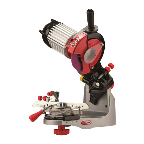
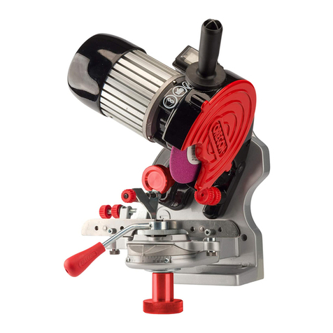
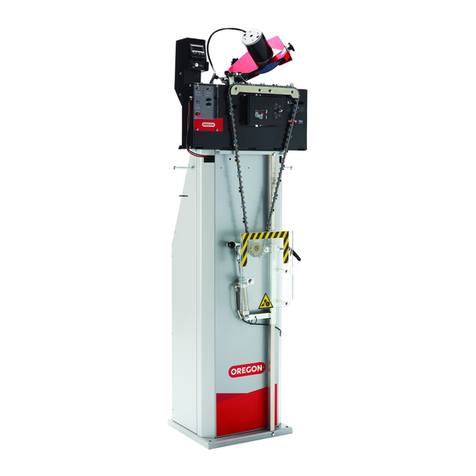
Oregon 760 User manual

Blade Sharpening Belt Grinder
Instruction Manual
For assembly, set up and operational use. 2 – 15
Meule à bande d’affûtage de lame
Mode D’emploi
Pour le montage, le réglage et l’utilisation. 16 – 29
Lijadora de banda de afilador
de cuchillas
Manual de Instrucciones
Para armado, instalación y uso operativo. 30 – 43
760
#88-100
#88-101
Read instructions thoroughly
before operating
Lire ces directives en entier
avant l’utilisation
Lea las instrucciones con atención
antes de utilizar el dispositivo
564916ab_760_Belt_Grinder_Manual.indd 1564916ab_760_Belt_Grinder_Manual.indd 1 5/7/20 11:32 AM5/7/20 11:32 AM

2
Operator and Operating Area Safety
Subject equipment includes grinders, buffers, polishers, and
other rotating equipment. Serious injury or death may occur
if minimum safety precautions are not understood and
obeyed by operators and those other persons who may be
in the immediate vicinity of the subject equipment. Persons
who operate or are in the immediate vicinity of the subject
equipment must be properly trained in, and use, appropriate
safety precautions and procedures for such machinery.
Personal protection equipment, such as grinding gloves,
hearing protection, and safety glasses must be worn when
using this equipment. Check with your company’s safety
officer for other safety requirements.
Never use this equipment if you are not properly trained
in its operation and safe use. If in doubt stop and ask for
guidance.
Minimum safety requirements
to operate or work in the
immediate vicinity:
1. Read and understand all operating instructions,
manuals, labels, and other information provided with the
equipment.
2. Install the equipment according to manufacturer’s
instructions.
3. Electrical installation must be in accordance with
applicable codes and regulations.
4. Securely bolt the equipment to a rigid, structurally sound
mounting surface.
5. Don’t expose the grinder to rainy, damp. or wet
locations. Don’t use the grinder if the power cord is
damaged or wet.
6. Do not wear loose clothing or jewelry. Non-skid
footwear is recommended when working with the
grinder. Wear protective hair coverings to contain long
hair. Wear proper safety equipment and clothing to
protect eyes, hands, face, arms, legs, feet, and body
from flying debris, forcibly ejected work pieces and
broken abrasive belts.
7. Use safety glasses. Everyday eyewear does not have
impact resistance lenses.
8. Do not use this equipment when tired, ill or under the
influence of alcohol or other drugs.
9. Review and understand all machine guards,
adjustments, and points of exposure to potential injury.
10. Do not remove, tamper with, or otherwise alter,
equipment guards and other safety features.
11. The use of stone or vitreous wheels on any Oregon® belt
grinder is prohibited. The grinder guarding is not suitable
for these types of wheels.
12. Ensure the machine is adjusted and remains adjusted
according to manufacture’s requirements.
13. Maintain the equipment in good operating condition.
14. Have another person who is knowledgeable in
proper and safe operation of the subject equipment
demonstrate proper and safe operation to all operators,
and to those persons who might be in the immediate
vicinity of the subject equipment.
15. Always wear gloves and use work piece holding devices
when ever possible that diminish the possibility that
persons will come in contact with moving machine
pieces, or spark/debris output from the machine.
16. Always keep electrical cords clear of rotating parts and
belts when in motion.
17. Do not use the grinder near flammable liquids or gases.
Sparks from the grinder can cause fires.
18. Use spark and debris arresting apparatus. Such
apparatus should be connected to the machine so as
to contain dust and debris that is generated, and to
suppress sparks thereby limiting human inhalation risk,
and the risk of fire or explosion.
19. Use appropriate inhalation apparatus to protect person
from ingestion and/or inhalation of sparks, debris,
smoke, particulates, etc.
20. Avoid mixing different metals, alloys, and
materials. To mix such materials might
create a fire or explosion hazard.
21. Protect persons from work pieces, particulates, etc.
that could be forcibly ejected from the machine. For
example, a buffing wheel or grinding belt can “grab”
a work piece while the work piece is being buffed,
polished, ground, or otherwise conditioned, resulting
in forcible ejection toward the operator or those in
the vicinity of the machine. The use of leather aprons,
gloves, and eye shields are examples of protective
gear that may be effective. In general do not grind, buff,
Safety Requirements
564916ab_760_Belt_Grinder_Manual.indd 2564916ab_760_Belt_Grinder_Manual.indd 2 5/7/20 11:32 AM5/7/20 11:32 AM

3
or otherwise engage the traveling belt, wheel, or disc
surface with the work piece pointing into the direction
from which the belt, wheel, or disc is traveling. However,
if you choose to do so, be aware the work piece may
lodge in the traveling belt, wheel, or disc and be forcibly
and dangerously ejected.
22. Do not operate this machine if the gap (nip point)
between a moving belt, wheel or disc, and the work
support surface exceeds 1/8 inch.
23. Do not operate this machine if the gap between the
moving abrasive belt, disc or wheel and the adjacent
face of the work rest (or table) will permit passage
of the work piece through the gap (nip point). Note,
however, that certain alloys such as titanium may create
conditions where grinding debris can accumulate in a
tight gap creating a potential fire hazard. When in doubt
consult with your safety officer. Failure to observe
this warning may result in the work piece or other item
being caught in this gap, and/or being forcibly ejected.
Failure to heed this warning may cause serious bodily
harm to the operator and/or bystanders.
24. Never position the work rest table at an acute angle
between the top of the work rest table and the moving
belt or wheel. Doing so will create “nip point” that can
cause serious injury should an operator body part
become entangled (pulled into) the nip point created by
this acute angle.
25. Do not operate the equipment or allow others to operate
the equipment without proper training in these and
other rotating machinery safety requirements.
26. Disconnect the power source when
the grinder is not in use.
27. Do not perform maintenance on the equipment unless
you are fully qualified to do so and understand all
necessary safety and operating requirements.
28. Do not leave the machine unattended while it is running.
29. Correct equipment or safety problems immediately.
Do not operate the equipment when it requires
maintenance or correction.
30. Install and use high quality abrasive belts, wheels,
discs, media, etc., as appropriate to your machine.
31. Understand and follow the operating requirements
provided by the manufacturer of these materials.
Rotational Speed Warning,
Contact Wheels
Scope: Contact wheels manufactured by Oregon®, which
have rubber or urethane tires. Examples include but are
not limited to stock codes 702, 702-S-90, 707, 707EX and
variants. Variants have stock codes that begin with the base
number; i.e. 802-S-55 is an 802 variant.
Users are warned not to exceed the below listed revolutions
per minute (RPM) on the subject wheels. Failure to heed
this warning may lead to tire de-bonding, fragmentation, or
other mechanical failure. Such failures may cause serious
personal injury to operators or bystanders, and/or cause
property damage.
Stock Code Maximum Rpm
707-S-90 4,400
Occupational Noise Exposure
Oregon products produce levels of noise consistent with
their intended purposes. The level and spectral content of
noise produced is dependent on the product type, the degree
that the product is maintained in proper operating condition,
the abrasive/media and accessories used, the specific
application, and the surrounding environment.
Noise levels produced by various Oregon grinders, as
measured at the factory, range from 80 to 93 decibels.
Product operators and persons in the immediate product
vicinity should be protected from excessive noise dose
levels as prescribed in OSHA regulation 29CFR Part 1910.95
titled “Occupational Noise Exposure”.
WARNING: Rotating equipment can be
dangerous to operators and those who may
be in its immediate operating vicinity. It is the
absolute and direct responsibility of purchasers, managers,
and operators of this equipment to understand and obey the
foregoing minimum operating safety requirements.
Oregon disclaims any and all responsibility for injuries,
damage, loss of income, or other adverse consequence as
might be incurred by purchasers, managers, and operators
of this equipment.
If you have questions or safety concerns regarding
operating the subject equipment please call your authorized
Oregon distributor, or Oregon Outdoor Equipment Parts,
Oregon®, Blount, Inc., 4909 SE International Way,
Portland, Oregon 97222, 800-223-5168, or you can contact
us by email at technicalservices@OregonProducts.com
Safety Requirements
564916ab_760_Belt_Grinder_Manual.indd 3564916ab_760_Belt_Grinder_Manual.indd 3 5/7/20 11:32 AM5/7/20 11:32 AM
4
AVOID INJURY:
Operator safety and the continued effectiveness of your
model 760 requires that you:
+Do not defeat the safety guards and other
safety provisions of the model 760.
+Do not operate the model 760 with the safety guard
open or the contact wheel guard/platen assembly
(or internal grinding attachment) removed.
+Do not reach inside the safety guards while the
machine is running. To do so is hazardous.
+Do not use fluids in your grinding process
unless your model 760 is designed for
liquid operation. (NEMA 4, 4X). To do so
may create an electrical safety hazard.
+Do not use your model 760 to grind/polish
explosive materials unless it is equipped with
explosion proof electrical devices and motor.
+Do not mix alloys in your grinding. To do so
may create an explosion/fire hazard.
+Do not use stone or vitreous wheels on the model
760. To do so will create an operator safety hazard.
+Do use eye, hand, face, arm, leg, feet and
body protection that is adequate to protect
against flying debris, forcibly ejected work
pieces, broken abrasive belts, etc.
+Do train operators and others in
safe operating practices.
POST THESE OR EQUIVALENT INSTRUCTIONS SUCH
THAT THEY ARE AVAILABLE FOR READY OPERATOR
REFERENCE.
Warning
564916ab_760_Belt_Grinder_Manual.indd 4564916ab_760_Belt_Grinder_Manual.indd 4 5/7/20 11:32 AM5/7/20 11:32 AM

5
Available Parts
Please refer to the parts drawing when ordering parts. Not all
components of the Grinder are replacement items, but are illustrated
as a convenient reference for location. When ordering parts, give Model
number, serial number and description.
Call or write for current pricing:
Oregon Outdoor Equipment Parts, Oregon®, Blount, Inc.
4909 SE International Way, Portland, Oregon 97222, 800-223-5168, or
you can contact us by email at technicalservices@OregonProducts.com
1
9
3
11
10
4
7
5
6
8
2
Item Part No. Description
1
88-111 Abrasive Belt, 1-1/2" x 60" 36 g
88-112 Abrasive Belt, 1-1/2" x 60" 120 g
2
011DKIT On/Off Toggle Switch
011C On/Off Rocker Switch
3O-703-3 Contact Wheel Guard
4728 V-Belt Guard
5O-742A-1 Safety Guard
6575377 AC 1.5 hp Motor with Cord & Switch
7737A Tensioning Handle
8711 Tracking Adjustment Knob
9O-704-1 Vertical Platen
10 9609KIT Mower Blade Table
11 88-104 Serrated Contact Wheel
Product Description
564916ab_760_Belt_Grinder_Manual.indd 5564916ab_760_Belt_Grinder_Manual.indd 5 5/7/20 11:32 AM5/7/20 11:32 AM

6
The model 760 belt grinder is a three wheel path
belt grinder that uses a 1-1/2" x 60" continuous loop
abrasive belt. For maximum effectiveness and
operator safety, use abrasive belts manufactured
by well respected abrasive manufacturers.
Use abrasive belts that are the proper
size and type for your machine.
Do not use abrasive belts that are old or excessively worn.
Do not use abrasive belts that use lap splice joints.
Lap spliced belts are prone to separation. They
may also tend to snag your work and create a
potential safety hazard by snagging and propelling
the work part in the operator’s direction.
Prior to operating the model 760 please take time to do the following:
1. Ensure that you have received all of the items that you
ordered. Compare the packing slip with your purchase
order, and of course with the physical items received.
2. Verify that there is no obvious shipping damage.
If shipping damage is discovered notify the
freight carrier of your intention to file a freight
damage claim. They will assist you.
3. Verify that the AC power that is identified on the
machine as received matches the AC power
that you intend to operate the machine with. Do
not modify the machine’s wiring without first
contacting your distributor and/or Oregon.
4. Do not modify or defeat any AC wiring safety feature.
Never remove the grounding pin on the AC plug.
5. Verify that you have received an Instruction Manual.
6. Verify that the various guards for the machine are in
place and functional. (See illustration, pg. 5.)
a. The contact wheel guard and vertical platen are
mounted and adjusted such that the platen lightly
touches the back of the abrasive belt (Figure 1).
See page 7 for complete instructions on
installation.
b. The full safety guard is in place, closed, and its
door latch is functional such that it will securely
hold the safety door closed. (Figure 2).
7. Prior to operating the model 760 carefully
read the Instruction Manual. Ensure that all
persons who will operate the model 760, or who
will work in the vicinity of the model 760 read
understand, and comply with these instructions.
8. Ensure that the grinder is located in an area that
provides clear access to the machine such that
operators have safe and unobstructed access
to the machine. The work place should be free
from floor obstructions, trip points, and other
faults that may reduce operator safety.
9. Oregon recommends that all three phase installations
include a magnetic starter. Magnetic starters
protect motors from “single phasing”, overheating,
etc. thereby reducing the risk of damage to the
equipment and/or fire hazard to your facility.
10. Ensure that the model 760 AC power source
is properly sized, and properly fused. You
should consult a competent electrician, or
you may call Oregon for guidance.
1Contact Wheel Guard
2Vertical Platen
3Abrasive Belt
4Safety Guard Door
5Door Latch
Figure 1 Figure 2
3
1
24
5
BEFORE OPERATING ANY EQUIPMENT PLEASE READ
AND REVIEW ALL SAFETY INSTRUCTIONS FOR THE
OREGON® MODEL 760.
PERSONAL PROTECTION EQUIPMENT, SUCH AS GRINDING
GLOVES, HEARING PROTECTION, AND SAFETY GLASSES
MUST BE WORN WHEN USING THIS EQUIPMENT. CHECK
WITH YOUR COMPANY’S SAFETY OFFICER FOR OTHER
SAFETY REQUIREMENTS.
WARNING:
Use caution when liing grinder. Use two people when
removing from shipping box.
Before Use
564916ab_760_Belt_Grinder_Manual.indd 6564916ab_760_Belt_Grinder_Manual.indd 6 5/7/20 11:32 AM5/7/20 11:32 AM

7
Mounting
Your machine has been assembled and passed
numerous quality checks prior to shipping. The
mower blade attachment is fully assembled.
1. Open wheel cover door and remove contact
wheel with 15/16" socket wrench. (Figure 3)
2. Rotate table support arm to the down position.
3. Using a 7/16" wrench and 5/32" Allen wrench,
remove table support arm bolt and attach the
support bar to the table support arm.
4. Using a 3/16" Allen wrench, tighten
table support arm bolt.
5. Using a 3/16" Allen wrench, remove two screws
from table support arm mounting block and attach
mower blade support table. Tighten securely,
making sure to place washers on the outside of
bracket on mower blade support table. (Figure 4)
6. Replace contact wheel with 15/16" socket.
It will be a tight fit, so proceed carefully and use
a little lubricating oil if needed.
Installing The Belt
7. Install the 36 grit belt over all three wheels and
tension belt by pivoting tension knob upwards.
8. Pivot vertical platen into position so belt is
gently touching the vertical platen. Tighten the
3/16" Allen screws to secure the vertical platen
to the bearing housing.
9. Ensure that the abrasive belt is tensioned properly.
To do this, raise the tensioning handle (Figure 5).
You will hear mechanical clicks as the tensioning
ratchet moves. Generally, the belt will be adequately
tensioned when you hear three to eight clicks. To
reduce or release the belt tension slightly raise
the tensioning handle then press the button in
the center of the tensioning handle. Move the
tensioning handle down slightly to reduce belt
tension or all the way down to release belt tension.
10. Rotate belt by hand to center belt on wheels.
11. Close wheel cover door.
12. Attach chain saw bar grinding table with two bolts
to the vertical platen. (Figure 6).
Adjusting the Attachment
Unlike a stone grinder, the diameter of the contact wheel
will remain nearly the same the entire life of the wheel.
Since the diameter of the wheel also will remain constant
you will rarely need to adjust the table height. Another
advantage of using a belt to grind metal versus a stone
is when a stone reduces in diameter, you lose surface
speed, making grinding times increase. A stone wheel
may turn at 6,000 surface feet per minute when it’s brand
new, but aer limited use the diameter of the stone will
decrease and the result will be increased sharpening
times and the stone will retain more heat.
89
43
5
2
1
6
7
Lawn Mower Blade
Sharpener Attachment
1Contact Wheel
2Contact Wheel Nut
3Table Support Arm
4Mower Blade Support Table
5Table Support Bar
6Tensioning Handle
7Tensioning Handle Button
8Chain Saw Bar Grinding Table
9Vertical Platen
4
8
Figure 3
Figure 5
Figure 4
Figure 6
564916ab_760_Belt_Grinder_Manual.indd 7564916ab_760_Belt_Grinder_Manual.indd 7 5/7/20 11:32 AM5/7/20 11:32 AM

8
Checking the grinder
The model 760 was fully tested and verified to
comply with requirements prior to shipping from
the factory. You should perform the following steps:
1. Adjust the work support and work support arm to the
desired position with the Attachment Locking Lever
(Figure 7). Take care that the gap between the face
of the abrasive belt and the work rest is at most 1/8
inch. WARNING: Be aware that thin section work
pieces can pass through this gap if the gap is not
properly adjusted. Ejected work parts can cause
serious personal injury!
2. With the machine securely bolted to its table,
pedestal, and/or floor point connect the AC power to
its source.
3. Engage the motor by placing the ON/OFF switch
to ON. The belt should rotate smoothly in a
counterclockwise direction around the machine wheel
belt path. If either of these conditions is not met
immediately turn the machine OFF.
a. If the abrasive belt does not remain centered on
the contact wheel while the belt is moving use the
Tracking Adjustment Knob (Figure 8) on the upper
le side of the machine to track the belt. Turn this
control clockwise to cause the belt to track to the
le; conversely, turn the control counterclockwise to
cause the belt to move to the right.
b. If the belt runs in reverse (up from the floor) you
must correct this unsafe condition by changing the
main drive motor rotation direction.
(See instructions below.)
c. If the abrasive belt tensions and tracks properly,
but has excessive vibration, turn the machine
off and call Oregon® for assistance.
Always unplug the machine before performing any
adjustments to the work platforms.
4
23
1
Operation
1Work Support
2Work Support Arm
3Attachment Locking Lever
4Tracking Adjustment Knob
Figure 7 Figure 8
WARNING: First disconnect the machine
from its ac power source. A competent
electrician should perform all electrical work
on the model 760.
1. Reverse the motor direction of a three phase motor
by reversing any two legs of the input power lines.
2. Reverse the motor direction of a single phase
motor by reversing leads 5 and 8 found within
the metal wiring box located on the motor, or as
otherwise instructed on the actual motor label.
564916ab_760_Belt_Grinder_Manual.indd 8564916ab_760_Belt_Grinder_Manual.indd 8 5/7/20 11:32 AM5/7/20 11:32 AM

9
Maintenance
+ Every thirty days apply light machine oil to the rear wheel support and
the Tension Arm Interface. (Figure 9) Two drops of oil is sufficient.
+ Every thirty days check the v-belt tension. If you can hear the belt
“slap” the V-belt Guard (Item 4, page 5) when the drive motor
starts, the v-belt requires re-tensioning. Do this by loosening the four
bolts (Figure 10) that secure the motor to the machine base and slide
the motor toward the rear of the machine. Tighten the four bolts.
+ Vacuum daily or otherwise remove dust and debris build-
up from the machine and the machine belt track.
There are no other maintenance actions required. All bearings
are sealed for life and require no additional lubrication.
3
1
2
4
5
Operation
WARNING: Disconnect the machine from
its AC power source before beginning any
maintenance.
Figure 10Figure 9
1
Rear Wheel Support and
Tension Arm Interface
(Inside Housing Below
Tensioning Handle)
2Tensioning Handle
3Tensioning Button
4V-Belt Guard
5Four Motor Bolts
564916ab_760_Belt_Grinder_Manual.indd 9564916ab_760_Belt_Grinder_Manual.indd 9 5/7/20 11:32 AM5/7/20 11:32 AM

10
Aligning Idler Wheels
When idler wheels are removed and/or replaced they must
be installed such that they are in proper alignment. Failure
to properly align the idler wheels will result in premature
failure of the wheels. Premature failure will be evidenced
by outer diameters being excessively worn such that the
wheels lose their factory crown, wear to a truncated form,
or become out of balance. Misalignment results in wear
that is analogous to front tire wear when the front steering
mechanism of an automobile is misaligned. The upper
idler equates to the front wheels of the car. If either idler
wheel is misaligned to each other or to the contact wheel,
excessive and irregular wear will occur.
The upper and rear idler wheels must operate in the same
plane. This means that when they are correctly aligned a
plane passing through the radial center of the upper wheel
will exactly pass through the radial center of the rear
wheel. Machines are shipped from the factory with wheels
of the same width. Currently, model 760 machines are
shipped with wheels that are 1.5 inches wide.
1. Disconnect electric power and remove the abrasive belt.
2. Install the rear idler such that its inside bearing
surface is approximately 0.06 inches out
from the wheel support. Secure the wheel
with locking set screw. (Figure 11)
3. Install the upper wheel such that its inner
bearing surface is approximately 0.06 inches
out from its bearing support. Secure the
wheel with locking set screw. (Figure 12)
4. Loosen the retaining nut that locks the upper idler
wheel adjusting screw. (Figure 13) Using screw
adjust the upper idler wheel until a straight line
representing the plane passing through the center
of the upper idler exactly passes through the
center of the contact wheel. This line represents
the center of belt travel. Note: make certain that
the bearing support is against the screw end.
5. Project a line from the upper idler outside rim to
the outside rim of the rear idler. Adjust the tracking
adjustment knob until the wheels are exactly
planar. That is, their radial centers are aligned.
6. Repeat step 3 and 4 until both conditions are satisfied.
That is, the upper and rear idlers are aligned to each
other and both wheels are aligned to the contact wheel.
7. Tighten the locking nut on the upper
idler wheel adjusting screw.
8. Install a new abrasive belt. Roll the belt manually
to assure that it will maintain coarse tracking. If
the belt does not track manually, repeat the prior
steps until it does. If aer repeating these steps the
belt still will not track, the machine requires other
maintenance and/or one or both idler wheels require
replacing. The wheels should be replaced in pairs.
9. Apply electric power to the machine and verify
that the tracking adjustment knob (Item 8,
pg. 5) will sweep the belt across the face of
the contact wheel. At least ½-inch adjustment in
both directions from center should be possible.
1
2
3
5
4
Operation
Figure 11
Figure 13
Figure 12
1
Locking Set Screw,
Rear Idler Wheel
2Upper Wheel
3
Locking Set Screw,
Upper Idler Wheel
4
Retaining Nut,
Upper Idler Wheel
55/32" Allen Wrench
WARNING: Never perform maintenance or
adjustments on your model 760 without first
disconnecting the machine from its source of
electric power.
Failure to observe this warning may lead to serious
personal injury.
564916ab_760_Belt_Grinder_Manual.indd 10564916ab_760_Belt_Grinder_Manual.indd 10 5/7/20 11:32 AM5/7/20 11:32 AM

11
Sharpening
MOWER BLADES
Free the blade of any grease,
dirt, or clippings prior to
sharpening. Check the blades to make sure they are not
bent or cracked. Using a blade balancer, check the blade for
its balance. When sharpening start by grinding the light end
of the blade and then follow with the heavy end.
Move the blade in one direction only. Assuming that
you have a standard mower blade, your direction
would be from le to right. Rest blade on table, gently
move blade into rotating wheel and draw the blade to
the right. Multiple passes are required to achieve the
edge desired. Minimal pressure to the contact wheel is
recommended. The idea is to have the belt do the cutting,
not by using force against the contact wheel. Make rapid
passes, each pass should only take seconds in total
time. If you are not moving the blade across the wheel
in a rapid fashion, you will create hot spots in the blade,
and the blade will not move easily across the wheel.
Aer sharpening the first edge, use the slack area
of the belt to remove any burrs that may have been
created in the sharpening procedure. Next, move to
the second edge and repeat the procedure. Check the
balance of the blade to ensure proper stock removal.
MULCHING BLADE
SHARPENING
Remove the vertical platen by
removing the two Allen bolts that attach it to the contact
wheel guard. It is important to readjust the contact wheel
guard to remove the pinch point created by removing the
platen. By removing the platen you create a large “slack”
free belt area. By using a flexible back belt (J weight) or a
narrow stiff back belt you will be able to use the slack area
to sharpen the blade. The operator will freehand the desired
angle. Aer sharpening the first edge, use the slack area of
the belt to remove any burrs that may have been created in
the sharpening procedure. Next, move to the second edge
and repeat the procedure. Check the balance of the blade to
ensure proper stock removal.
ROTARY-STYLE
OFFSET FLAIL BLADE
SHARPENING
Free the blade of any foreign
substances. Depending on style of the blade, balancing the
blade maybe different than described in this manual. Most
rotary blades can be balanced using a simple balance-style
scale. Since there is no other way to check for balance due
to the offset hole style of the blades, use of a scale is to
make sure that the blades are all equal in mass. Using a
scale allows you to make sure each blade weighs the same
amount, keeping the blades in balance.
You may also choose to check the blades using a standard
scale. Once again, start with the lightest blade and then
sharpen the heavier blade, checking the blades for balance.
Attach the galvanized tubing (Item 6, page 12) to the
worktable, using two button head black oxide screws
(Item 14, page 12) and two kep nuts (Item 8, page 12).
This changes the angle for the rotary-style blade to a
factory recommended angle. As with mower blades, it is
recommended to move the blade in one direction only.
If the blade has deep chips, use the contact wheel to
“face the blade.” Move up on the contact wheel a couple
of inches to the centerline and run the blade back and
forth several times to even the edge of the blade. Next
you will rest the blade against the tubing and start the
sharpening process. Again, use only light inward pressure.
The belt and speed of the belt will do all the work for you.
CHIPPER BLADE
SHARPENING
Free the blade of any foreign
substances. Depending on
style of the blade, balancing the blade maybe different than
described in this manual. Most chippers require all blades to
be the same height. Start with the shortest blade and use it
for a reference, then move on to the others in the set.
Only sharpen blades that are long and wide
enough to safely hold on to. As with any
sharpening process on the grinder move only in
one direction and apply minimal inward force.
Grinding Belts
Oregon® recommends using only a 3M or Norton
24 or 36 grit ceramic belts to sharpen blades using
the blade attachment (Norton Blaze R980). These
belts contain cooling aids and are constructed
for heavy stock removal. Replacement belts can
be ordered from your Oregon distributor.
Remove any burrs on the back of the blade by
making a couple of passes on the slack portion
of the belt. This will reduce the effort required
when moving the blade across the table.
Lawn Mower Blade Sharpening
WARNING: If a belt is damaged or
shows excessive wear, immediately
stop use of the belt and discard it.
564916ab_760_Belt_Grinder_Manual.indd 11564916ab_760_Belt_Grinder_Manual.indd 11 5/7/20 11:32 AM5/7/20 11:32 AM

12
Available Parts
Please refer to the parts drawing when ordering
parts. Not all components of the attachments are
replacement items, but are illustrated as a convenient
reference of location and position in the assembly
sequence. When ordering parts, give grinder model
number, part number and description of part.
Call or write for current pricing:
Oregon®, Blount, Inc.
4909 SE International Way
Portland, Oregon 97222
800-223-5168
or you can contact us by email at
technicalservices@OregonProducts.com
Replacement Parts
13
10
1
16
14
6
10
8
4
7
17
3
5
11
12
8
2
15
9
Item Part
No. Description Qty.
1O-9607 Workrest Support Arm 1
29610 Arm Bracket 1
39606 Guide Block 1
49609A Workrest Assembly 1
59605 Alignment Plate 1
69602 Angle Tube 1
75-0047 Flathead Screw, 1/4"-20 x 1-1/4" 1
84-0013 Kep Nut, 1/4"-20 3
9209 Allen Head Screw, 1/4"-20 x 3/4" 2
10 5 Washer, 1/4" 3
11 15 Washer, #10 LOCK, Split 4
12 9Button Head Black Oxide Screw,
10-24 x 1/2" 4
13 31 Screw, 1/4"-20 x 1-1/4" 1
14 2-0014 Button Head Screw, 1/4"-20 x 1/2" 2
15 4-0009 Jam Nut, 5/16"-18 1
16 2-0064 Shoulder Screw, 3/8" x 1-1/2" 1
17 1203-2 Handle-Locking 1
Model 760
MOWER BLADE ATTACHMENT
564916ab_760_Belt_Grinder_Manual.indd 12564916ab_760_Belt_Grinder_Manual.indd 12 5/7/20 11:32 AM5/7/20 11:32 AM

13
1
3
4
7
8
5
6
2
Part #88-116
CHAIN SAW BAR GRINDING ATTACHMENT
Replacement Parts
Item Part
No. Description
19603 Chain Saw Bar Grinding Platen
2O-9604 Aluminum Block
3O-704-1 Platen Bracket
46-0001 Roll Plated Pin, 3/16" x 1"
56 Flathead Screw, 1/4"-20 x 1-1/2"
613 Cap Head Allen Screw, 10-24 x 3/4"
75-0049 High Collar Lock Washer, #10
84-0013 Kep Nut, 1/4"-20
564916ab_760_Belt_Grinder_Manual.indd 13564916ab_760_Belt_Grinder_Manual.indd 13 5/7/20 11:32 AM5/7/20 11:32 AM
14
The Oregon® customer-satisfaction
policy limited warranty
Oregon® | Blount, Inc. Warrants its products to be free from
defects in materials and workmanship for as long as they
are owned by the original retail purchaser.
If you like our products, please tell your friends. If you are
not satisfied with our products, for any reason, please tell
us. Oregon wants to provide you with products that perform
to your full satisfaction. We welcome you to contact us as
shown in the last paragraph.
Liability under this warranty is limited to replacement parts,
at the option of your Oregon distributor and Oregon. Please
contact your Oregon distributor or us directly. Oregon
products are not warranted against normal wear and tear,
user abuse, improper maintenance or improper repair.
Replacement of defective product is the exclusive remedy
under this warranty and any applicable implied warranty.
The replacement will be undertaken as soon as reasonably
possible aer receipt of the defective product. To the extent
permitted by law, any implied warranty of merchantability or
fitness for a particular purpose applicable to this product is
limited to the duration and scope of this express warranty.
Oregon shall not be liable for any consequential or incidental
damages. Some states do not allow limitations on how long
an implied warranty lasts or do not allow the exclusion of
consequential damages, so the above limitation or exclusion
may not apply to you. This warranty gives the original owner
specific legal rights, and you may also have other rights
which vary from state to state.
To contact us in the U.S.A. regarding Oregon outdoor
equipment parts (lawnmower blades and replacement parts
for small engines, lawnmowers and many other types of
outdoor power equipment), we welcome your calls between
the hours of 7:30 a.m. and 4:30 p.m. (PST), Monday through
Friday at 800-223-5168, or you can write to:
Technical Services Department
Oregon Outdoor Equipment Parts
Oregon®, Blount, Inc.
4909 SE International Way, Portland, Oregon 97222
or you can contact us by email at
technicalservices@OregonProducts.com.
Warranties
564916ab_760_Belt_Grinder_Manual.indd 14564916ab_760_Belt_Grinder_Manual.indd 14 5/7/20 11:32 AM5/7/20 11:32 AM

15
Notes
564916ab_760_Belt_Grinder_Manual.indd 15564916ab_760_Belt_Grinder_Manual.indd 15 5/7/20 11:32 AM5/7/20 11:32 AM
16
Sécurité de l’opérateur et
de la zone d’utilisation
Les équipements couverts dans ce manuel incluent les affûteuses,
les ponceuses, les polisseuses et les autres équipements rotatifs.
De graves blessures et la mort peuvent survenir si un minimum
de précautions de sécurité ne sont pas comprises et suivies par
les opérateurs et les autres personnes se trouvant dans la zone
de l’équipement. Les personnes qui utilisent ou qui se trouvent
près de l’équipement doivent avoir reçu une formation appropriée
et appliquer des précautions de sécurité ainsi que suivre les
procédures prévues pour la machinerie.
Les équipements de protection individuelles tels que des
gants d’affûtage, des dispositifs de protection pour les
oreilles et des lunettes de sécurité doivent être portés lors
de l’utilisation de cet équipement. Informez-vous auprès de
la personne responsable de la sécurité de votre entreprise
au sujet des autres exigences de sécurité.
Ne jamais utiliser l’équipement si une formation appropriée
sur son fonctionnement et son usage sécuritaires n’a pas
été suivie. En cas de doute, arrêter le travail et demander
des conseils.
Voici les exigences de sécurité
minimum pour l’utilisation ou le
travail à proximité de l’équipement :
1. Lire et s’assurer de comprendre toutes les directives
d’utilisation, les manuels, les étiquettes ainsi que les
autres renseignements fournis avec l’équipement.
2. Installer l’équipement conformément
aux directives du fabricant.
3. L’installation électrique doit être conforme
aux codes et règlements applicables.
4. Fixer solidement l’équipement à une surface de
montage rigide ayant une structure fiable.
5. Ne pas exposer la meule à la pluie ni
utiliser la meule dans un endroit humide ou
mouillé. Ne pas utiliser la meule si le cordon
d’alimentation est endommagé ou mouillé.
6. Ne pas porter de vêtements amples ni de bijoux. Il est
recommandé de porter des chaussures antidérapantes
lors du travail avec la meule. Porter des dispositifs
de protection pour les cheveux qui peuvent contenir
les cheveux longs. Porter des équipements et des
vêtements de sécurité appropriés pour protéger les
yeux, les mains, le visage, les bras, les jambes, les pieds
et le corps contre les débris projetés, des morceaux
éjectés avec force et des bandes abrasives cassées.
7. Utiliser des lunettes de sécurité. Les lunettes régulières
ne sont pas dotées de lentilles qui résistent aux impacts.
8. L’opérateur ne doit pas utiliser cet équipement lorsqu’il
est fatigué ou sous l’influence de l’alcool ou de drogue.
9. Réviser et s’assurer de bien comprendre tous
les dispositifs de protection de la machine,
les ajustements et les points d’exposition
potentiels pouvant entraîner des blessures.
10. Ne pas enlever, ni modifier de quelque
façon les dispositifs de protection et les
autres caractéristiques de sécurité.
11. Il est interdit d’utiliser des meules en pierre
ou en vitre sur toute meule à bande Oregon®.
Les dispositifs de protection de meule ne
conviennent pas à ces types de meules.
12. S’assurer du bon ajustement et du maintien de
l’ajustement conformément aux exigences du fabricant.
13. Garder l’équipement en bon état d’utilisation.
14. Demander à une personne connaissant l’utilisation
appropriée et sécuritaire de l’équipement de
démontrer l’utilisation appropriée et sécuritaire
à tous les opérateurs ainsi qu’aux personnes qui
pourraient se trouver à proximité de l’équipement.
15. Porter toujours des gants et utiliser des pièces de
retenue lorsque c’est possible afin de réduire le risque
que ces personnes ne viennent en contact avec
des pièces mobiles de la machine ou des étincelles
et des débris en provenance de la machine.
16. Garder toujours les cordons électriques à l’écart des
pièces rotatives et des bandes en mouvement.
17. Ne pas utiliser la meule près de liquides ou de
gaz inflammables. Des étincelles provenant de
la meule peuvent provoquer un incendie.
18. Utiliser un dispositif d’arrêt d’étincelles et de débris. Ces
appareils doivent être connectés de façon à contenir la
poussière et les débris générés et d’éliminer les étincelles
en limitant ainsi le risque d’inhalation par des personnes
ainsi que le risque d’un incendie et d’une explosion.
19. Utiliser un appareil d’inhalation approprié pour
protéger les personnes contre l’ingestion et l’inhalation
d’étincelles, de débris, de fumées et de particules.
20. Éviter de mêler différents métaux, alliages et
matériaux. Le mélange de ces matériaux peut
provoquer un risque d’incendie et d’explosion.
21. Protéger les personnes des pièces, des particules, etc. qui
pourraient être éjectées de la machine. Par exemple, une
meule à polir ou une meule à bande peut «emprisonner»
une pièce pendant qu’elle est affûtée, polie, meulée ou
autrement travaillée en entraînant une éjection forte vers
l’opérateur ou les personnes se trouvant à proximité.
Utiliser un tablier en cuir, des gants et des dispositifs de
protection pour les yeux sont des exemples de dispositifs
de protection pouvant être efficaces. De façon générale,
ne pas affûter, poncer ou engager autrement une surface
de bande, de meule ou de disque en mouvement avec une
Exigences de sécurité
564916ab_760_Belt_Grinder_Manual.indd 16564916ab_760_Belt_Grinder_Manual.indd 16 5/7/20 11:32 AM5/7/20 11:32 AM
17
pièce travaillée en direction du déplacement de la bande,
de la meule ou du disque. Cependant, si l’opérateur
décide de le faire, il doit être conscient que la pièce
peut se loger dans la bande, la meule ou le disque en
mouvement et être éjectée dangereusement avec force.
22. Ne pas utiliser cette machine si l’intervalle (point
de pincement) entre une bande, une meule ou un
disque et la surface de support excède 3,175 mm.
23. Ne pas utiliser cette machine si l’intervalle entre la
bande, la meule ou le disque abrasif et la surface
adjacente à la surface d’appui (ou la table) permet le
passage de la pièce par l’intervalle (point de pincement).
Prendre note que certains alliages tels que le titane
peuvent créer des conditions dans lesquelles les débris
de meulage s’accumulent dans un intervalle restreint
en créant un risque d’incendie. En cas de doute,
s’informer auprès de la personne responsable
de la sécurité. Manquer de se conformer à cet
avertissement peut entraîner l’emprisonnement de la
pièce travaillée ou d’autres éléments dans cet intervalle
et une éjection avec force. Manquer de tenir compte
de cet avertissement peut entraîner des blessures
graves à l’opérateur et aux personnes environnantes.
24. Ne jamais placer la table d’appui à un angle aigu entre
le haut de la table d’appui et la bande ou la meule en
mouvement. Cela entraînerait un point de pincement
qui peut provoquer des blessures graves si une partie
du corps de l’opérateur se faisait prendre (attiré)
dans le point de pincement créé par l’angle aigu.
25. Ne pas utiliser ni ne laisser d’autres personnes
utiliser cet équipement sans avoir reçu une formation
appropriée préalable sur ces exigences ainsi que les
autres sur la sécurité reliée aux machineries rotatives.
26. Déconnecter la source d’alimentation
lorsque la meule n’est pas utilisée.
27. Ne pas effectuer d’entretien sur l’équipement
à moins d’être qualifié pour le faire et d’être
assuré de bien comprendre toutes les exigences
de sécurité et d’utilisation pertinentes.
28. Ne pas laisser la machine sans surveillance
lorsqu’elle est en marche.
29. Corriger immédiatement tout problème d’équipement
ou de sécurité. Ne pas utiliser la machine lorsqu’elle
nécessite de l’entretien ou une correction.
30. Installer et utiliser des bandes, meules, disques abrasifs
et autres de haute qualité convenant à la machine.
31. S’assurer de comprendre et de suivre toutes les exigences
d’utilisation fournies par le fabricant de ces équipements.
Avertissement relié à la vitesse de
rotation, roues de contact
Portée : Les roues de contact fabriquées par Oregon
sont dotées de pneus en caoutchouc ou en uréthane.
Par exemple, les codes de stocks 702, 702-S-90,
707, 707EX et les variantes. Les variantes ont des
codes de stock qui commencent par le numéro de
base, par exemple 802-S-55 est une variante 802.
Nous avertissons les utilisateurs de ne pas excéder
le nombre de tours par minute (tr/min) des meules.
Manquer de tenir compte de cet avertissement peut
entraîner un décollement, une fragmentation ou une
autre défaillance mécanique. Ces défaillances peuvent
entraîner des blessures graves à l’opérateur ou aux
personnes environnantes ainsi que des dommages.
Code de stock TR/Min Maximum
707-S-90 4,400
Exposition aux bruits sur
le lieu du travail
Les produits Oregon produisent des niveaux de bruit
correspondant à leurs utilisations prévues. Le niveau et le
contenu du spectre de bruit produit dépendent du type de
produit, du degré auquel le produit est gardé en bon état
d’utilisation, le type d’abrasif et les accessoires utilisés,
l’application spécifique et le milieu environnant.
Les niveaux de bruits produits par différentes meules
Oregon, tels que mesurés à l’usine s’échelonnent de 80
à 93 décibels. Les opérateurs de produit ainsi que les
personnes se trouvant à proximité doivent se protéger
contre les niveaux de bruits excessifs tel que prescrit
dans le règlement de l’OSHA 29CFR Partie 1910.95 intitulé
Exposition aux bruits sur le lieu du travail.
AVERTISSMENT :
Les équipements
rotatifs peuvent présenter des dangers pour
les opérateurs et les personnes se trouvant à
proximité. Les acheteurs, les directeurs et les opérateurs
de cet équipement ont la responsabilité directe et absolue
de s’assurer de bien comprendre et de se conformer aux
exigences de sécurité minimum lors de l’utilisation.
Oregon se dégage de toute responsabilité reliée à des
blessures, des dommages, des pertes de revenus
ou d’autres conséquences néfastes pouvant toucher
les acheteurs, les directeurs et les opérateurs de cet
équipement.
Si vous avez des questions ou des préoccupations reliées
à la sécurité de l’utilisation de l’équipement, veuillez
téléphoner à votre distributeur autorisé Oregon, ou à
Technical Services Department, Oregon Outdoor Equipment
Parts, Oregon®, Blount, Inc., 4909 SE International Way,
Portland, Oregon 97222, au 800-223-5168 et vous pouvez
aussi nous envoyer un courriel à technicalservices@
OregonProducts.com.
Safety Requirements
564916ab_760_Belt_Grinder_Manual.indd 17564916ab_760_Belt_Grinder_Manual.indd 17 5/7/20 11:32 AM5/7/20 11:32 AM

18
ÉVITER LES BLESSURES :
La sécurité de l’opérateur et la continuité de
l’efficacité de votre modèle 760 exigent de :
+Ne pas modifier les gardes de sécurité et les
autres dispositifs de sécurité du modèle 760.
+Ne pas utiliser le modèle 760 alors qu’une
garde de sécurité est ouverte ou que la garde/
plateau de la roue de contact (ou l’accessoire
de meulage interne) est retiré(e).
+Ne pas passer les mains à travers les
gardes de sécurité lorsque la machine est
en marche. Cela pourrait être dangereux.
+Ne pas utiliser de fluides dans le processus
d’affûtage à moins que le modèle 760 ne
soit conçu pour un fonctionnement avec des
liquides. (NEMA 4, 4X). Cela pourrait créer un
risque de sécurité de nature électrique.
+Ne pas utiliser le modèle pour affûter/
polir des matériaux explosifs à moins qu’il
ne soit doté de dispositifs électriques et
d’un moteur à l’épreuve des explosions.
+Ne pas mêler des alliages pour l’affûtage. Cela
pourrait créer un risque d’explosion et d’incendie.
+Ne pas utiliser de meules en pierre ou en
vitre sur le modèle 760. Cela pourrait entraîner
un risque de sécurité pour l’opérateur.
+Porter des équipements de protection pour
les yeux, les mains, le visage, les bras, les
jambes, les pieds et le corps appropriés contre
les débris projetés, des morceaux éjectés avec
force, des bandes abrasives cassées, etc.
+Former les opérateurs et les autres
personnes concernées sur les pratiques
d’utilisation sécuritaires.
AFFICHER CES DIRECTIVES OU AUTRES
DIRECTIVES ÉQUIVALENTES DE SORTE
QU’ELLES SOIENT DISPONIBLES À DES FINS
DE RÉFÉRENCE RAPIDE POUR L’OPÉRATEUR.
Avertissement
564916ab_760_Belt_Grinder_Manual.indd 18564916ab_760_Belt_Grinder_Manual.indd 18 5/7/20 11:32 AM5/7/20 11:32 AM
19
Pièces disponibles
Veuillez vous référer aux schémas des pièces lors de la passation de
commande. Les composants de la meule ne sont pas tous remplaçables,
mais ils sont tous illustrés à titre de référence pratique pour déterminer
leur emplacement. Lors de la passation de la commande, veuillez indiquer
le numéro de modèle, le numéro de série ainsi que la description.
Veuillez téléphoner ou écrire pour connaître le prix :
Oregon Outdoor Equipment Parts, Oregon®, Blount, Inc.
4909 SE International Way, Portland, Oregon 97222, 800-223-5168 et vous pouvez
1
9
3
11
10
4
7
5
6
8
2
Article N de pièce Description
1
88-111 Bande abrasive,
1-1/2 po x 60 po 36 g
88-112 Bande abrasive,
1-1/2 po x 60 po 120 g
2
011DKIT Interrupteur à bascule
marche-arrêt
011C Interrupteur marche-arrêt
3O-703-3 Garde de roue de contact
4728 Garde de courroie en V
5O-742A-1 Garde de sécurité
6575377 Moteur C.A. 1,5 hp avec cordon et
interrupteur
7737A Poignée de mise en tension
8711 Bouton d’ajustement de
positionnement
9O-704-1 Plateau vertical
10 9609KIT Accessoire de lame de tondeuse
11 88-104 Roue de contact dentelée
Description du produit
564916ab_760_Belt_Grinder_Manual.indd 19564916ab_760_Belt_Grinder_Manual.indd 19 5/7/20 11:32 AM5/7/20 11:32 AM

20
La meule à bande de modèle 760 est une meule à bande à
trois roues d’acheminement qui utilise une bande abrasive
à boucle continue de 1-1/2 po x 60 po. Pour obtenir
une efficacité maximum et assurer la sécurité de
l’opérateur, utiliser des bandes abrasives fabriquées
par des fabricants reconnus.
Utiliser les bandes abrasives de la dimension et du type
convenant à la machine.
Ne pas utiliser des bandes abrasives vieilles ou
excessivement usées.
Ne pas utiliser des bandes abrasives dotées de joints de
recouvrement. Les bandes à joints de recouvrement ont
tendance à se séparer. Elles peuvent aussi avoir tendance
à accrocher les matériaux travaillés et créer un risque
de sécurité en accrochant et en éjectant des matériaux
travaillés vers l’opérateur.
Avant d’utiliser le modèle 760, veuillez prendre le temps d’effectuer la procédure suivante :
1. S’assurer d’avoir reçu tous les articles commandés.
Comparer le bordereau de marchandises à votre bon de
commande et vérifier physiquement les articles reçus.
2. Vérifier qu’il n’y a pas de dommage dû au transport. Si des
dommages sont survenus pendant le transport, aviser le
transporteur de votre intention de présenter une réclamation
pour les dommages dus au transport. Le transporteur vous
donnera de l’assistance.
3. Vérifier que l’alimentation C.A., identifiée sur la machine
comme reçue correspond à l’alimentation C.A. qui sera
utilisée pour faire fonctionner la machine. Ne pas modifier
le câblage de la machine sans avoir préalablement
communiqué avec le distributeur et/ou Oregon.
4. Ne pas modifier les caractéristiques de
sécurité du câblage C.A. Ne jamais retirer la
broche de mise à la terre de la fiche C.A.
5. S’assurer d’avoir reçu un mode d’emploi.
6. Vérifier si les différentes gardes sont en place et en état de
marche. (Consulter l’illustration, page 19.)
a. La garde de roue de contact et le plateau vertical
sont montés et ajustés de sorte que le plateau touche
légèrement à l’endos de la bande abrasive (Figure 1).
Consulter la page 21 au sujet des directives complètes
pour l’installation.
7. b. La garde de sécurité en entier est en place, fermée et
le verrou de sa porte est fonctionnel de sorte qu’il garde
solidement la porte de sécurité fermée. (Figure 2).
8. Avant d’utiliser le modèle 760, prendre le temps de lire
attentivement le mode d’emploi. S’assurer que toutes les
personnes qui utiliseront le modèle 760 ou qui travailleront
à proximité du modèle 760 lisent, comprennent et se
conforment à ces directives.
9. S’assurer que la meule est placée à un endroit qui procure
un accès libre à la machine de sorte que les opérateurs
aient un accès sécuritaire et non obstrué à la machine. Le
site de travail doit être libre d’obstructions, de points de
trébuchement et d’autres éléments qui pourraient réduire la
sécurité de l’opérateur.
10. Oregon recommande que toutes les installations à trois
phases incluent un démarreur magnétique. Les démarreurs
magnétiques protègent les moteurs contre le « phasage
simple », la surchauffe, etc.; réduisant ainsi le risque de
dommage à l’équipement et le risque d’incendie aux
installations.
11. S’assurer que la source d’alimentation C.A. du modèle 760
soit de la bonne valeur nominale et comporte les fusibles
appropriés. Un électricien compétent devrait être consulté
ou il est aussi possible de téléphoner à Oregon pour obtenir
de l’assistance.
1Garde de roue de contact
2Plateau vertical
3Bande abrasive
4Porte de garde de sécurité
5Verrou de porte
Figure 1 Figure 2
3
1
24
5
AVANT D’UTILISER TOUT ÉQUIPEMENT, VEUILLEZ LIRE
ET RÉVISER TOUTES LES DIRECTIVES DE SÉCURITÉ POUR
LE MODÈLE 760 DE OREGON®.
LES ÉQUIPEMENTS DE PROTECTION INDIVIDUELS TELS
QUE DES GANTS D’AFFÛTAGE, DES DISPOSITIFS DE
PROTECTION POUR LES OREILLES ET DES LUNETTES
DE SÉCURITÉ DOIVENT ÊTRE PORTÉS LORS DE
L’UTILISATION DE CET ÉQUIPEMENT. INFORMEZ-VOUS
AUPRÈS DE LA PERSONNE RESPONSABLE DE LA
SÉCURITÉ DE VOTRE ENTREPRISE SUR LES AUTRES
EXIGENCES DE SÉCURITÉ.
AVERTISSEMENT :
Prendre des précautions lors du levage de la meule. Deux
personnes sont requises pour le retrait de la machine de la
boîte d’expédition.
Avant l’utilisation
564916ab_760_Belt_Grinder_Manual.indd 20564916ab_760_Belt_Grinder_Manual.indd 20 5/7/20 11:32 AM5/7/20 11:32 AM
This manual suits for next models
2
Table of contents
Languages:
Other Oregon Grinder manuals

Oregon
Oregon 511AX User manual

Oregon
Oregon 730-120 User guide

Oregon
Oregon Dura Max 511A Manual

Oregon
Oregon Mini Grinder User manual

Oregon
Oregon 410-230 User manual

Oregon
Oregon 109179 User manual

Oregon
Oregon 511AX User manual

Oregon
Oregon 510A User manual

Oregon
Oregon Dura Max 511A User manual

Oregon
Oregon 310-120 User guide

Oregon
Oregon 109179 User manual

Oregon
Oregon 710-120 User guide

Oregon
Oregon 88-025 User manual

Oregon
Oregon 88-102 User manual

Oregon
Oregon 310-230 User guide

Oregon
Oregon 720-120 User guide

Oregon
Oregon 590181 User manual

Oregon
Oregon 530-120H User guide

Oregon
Oregon 410-120 User guide

Oregon
Oregon 520-120 User manual