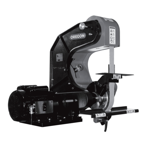
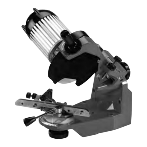
Oregon 88-102 User manual

1
#88-102 #88-103 Blade Sharpening Belt Grinder Meule à bande
d’affûtage de lame
Lijadora de banda de
afilador de cuchillas
INSTRUCTION MANUAL
For assembly, set up and operational use. 2 – 15
MODE D’EMPLOI
Pour le montage, le réglage et l’utilisation. 16 – 29
MANUAL DE INSTRUCCIONES
Para armado, instalación y uso operativo. 30 – 43
READ INSTRUCTIONS
THOROUGHLY BEFORE OPERATING
LIRE CES DIRECTIVES EN ENTIER
AVANT L’UTILISATION
LEA LAS INSTRUCCIONES CON ATENCIÓN
ANTES DE UTILIZAR EL DISPOSITIVO

2
Safety Requirements
OPERATOR, AND OPERATING AREA SAFETY
Serious injury or death may occur if minimum safety
precautions are not understood, and obeyed by
operators and those other persons who may be in
the immediate vicinity of the grinder. Persons who
operate or are in the immediate vicinity of the grinder
must be properly trained in, and use minimum safety
precautions and procedures for such machinery.
PERSONAL PROTECTION EQUIPMENT, SUCH AS
GRINDING GLOVES, HEARING PROTECTION, AND
SAFETY GLASSES MUST BE WORN WHEN USING THIS
EQUIPMENT. CHECK WITH YOUR COMPANY’S SAFETY
OFFICER FOR OTHER SAFETY REQUIREMENTS.
MINIMUM SAFETY REQUIREMENTS TO
OPERATE, OR WORK IN THE IMMEDIATE
VICINITY OF SUBJECT EQUIPMENT:
1. Read and understand all operating instructions,
manuals, labels, and other information
provided with the equipment.
2. Train operators and others in safe operating
practices. Post these instructions so they are
available for future reference and new operators.
3. Don’t expose the grinder to rain, or use the
grinder in damp or wet locations. Don’t use the
grinder if the power cord is damaged or wet.
4. Keep the work area well lit.
5. Do not use the grinder near ammable liquids or
gases. Sparks from the grinder can cause res.
6. Prevent body contact with grounded
surfaces, such as pipes or radiators.
7. Disconnect the power source when
the grinder is not in use.
8. Always keep electrical cords clear of rotating
parts and belts when in motion.
9. Electrical installation must be in accordance
with applicable codes and regulations.
10. Keep all visitors away from the grinder when
in use. Make sure visitors do not contact
the grinder or its electrical cord.
11. Do not wear loose clothing or jewelry. Non-skid
footwear is recommended when working with
the grinder. Wear protective hair coverings to
contain long hair. Wear proper safety equipment
and clothing to protect eyes, hands, face, arms,
legs, feet, and body from ying debris, forcibly
ejected work pieces and broken abrasive belts.
12. Use safety glasses. Everyday eyewear does
not have impact resistance lenses.
13. Wear a dust mask. Some of the dust created by
grinding activities may contain chemicals known to
cause cancer, birth defects or other harm. Provide
adequate ventilation. You may wish to install a
spark and debris arresting apparatus to contain
dust and debris, and to suppress sparks, further
limiting inhalation risk, and risk of re or explosion.
14. Keep all guards in place, properly
adjusted, and in working order.
15. Do not reach inside the safety guards
while the grinder is running.
16. Do not operate this grinder if the gap (nip point)
between a moving belt, wheel or disc, and the
work support surface exceeds 1/8" or 3.175 mm.
17. Never position the work rest table at an acute
angle between the top of the work rest table and
the moving belt or wheel. Doing so will create a
“nip point”that can cause serious injury should an
operator’s body part become entangled (pulled
into) the nip point created by this acute angle.
18. Do not operate this machine if the gap between the
moving abrasive belt, disc or wheel and the adjacent
face of the work rest (or table) will allow passage
of the work piece through the gap (nip point).
19. Note that certain alloys such as titanium may create
conditions where grinding debris can accumulate
in a tight gap creating a potential re hazard.
Failure to heed this warning may cause serious
bodily harm to the operator and/or bystanders.
When in doubt, consult with your safety ocer.
20. NEVER use this grinder if you are not properly
trained in its operations and safe use. If in
doubt, stop and ask for guidance.
21. Avoid contact with the belt. When running, the
abrasive belt is an aggressive cutting tool.
22. Always hold the work piece rmly and wear gloves
when grinding and apply steady pressure. Use
work piece holding devices whenever possible
to diminish the possibility that person will
come in contact with moving machine pieces,
or spark/debris output from the grinder.
23. Bolt the machine to a structurally sound
surface or pedestal. If a pedestal is used,
bolt the pedestal securely to the oor.
24. Before servicing, disconnect the grinder form the
power source. Never leave the grinder running
unattended. Turn the power o, and don’t leave
until the grinder comes to a complete stop.
25. Do not use damaged belts. Belts that
show wear should be discarded.
3
Safety Requirements
26. Avoid using directional belts. Using belts with a
butt joint will outperform belts that have a lap
joint and do not require directional installation.
Lap joint belts are also prone to separation.
27. Use abrasive belts from respected belt manufacturers.
Not all abrasive belts are created equal. Belts that are
very inexpensive are usually manufactured cheaply.
Contact your OREGON® dealer for quality replacement
parts. Be sure to use the right size abrasive belts.
28. Know what you’re grinding; avoid mixing
dierent metals, alloys and materials. Mixing
materials can crate a re or explosion hazard.
Exotic materials such as titanium, magnesium
and other chemically active materials have re
and explosion hazards that if ignored can result in
grave personal injury and/or property damage.
29. Ensure contact wheels and idler wheels are in good
condition and free from cuts or splits. If damaged
parts are found, immediately discontinue use
of the grinder and order replacement parts.
30. The use of stone or vitreous wheels on any OREGON
belt grinder is prohibited. The grinder guarding
is not suitable for these types of wheels.
31. Do not use this equipment when tired, ill or
under the inuence of alcohol or other drugs.
ROTATIONAL SPEED WARNING,
CONTACT WHEELS
Scope: Contact wheels manufactured by OREGON, which
have rubber or urethane tires. Examples include but are
not limited to stock codes 202, 302, 402, 502,702, 802, 902,
1002, 1202 and variants. Variants have stock codes that
begin with the base number; i.e. 802-S-55 is an 802 variant.
Users are warned not to exceed the below listed
revolutions per minute (RPM) on the subject wheels.
Failure to heed this warning may lead to tire de-bonding,
fragmentation, or other mechanical failure. Such
failures may cause serious personal injury to operators
or bystanders, and/or cause property damage.
STOCK CODE MAXIMUM RPM
202, 302 10,000
402, 502, 702 802 4,400
902, 1002 3,000
1202 2,200
OCCUPATIONAL NOISE EXPOSURE
OREGON products produce levels of noise consistent with
their intended purposes. The level and spectral content
of noise produced is dependent on the product type, the
degree that the product is maintained in proper operating
condition, the abrasive/media and accessories used, the
specic application, and the surrounding environment.
Noise levels produced by various OREGON grinders, as
measured at the factory, range from 80 to 93 decibels.
Product operators and persons in the immediate
product vicinity should be protected from excessive
noise does levels as prescribed in OSHA regulation 29,
piece 1910.95 titled“Occupational Noise Exposure”.
WARNING:
ROTATING EQUIPMENT CAN BE DANGEROUS
TO OPERATORS AND THOSE WHO MAY BE IN
ITS IMMEDIATE OPERATING VICINITY. IT IS THE
ABSOLUTE AND DIRECT RESPONSIBILITY OF
PURCHASERS, MANAGERS, AND OPERATORS
OF THIS EQUIPMENT TO UNDERSTAND
AND OBEY THE FOREGOING MINIMUM
OPERATING SAFETY REQUIREMENTS.
OREGON disclaims any and all responsibility for
injuries, damage, loss of income, or other adverse
consequence as might be incurred by purchasers,
managers, and operators of this equipment.
If you have questions or safety concerns regarding
operating the subject equipment please call your
authorized OREGON distributor, or Oregon Outdoor
Equipment Parts, OREGON, Blount, Inc., P.O. Box 22127,
Portland, Oregon 97222, 800-223-5168, or you can contact

4
Before Use
The model X400 belt grinder is a two wheel path belt
grinder that uses a 1-1/2-inch x 48-inch continuous
loop abrasive belt. For maximum eciency and your
safety we recommend you read and understand all
operating instructions, manuals, labels, and other
information provided with the equipment.
WARNING:
USE CAUTION WHEN LIFTING GRINDER. USE TWO
PEOPLE WHEN REMOVING FROM SHIPPING BOX.
Prior to operating the model X400 please
take time to do the following:
1. Ensure that you have received all of the items that
you ordered. Compare the packing slip with your
purchase order and with the physical items received.
2. Verify that there is no obvious shipping damage.
If shipping damage is discovered, notify
the freight carrier of your intention to le a
freight damage claim. They will assist you.
3. Verify that the AC power that is identied on
the machine as received matches the AC power
with which you intend to operate the machine.
Do not modify the machine’s wiring without
rst contacting your OREGON® distributor.
4. Do not modify or defeat any electrical
wiring safety feature. NEVER remove the
grounding pin on the AC electrical plug.
5. Verify that you have received an
Instructional Manual.
6. Verify that the safety guards for the machine
are in place and functional. See the schematic
on the previous page for part numbers.
7. Verify that the Contact Wheel Guard (Item 3,
pg. 5) and Vertical Platen (Item 9, pg. 5)
are mounted and adjusted such that the platen
lightly touches the back of the abrasive belt.
8. Prior to operating the model X400 read the
Instruction Manual carefully. Ensure that all persons
who will operate the machine or who will work
in the vicinity of the machine, read, understand,
and comply with these safety instructions.
9. Ensure that the grinder is located in an area that
provides operators with clear and unobstructed
access to the machine. The work place should
be free from oor obstructions, trip points, and
other faults that could reduce operator safety.
10. Bolt the machine to a structurally sound
surface or pedestal. If a pedestal is used,
bolt the pedestal securely to the oor.
11. Ensure that your AC electrical power source is
properly sized and properly fused for the machine you
purchased. Consult with a competent electrician to
determine the proper specications for your electrical
service prior to connecting your model belt grinder.

5
Product Description
AVAILABLEPARTS
Please refer to the parts drawing when ordering
parts. Not all components of the Grinder are
replacement items, but are illustrated as a convenient
reference for location. When ordering parts, give
Model number, serial number and description.
Call or write for current pricing:
Oregon Outdoor Equipment Parts, OREGON®,
Blount, Inc., P.O. Box 22127, Portland, Oregon
97222, 800-223-5168, or you can contact us by email at
1
9
8
3
12
10
11
4
5
6
7
2
ITEM PART NO. DESCRIPTION
88-109 Abrasive Belt, 1-1/2" x 48", 36 g
88-110 Abrasive Belt, 1-1/2" x 48", 120 g
011D On/O Switch
703-4 Contact Wheel Guard
728 V-Belt Guard
242-1 Safety Guard
015 AC Power Cord
1055 Tensioning Handle
246 Tracking Adjustment Knob
704-1A Vertical Platen
9609 Mower Blade Attachment
1203 Attachment Locking Lever
702-S-90 Contact Wheel
1
678912 13 15
10 11 14 16 17 18 19 20
4
3
25
1678912 13 15
10 11 14 16 17 18 19 20
4
3
2
5
1678912 13 15
10 11 14 16 17 18 19 20
4
3
25
1678912 13 15
10 11 14 16 17 18 19 20
4
3
25
1678912 13 15
10 11 14 16 17 18 19 20
4
3
2
5
1
6
78912 13 15
10 11 14 16 17 18 19 20
4
3
25
16
7
8912 13 15
10 11 14 16 17 18 19 20
4
3
25
167
8
912 13 15
10 11 14 16 17 18 19 20
4
3
25
1678
9
12 13 15
10 11 14 16 17 18 19 20
4
3
25
1678912 13 15
10
11 14 16 17 18 19 20
4
3
25
1678912 13 15
10
11
14 16 17 18 19 20
4
3
25
16789
12
13 15
10 11 14 16 17 18 19 20
4
3
25

6
Operation
PERFORM THE FOLLOWING STEPS
BEFORE EACHUSE OF YOUR
MODEL X400 BELT GRINDER:
1. Ensure that the gap (nip point) between the face of
the abrasive belt and work rest is adjusted so that your
work piece will not pass through this gap. (Figure 1)
2. Locate the 5/16" Allen screw that secures the table
support arm to the frame and loosen it. (Figure 2)
3. Adjust the mower blade table rest by loosening the
Attachment Locking Lever (Item 11, page 5) and
raise or lower the table to reduce the gap between
the belt and the table so the belt is NOT in contact
with the table. Tighten lever to secure table in place.
ADJUSTING VERTICAL/
HORIZONTALPOSITION
4. Next, loosen the contact wheel guard bolt with a 3/16"
Allen wrench. The machine can then be adjusted to
positions between vertical to horizontal, (Figure 5)
pivoting the machine and tightening. Take precautions
to not over tightening the Allen screws. As a rule of
thumb, a 1/4 turn past snug will suce. (Figure 2)
5. Check the nut that secures the contact wheel to its
mount. Ensure this nut is tightened to 10 to 15 foot
pounds of torque. (1.4 – 2 kg meters) (Figure 3)
6. To install or remove abrasive belt, push the Tension
Handle toward the rear of the machine. (Figure 4)
When the spring tension is released, open the door
of the guard and install or remove the abrasive
belt. Return the tension handle to its position at
the front of the machine to tighten the belt.
7. Hand turn the contact wheel in the direction of the
belt travel to align the belt. Close guard door. See the
tracking section (next) to learn how to track the belt.
8. When selecting where to grind on your machine,
remember that the X400 has three designated
grinding areas. The contact wheel, slack belt area,
and the platen area. You may wish to create a
larger slack belt area by removing the backup
platen. Remove the two Allen screws that secure
the platen to the contact wheel guard. Rotate the
guard forward to cover the pinch point between.
9. Ensure that your hands and other body parts
and electrical cords are completely clear of
the grinding belt, and pinch points.
10. Protect your face, eyes, and other body
tissue from the grinding debris.
WARNING:
FAILURE TO PROPERLY ADJUST THE NIP POINT
MAY CAUSE YOUR PART TO BECOME LODGED
OR EJECTED, AND MAY LEAD TO BODILY HARM.
WEAR PROPER CLOTHING AND PERSONAL PROTECTION
EQUIPMENT WHEN OPERATING.
3
45
6
1
2
ABRASIVE BELT
WORK REST
TABLE SUPPORT ARM ALLEN SCREW
CONTACT WHEEL GUARD BOLT
CONTACT WHEEL NUT
TENSIONING HANDLE
1
678912 13 15
10 11 14 16 17 18 19 20
4
3
25
1678912 13 15
10 11 14 16 17 18 19 20
4
3
2
5
1678912 13 15
10 11 14 16 17 18 19 20
4
3
25
1678912 13 15
10 11 14 16 17 18 19 20
4
3
25
1678912 13 15
10 11 14 16 17 18 19 20
4
3
2
5
1
6
78912 13 15
10 11 14 16 17 18 19 20
4
3
25
FIGURE 1 FIGURE 2 FIGURE 3 FIGURE 4
FIGURE 5

7
Lawn Mower Blade Sharpener Attachment
BEFORE OPERATING ANY EQUIPMENT PLEASE
READ AND REVIEW ALL SAFETY INSTRUCTIONS
FOR THE OREGON® MODEL X400.
PERSONAL PROTECTION EQUIPMENT, SUCH AS
GRINDING GLOVES, HEARING PROTECTION, AND
SAFETY GLASSES MUST BE WORN WHEN USING THIS
EQUIPMENT. CHECK WITH YOUR COMPANY’S SAFETY
OFFICER FOR OTHER SAFETY REQUIREMENTS.
MOUNTING
Your machine has been assembled and passed
numerous quality checks prior to shipping. The
mower blade attachment is fully assembled.
1. Using a 5/16" Allen wrench, loosen the
bolt that clamps down the main support
frame of the machine (See Figure 2).
2. Pivot machine into vertical position (Figure 6).
3. Tighten up the 5/16" bolt for the main
support frame of machine.
4. Open wheel cover door and rotate table
support arm to the down position.
5. Using a 7/16" wrench and a 5/32" Allen
wrench, remove bolt and attach the support
bar to the Table Support Arm (Figure 7).
6. Using a 3/16" Allen wrench, tighten
table support arm bolt.
7. Using a 3/16" Allen wrench, remove two screws from
the table support arm mounting block and attach
mower blade support table and tighten securely,
making sure to place the washer on the outside of the
bracket on the mower blade support table (Figure 7).
8. Remove nut and washer from drive shaft and attach
the contact wheel with the washer and nut using a
15/16" socket wrench. It will be a tight t, so proceed
carefully and use a little lubricating oil if needed.
INSTALLING THE BELT
9. Install belt over both wheels; lower the idler wheel by
pushing the tensioning handle to the vertical position.
10. Tension the belt by pulling the
tensioning handle towards you.
11. Adjust vertical platen with a 3/16" Allen wrench
so that the belt is gently touching the platen.
12. Close the safety guard door.
13. Plug machine in and turn machine on.
14. Check to see the belt is tracking in the middle of the
contact wheel. Adjust if needed by pushing/pulling
the tension release lever. If any abnormal vibrations
are noted, discontinue its use and review the
troubleshooting instructions on page 8. As always,
you may contact OREGON® for additional assistance.
ADJUSTING THE ATTACHMENT
Unlike a stone grinder, the diameter of the contact
wheel will remain nearly the same the entire life of the
wheel. Also, since the diameter of the wheel will remain
constant you will rarely need to adjust the table height.
Another advantage of using a belt to grind metal versus
a stone is when a stone reduces in diameter, you lose
surface speed, making grinding times increase. A stone
wheel may turn at 6,000 surface feet per minute when
it’s brand new, but after limited use the diameter of
the stone will decrease and the result will be increased
sharpening times and the stone will retain more heat.
2
1
43
5
FIGURE 6 FIGURE 7
CONTACT WHEEL
CONTACT WHEEL NUT
TABLE SUPPORT BAR
TABLE SUPPORT ARM
MOUNTING BLOCK
MOWER SUPPORT TABLE
1
678912 13 15
10 11 14 16 17 18 19 20
4
3
25
1678912 13 15
10 11 14 16 17 18 19 20
4
3
2
5
1678912 13 15
10 11 14 16 17 18 19 20
4
3
25
1678912 13 15
10 11 14 16 17 18 19 20
4
3
25
1678912 13 15
10 11 14 16 17 18 19 20
4
3
2
5

8
Operation
TRACKING THE BELT
1. Engage the motor by placing the Start/Stop switch
to Start. The belt must rotate smoothly in a
counter-clockwise direction around the machine
wheel belt path. If either of these conditions are
not met, immediately turn the machine OFF.
2. If the abrasive belt does not remain centered on the
contact wheel while the belt is moving,
(Figure 8A, B & C) use the tracking adjustment
knob on the upper left side of the machine
to track the belt to the center of the contact
wheel. Turning the knob will cause the belt to
track to the right or to the left. (Figure 9)
3. If the belt runs in reverse, (up from the oor, or
clockwise) correct this by changing the main
drive motor rotation direction. (See warning
section below for detailed instructions.)
4. If the abrasive belt tensions and tracks properly,
but the machine has excessive vibration, turn the
machine o and call OREGON® for assistance.
WARNING:
FIRST DISCONNECT THE MACHINE FROM ITS
AC POWER SOURCE. A COMPETENT ELECTRICIAN
SHOULD PERFORM ALL ELECTRICAL WORK ON
THE MODEL X400.
1. Reverse the motor direction of a three-phase motor by
reversing any two legs of the input power lines.
2. Reverse the motor direction of a xed speed single
phase motor by reversing leads 5 and 8 found within
the metal wiring box located on the motor, or as
otherwise instructed on the actual motor label.
1
FIGURE 8A, B& C FIGURE 9
Correct tracking Tracking left Tracking right
TRACKING ADJUSTMENT KNOB
1
678912 13 15
10 11 14 16 17 18 19 20
4
3
25

9
Operation
MAINTENANCE
•Every thirty days apply light machine oil to the tracking
assembly. (Figure 10) Two drops of oil are sucient.
•Every thirty days check the drive belt tensions. If you
can hear the belt“slap”the frame when the drive
motor starts, the belt may require re-tensioning.
•Re-tension by loosening the four bolts that
secure the motor to the base (Figure 11A & B)
and slide the motor backward. Do not over
tighten the belt. Doing so will shorten the life of
the machine bearings. Tighten the four bolts.
•Routinely inspect the machine for
loose hardware. Tighten as required.
•Vacuum daily or otherwise remove dust and debris
build-up from the machine and the machine belt track.
•Verify proper tracking of the belt by rotating the
tracking adjustment knob. (Figure 9, pg. 8)
If the belt does not track while the machine is
running it may be that the bolt that holds pressure
against the tracking knob (Figure 12) is loose.
•Using a 5/16" Allen wrench and a 9/16"
wrench, adjust the amount of pressure.
•Conversely, if the tracking adjustment
is too sti, loosen the bolt.
•If excess grinding dust has accumulated it may
be necessary to remove the tracking knob and
clean the shaft and the aluminum housing.
Reassemble using graphite or light machine oil.
•There are no other maintenance actions
required. All bearings are sealed for life
and require no additional lubrication.
1
2
3
4
5
FIGURE 10 FIGURE 11A & B FIGURE 12
TRACKING ASSEMBLY
FRONT MOTOR BOLTS
BACK MOTOR BOLTS
BOLT
TRACKING KNOB
1
678912 13 15
10 11 14 16 17 18 19 20
4
3
25
1678912 13 15
10 11 14 16 17 18 19 20
4
3
2
5
1678912 13 15
10 11 14 16 17 18 19 20
4
3
25
1678912 13 15
10 11 14 16 17 18 19 20
4
3
25
1678912 13 15
10 11 14 16 17 18 19 20
4
3
2
5

10
Replacement Parts
AVAILABLEPARTS
Please refer to the parts drawing when ordering
parts. Not all components of the attachments are
replacement items, but are illustrated as a convenient
reference of location and position in the assembly
sequence. When ordering parts, provide grinder model
number, part number and description of part.
Call or write for current pricing:
Oregon Outdoor Equipment Parts, OREGON®,
Blount, Inc., P.O. Box 22127, Portland, Oregon
97222, 800-223-5168, or you can contact us by email at
ITEM # PART # DESCRIPTION
9602 Angle Tube
9605 Alignment Plate
9606 Guide Block
9607 Workrest Support Arm
9608 Platen Bracket
9609 Work Table
9610 Arm Bracket
9611 Block Bracket
1203 Attachment Locking Lever
51/4" Washer
31 Screw, 1/4"-20 x 1-1/4"
9Button Head Black Oxide Screw,
10-24x1/2"
6 Flathead Screw, 1/4"-20x1-1/2"
4-0013 Kep Nut, 1/4"-20
209 Allen Head Screw, 1/4"-20 x 3/4"
711B Plated Shaft, 5/16"-18 x 3-3/8"
5-0046 Flathead Screw, 1/4"-20 x 1-3/4"
2-0014 Button Head Black Oxide Screw,
1/4"-28 x 1/2"
4-0009 Plated Jam Nut, 3/8"-16
1
678912 13 15
10 11 14 16 17 18 19 20
4
3
25
1678912 13 15
10 11 14 16 17 18 19 20
4
3
2
5
1678912 13 15
10 11 14 16 17 18 19 20
4
3
25
1678912 13 15
10 11 14 16 17 18 19 20
4
3
25
1678912 13 15
10 11 14 16 17 18 19 20
4
3
2
5
1
6
78912 13 15
10 11 14 16 17 18 19 20
4
3
25
16
7
8912 13 15
10 11 14 16 17 18 19 20
4
3
25
167
8
912 13 15
10 11 14 16 17 18 19 20
4
3
25
1678
9
12 13 15
10 11 14 16 17 18 19 20
4
3
25
1678912 13 15
10
11 14 16 17 18 19 20
4
3
25
1678912 13 15
10
11
14 16 17 18 19 20
4
3
25
16789
12
13 15
10 11 14 16 17 18 19 20
4
3
25
1678912
13
15
10 11 14 16 17 18 19 20
4
3
25
1678912 13 15
10 11
14
16 17 18 19 20
4
3
25
1678912 13
15
10 11 14 16 17 18 19 20
4
3
25
1678912 13 15
10 11 14
16
17 18 19 20
4
3
25
1678912 13 15
10 11 14 16
17
18 19 20
4
3
25
1678912 13 15
10 11 14 16 17
18
19 20
4
3
25
1678912 13 15
10 11 14 16 17 18
19
20
4
3
25
MODEL X400
MOWER BLADE
ATTACHMENT
1
2
3
16
4
17
18
11
18
12
5
9
6
10
15
7
13
19 8
14
14
14

11
Replacement Parts
ITEM # PART # DESCRIPTION
9603 Chain Saw Bar Grinding Platen
9604 Aluminum Block
9613 Platen Bracket
6-0001 Roll Plated Pin, 3/16" x 1"
6 Flathead Screw, 1/4"-20 x 1-1/2"
13 Cap Head Allen Screw
10-24 x 3/4"
5-0049 High Collar Lock Washer, #10
4-0013 Kep Nut, 1/4"-20
1
678912 13 15
10 11 14 16 17 18 19 20
4
3
25
1678912 13 15
10 11 14 16 17 18 19 20
4
3
2
5
1678912 13 15
10 11 14 16 17 18 19 20
4
3
25
1678912 13 15
10 11 14 16 17 18 19 20
4
3
25
1678912 13 15
10 11 14 16 17 18 19 20
4
3
2
5
1
6
78912 13 15
10 11 14 16 17 18 19 20
4
3
25
16
7
8912 13 15
10 11 14 16 17 18 19 20
4
3
25
167
8
912 13 15
10 11 14 16 17 18 19 20
4
3
25
1
3
4
7
8
5
6
2
PART # 88116
CHAIN SAW BAR GRINDING
ATTACHMENT (available as an
optional accessory)

12
Lawn Mower Blade Sharpening
WARNING:
If a belt is damaged or shows excessive wear,
immediately stop use of the belt and discard it.
SHARPENING
Mower blades
Free the blade of any grease, dirt,
or clippings prior to sharpening.
Check the blades to make sure
they are not bent or cracked.
Using a blade balancer, check the blade for its balance. When
sharpening start by grinding the light end of the blade and
then follow with the heavy end.
Move the blade in one direction only. Assuming that
you have a standard mower blade, your direction
would be from left to right. Rest blade on table, gently
move blade into rotating wheel and draw the blade to
the right. Multiple passes are required to achieve the
edge desired. Minimal pressure to the contact wheel is
recommended. The idea is to have the belt do the cutting,
not by using force against the contact wheel. Make
rapid passes, each pass should only take seconds in total
time. If you are not moving the blade across the wheel
in a rapid fashion, you will create hot spots in the blade,
and the blade will not move easily across the wheel.
After sharpening the rst edge, use the slack area
of the belt to remove any burrs that may have been
created in the sharpening procedure. Next, move to
the second edge and repeat the procedure. Check the
balance of the blade to ensure proper stock removal.
Mulching blade sharpening
Remove the vertical platen by
removing the two Allen bolts
that attach it to the contact
wheel guard. It is important to
readjust the contact wheel guard to remove the pinch point
created by removing the platen. By removing the platen you
create a large“slack”free belt area. By using a exible back
belt (J weight) or a narrow sti back belt you will be able to
use the slack area to sharpen the blade. The operator will
freehand the desired angle. After sharpening the rst edge,
use the slack area of the belt to remove any burrs that may
have been created in the sharpening procedure. Next, move
to the second edge and repeat the procedure. Check the
balance of the blade to ensure proper stock removal.
Rotary-style oset ail blade sharpening
Free the blade of any foreign
substances. Depending on style
of the blade, balancing the blade
maybe dierent than described in this manual. Most rotary
blades can be balanced using a simple balance-style scale.
Since there is no other way to check for balance due to the
oset hole style of the blades, use of a scale is to make sure
that the blades are all equal in mass. Using a scale allows you
to make sure each blade weighs the same amount, keeping
the blades in balance.
You may also choose to check the blades using a standard
scale. Once again, start with the lightest blade and then
sharpen the heavier blade, checking the blades for balance.
Attach the galvanized tubing (Item 1, page 10) to the
worktable, using two button head black oxide screws
(Item 18, page 10) and two kep nuts (Item 14, page 10).
This changes the angle for the rotary-style blade to a
factory recommended angle. As with mower blades, it is
recommended to move the blade in one direction only.
If the blade has deep chips, use the contact wheel to
“face the blade.” Move up on the contact wheel a couple
of inches to the centerline and run the blade back and
forth several times to even the edge of the blade. Next
you will rest the blade against the tubing and start the
sharpening process. Again, use only light inward pressure.
The belt and speed of the belt will do all the work for you.
Chipper blade sharpening
Free the blade of any foreign
substances. Depending on style
of the blade, balancing the blade
maybe dierent than described
in this manual. Most chippers require all blades to be the
same height. Start with the shortest blade and use it for a
reference, then move on to the others in the set.
Only sharpen blades that are long and wide enough to safely
hold on to. As with any sharpening process on the grinder
move only in one direction and apply minimal inward force.
GRINDING BELTS
OREGON® recommends using only a 3M or Norton 24
or 36 grit ceramic belts to sharpen blades using the
blade attachment. (3M 987FI or Norton Blaze R980.)
These belts contain cooling aids and are constructed
for heavy stock removal. Replacement belts can
be ordered from your OREGON distributor.
Remove any burrs on the back of the blade by
making a couple of passes on the slack portion
of the belt. This will reduce the eort required
when moving the blade across the table.

13
Warranties
THE OREGON® CUSTOMERSATISFACTION
POLICY LIMITEDWARRANTY
OREGON® | Blount, Inc. warrants its products to be free
from defects in materials and workmanship for as long
as they are owned by the original retail purchaser.
If you like our products, please tell your friends. If you are
not satised with our products, for any reason, please
tell us. OREGON wants to provide you with products
that perform to your full satisfaction. We welcome
you to contact us as shown in the last paragraph.
LIABILITY UNDER THIS WARRANTY IS LIMITED TO
REPLACEMENT PARTS, AT THE OPTION OF YOUR OREGON®
DISTRIBUTOR AND OREGON. PLEASE CONTACT YOUR
OREGON DISTRIBUTOR OR US DIRECTLY. OREGON
PRODUCTS ARE NOT WARRANTED AGAINST NORMAL WEAR
AND TEAR, USER ABUSE, IMPROPER MAINTENANCE OR
IMPROPER REPAIR. REPLACEMENT OF DEFECTIVE PRODUCT
IS THE EXCLUSIVE REMEDY UNDER THIS WARRANTY AND
ANY APPLICABLE IMPLIED WARRANTY. THE REPLACEMENT
WILL BE UNDERTAKEN AS SOON AS REASONABLY POSSIBLE
AFTER RECEIPT OF THE DEFECTIVE PRODUCT. TO THE
EXTENT PERMITTED BY LAW, ANY IMPLIED WARRANTY
OF MERCHANTABILITY OR FITNESS FOR A PARTICULAR
PURPOSE APPLICABLE TO THIS PRODUCT IS LIMITED TO
THE DURATION AND SCOPE OF THIS EXPRESS WARRANTY.
OREGON SHALL NOT BE LIABLE FOR ANY CONSEQUENTIAL
OR INCIDENTAL DAMAGES. SOME STATES DO NOT ALLOW
LIMITATIONS ON HOW LONG AN IMPLIED WARRANTY LASTS
OR DO NOT ALLOW THE EXCLUSION OF CONSEQUENTIAL
DAMAGES, SO THE ABOVE LIMITATION OR EXCLUSION MAY
NOT APPLY TO YOU. THIS WARRANTY GIVES THE ORIGINAL
OWNER SPECIFIC LEGAL RIGHTS, AND YOU MAY ALSO
HAVE OTHER RIGHTS WHICH VARY FROM STATE TO STATE.
To contact us in the U.S.A. regarding OREGON Outdoor
Equipment Parts (lawnmower blades and replacement
parts for small engines, lawnmowers and many other
types of outdoor power equipment), we welcome your
calls between the hours of 7:30 a.m. and 4:30 p.m. (Pacic
Time), Monday through Friday at 800-223-5168, or you
can write to: Technical Services Department, Oregon
Outdoor Equipment Parts, OREGON, Blount, Inc., P.O. Box
22127, Portland, Oregon 97222, or you can contact us

14
Notes

15
Notes

16
Exigences de sécurité
SÉCURITÉ DE L’OPÉRATEUR ET
DE LA ZONE D’UTILISATION
De graves blessures et la mort peuvent survenir si un
minimum de précautions de sécurité ne sont pas comprises
et suivies par les opérateurs et les autres personnes se
trouvant dans la zone de la meule. Les personnes qui
utilisent ou qui se trouvent près de la meule doivent avoir
reçu une formation appropriée et appliquer des précautions
de sécurité et suivre les procédures pour la machinerie.
LES ÉQUIPEMENTS DE PROTECTION INDIVIDUELLES
TELS QUE DES GANTS D’AFFÛTAGE, DES DISPOSITIFS DE
PROTECTION POUR LES OREILLES ET DES LUNETTES DE
SÉCURITÉ DOIVENT ÊTRE PORTÉS LORS DE L’UTILISATION
DE CET ÉQUIPEMENT. INFORMEZVOUS AUPRÈS DE LA
PERSONNE RESPONSABLE DE LA SÉCURITÉ DE VOTRE
ENTREPRISE SUR LES AUTRES EXIGENCES DE SÉCURITÉ.
VOICI LES EXIGENCES DE SÉCURITÉ MINIMUM
POUR L’UTILISATION OU LE TRAVAIL À
PROXIMITÉ DE L’ÉQUIPEMENT :
1. Lire et s’assurer de comprendre toutes les directives
d’utilisation, les manuels, les étiquettes ainsi que les
autres renseignements fournis avec l’équipement.
2. Former les opérateurs et les autres personnes
concernées sur les pratiques d’utilisation
sécuritaires. Acher ces directives de sorte
qu’elles soient disponibles à des ns de référence
futures et pour les nouveaux opérateurs.
3. Ne pas exposer la meule à la pluie ni utiliser
la meule dans un endroit humide ou
mouillé. Ne pas utiliser la meule si le cordon
d’alimentation est endommagé ou mouillé.
4. Garder la zone de travail bien éclairée.
5. Ne pas utiliser la meule près de liquides ou de
gaz inammables. Des étincelles provenant de
la meule peuvent provoquer un incendie.
6. Éviter que le corps ne touche aux surfaces mises
à la terre tels que les tuyaux et les radiateurs.
7. Déconnecter la source d’alimentation
lorsque la meule n’est pas utilisée.
8. Garder toujours les cordons électriques à l’écart des
pièces rotatives et des bandes en mouvement.
9. L’installation électrique doit être conforme
aux codes et règlements applicables.
10. Garder les visiteurs éloignés de la meule lorsqu’elle
est utilisée. S’assurer que ces visiteurs ne touchent
pas à la meule ni à son cordon électrique.
11. Ne pas porter de vêtements amples ni de bijoux. Il est
recommandé de porter des chaussures antidérapantes
lors du travail avec la meule. Porter des dispositifs de
protection pour les cheveux qui peuvent contenir
les cheveux longs. Porter des équipements et des
vêtements de sécurité appropriés pour protéger les
yeux, les mains, le visage, les bras, les jambes, les pieds
et le corps contre les débris projetés, des morceaux
éjectés avec force et des bandes abrasives cassées.
12. Utiliser des lunettes de sécurité. Les
lunettes régulières ne sont pas dotées de
lentilles qui résistent aux impacts.
13. Porter un masque antipoussière. Une partie de la
poussière créée par les activités d’aûtage peut
contenir des produits chimiques reconnus comme
une cause de cancer, d’anomalies congénitales et
d’autres problèmes liés à la reproduction. Utiliser
dans un endroit bien aéré. Un dispositif d’arrêt
d’étincelles et de débris peut être installé pour
contenir la poussière et les débris et éliminer les
étincelles en limitant ainsi le risque d’inhalation ainsi
que le risque d’un incendie et d’une explosion.
14. Garder les gardes en place, correctement
ajustées et en bon état.
15. Ne pas passer les mains à travers les gardes de
sécurité lorsque la meule est en marche.
16. Ne pas utiliser cette meule si l’intervalle (point de
pincement) entre une bande, une meule ou un
disque et la surface de support excède 3,175 mm.
17. Ne placer jamais la table d’appui à un angle aigu entre
le haut de la table d’appui et la bande ou la meule en
mouvement. Cela entraînerait un point de pincement
qui peut provoquer des blessures graves si une partie
du corps de l’opérateur se faisait prendre (attiré)
dans le point de pincement créé par l’angle aigu.
18. Ne pas utiliser cette machine si l’intervalle
entre la bande, la meule ou le disque abrasif
et la surface adjacente à la surface d’appui
(ou la table) permet le passage de la pièce
par l’intervalle (point de pincement).
19. Prendre note que certains alliages tels que le titane
peuvent créer des conditions dans lesquelles les
débris de meulage s’accumulent dans un intervalle
restreint en créant un risque d’incendie. Manquer
de tenir compte de cet avertissement peut entraîner
des blessures graves à l’opérateur et aux personnes
environnantes. En cas de doute, s’informer auprès
de la personne responsable de la sécurité.
20. NE JAMAIS utiliser la meule si vous n’avez pas reçu
une formation appropriée sur son fonctionnement
et son usage sécuritaires. En cas de doute,
arrêter le travail et demander des conseils.
21. Éviter tout contact avec la bande.
Lorsqu’elle est en marche, la bande abrasive
est un puissant outil de coupe.

17
Exigences de sécurité
22. Tenir toujours fermement la pièce travaillée et
porter des gants lors de l’aûtage et appliquer une
pression constante. Utiliser des dispositifs de retenue
de pièces lorsque c’est possible an de réduire le
risque qu’une personne ne vienne en contact avec
des pièces mobiles de la machine ou des étincelles
et des débris en provenance de la machine.
23. Fixer fermement la machine à une surface de structure
solide ou à un socle. Lorsqu’un socle est utilisé, xer
fermement le socle au plancher à l’aide de boulons.
24. Avant l’entretien, débrancher la meule de sa
source d’alimentation. Ne pas laisser la machine
sans surveillance lorsqu’elle est en marche.
Couper l’alimentation et ne pas partir avant
que la meule ne soit complètement arrêtée.
25. Ne pas utiliser de boulons endommagés. Les bandes
présentant des dommages doivent être jetées.
26. Éviter d’utiliser des bandes directionnelles. L’utilisation
de bandes avec joint d’extrémité sont supérieures aux
bandes ayant un joint de chevauchement et n’exigent
pas une installation directionnelle. Les bandes ayant
un joint de chevauchement ont tendance à se séparer.
27. Utiliser des bandes abrasives fabriquées par des
fabricants reconnus. Les bandes abrasives ne
sont pas toutes fabriquées de la même façon.
Les courroies à très bas prix sont habituellement
fabriquées à moindre qualité. Communiquez avec
votre détaillant OREGON® pour vous procurer des
pièces de rechange de qualité. S’assurer d’utiliser
les bandes abrasives de la bonne dimension.
28. S’assurer de connaître les matériaux de la pièce
aûtée; éviter de mêler diérents métaux, alliages
et matériaux. Le mélange de ces matériaux peut
provoquer un risque d’incendie et d’explosion.
Des matériaux exotiques tels que le titane, le
magnésium et autres matériaux chimiquement
actifs présentent des risques d’incendie et
d’explosion qui, si ignorés, peuvent entraîner
des blessures graves et des dommages.
29. S’assurer que les roues de contacts et les
roues de tension sont en bon état et qu’elles
ne comportent pas de coupures ni de fentes.
Lorsque des pièces sont trouvées endommagées,
cesser immédiatement d’utiliser la meule et
commander des pièces de rechange.
30. Il est interdit d’utiliser des meules en pierre
ou en vitre sur toute meule à bande OREGON.
Les dispositifs de protection de meule ne
conviennent pas à ce type de meules.
31. L’opérateur ne doit pas utiliser cet équipement lorsqu’il
est fatigué ou sous l’inuence de l’alcool ou de drogue.
AVERTISSEMENT RELIÉ À LA VITESSE DE
ROTATION, ROUES DE CONTACT
Portée : Les roues de contact fabriquées par OREGON,
dotées de pneus en caoutchouc ou en uréthane. Par
exemple, les codes de stocks 202, 302, 402, 502,702,
802, 902, 1002, 1202 et les variantes. Les variantes ont
des codes de stock qui commencent par le numéro de
base, par exemple 802-S-55 est une variante 802.
Nous avertissons les utilisateurs de ne pas excéder
le nombre de tours par minute (tr/min) des meules.
Manquer de tenir compte de cet avertissement peut
entraîner un décollement, une fragmentation ou une
autre défaillance mécanique. Ces défaillances peuvent
entraîner des blessures graves à l’opérateur ou aux
personnes environnantes ainsi que des dommages.
CODE DE STOCK TR/MINMAXIMUM
202, 302 10 000
402, 502, 702 802 4 400
902, 1002 3 000
1202 2 200
EXPOSITION AUX BRUITS SUR
LE LIEU DU TRAVAIL
Les produits OREGON produisent des niveaux de bruit
correspondant à leurs utilisations prévues. Le niveau et le
contenu du spectre de bruit produit dépendent du type
de produit, du degré auquel le produit est gardé en bon
état d’utilisation, le type d’abrasif et les accessoires utilisés,
l’application spécique et le milieu environnant.
Les niveaux de bruits produits par diérentes meules
OREGON, tels que mesurés à l’usine s’échelonnent de 80 à 93
décibels. Les opérateurs de produit ainsi que les personnes
se trouvant à proximité doivent se protéger contre les
niveaux de bruits excessifs tel que prescrit dans le règlement
de l’OSHA 29, Partie 1910.95 intitulé Exposition aux bruits sur
le lieu du travail.
AVERTISSEMENT :
LES ÉQUIPEMENTS ROTATIFS PEUVENT
PRÉSENTER DES DANGERS POUR LES
OPÉRATEURS ET LES PERSONNES SE TROUVANT
À PROXIMITÉ. LES ACHETEURS, LES DIRECTEURS
ET LES OPÉRATEURS DE CET ÉQUIPEMENT ONT
LA RESPONSABILITÉ DIRECTE ET ABSOLUE DE
S’ASSURER DE BIEN COMPRENDRE ET DE SE
CONFORMER AUX EXIGENCES DE SÉCURITÉ
MINIMUM LORS DE L’UTILISATION.
OREGON se dégage de toute responsabilité
liée à des blessures, des dommages, des pertes
de revenus ou d’autres conséquences néfastes
pouvant toucher les acheteurs, les directeurs
et les opérateurs de cet équipement.
Si vous avez des questions ou des préoccupations reliées à la
sécurité de l’utilisation de l’équipement, veuillez téléphoner
à votre distributeur autorisé OREGON, ou à Technical Services
Department, Oregon Outdoor Equipment Parts, OREGON®,
Blount, Inc., P.O. Box 22127, Portland, Oregon 97222, au
800-223-5168 et vous pouvez aussi nous envoyer un courriel

18
Avant l’utilisation
La meule à bande de modèle X400 est une meule
à bande à deux roues d’acheminement qui utilise
une bande abrasive à boucle continue de 1-1/2 po
x 48 po. Pour obtenir un maximum d’ecacité et
assurer la sécurité, nous recommandons de lire et
de vous assurer de comprendre toutes les directives
d’utilisation, les manuels, les étiquettes ainsi que les
autres renseignements fournis avec l’équipement.
AVERTISSEMENT:
PRENDRE DES PRÉCAUTIONS LORS DU LEVAGE DE LA
MEULE. DEUX PERSONNES SONT REQUISES POUR LE
RETRAIT DE LA MACHINE DE LA BOÎTE D’EXPÉDITION.
Avant d’utiliser le modèle 400, veuillez prendre
le temps d’eectuer la procédure suivante :
1. S’assurer d’avoir reçu tous les articles
commandés. Comparer le bordereau de
marchandises à votre bon de commande et
vérier physiquement les articles reçus.
2. Vérier qu’il n’y a pas de dommage dû au transport. Si
des dommages sont survenus pendant le transport,
aviser le transporteur de votre intention de présenter
une réclamation pour les dommages dus au transport.
Le transporteur vous donnera de l’assistance.
3. Vérier que l’alimentation C.A., identiée
sur la machine comme reçue correspond à
l’alimentation C.A. qui sera utilisée pour faire
fonctionner la machine. Ne pas modier le
câblage de la machine sans avoir préalablement
communiqué avec le distributeur OREGON®.
4. Ne pas modier les caractéristiques de sécurité
du câblage électrique. Ne JAMAIS retirer la
broche de mise à la terre de la che C.A.
5. S’assurer d’avoir reçu un mode d’emploi.
6. Vérier si les gardes de sécurité sont en place et
en état de marche. Consulter le schéma de la page
précédente au sujet des numéros de pièces.
7. Vérier si la garde de la roue de contact (article 3,
p. 19) et que le plateau vertical (article 9, p. 19)
sont installés et ajustés de sorte que le plateau
touche légèrement l’endos de la bande abrasive.
8. Avant d’utiliser le modèle X400, prendre le temps
de lire attentivement le mode d’emploi. S’assurer
que toutes les personnes qui utiliseront la machine
ou qui travailleront à proximité de la machine lisent,
comprennent et se conforment à ces directives.
9. S’assurer que la meule est placée à un endroit
qui procure aux opérateurs un accès libre et
non obstrué à la machine. Le site de travail
doit être libre d’obstructions, de points de
trébuchement et d’autres éléments qui
pourraient réduire la sécurité de l’opérateur.
10. Fixer fermement la machine à une surface de structure
solide ou à un socle. Lorsqu’un socle est utilisé, xer
fermement le socle au plancher à l’aide de boulons.
11. S’assurer que la source d’alimentation C.A. est de
la bonne valeur nominale et comporte les fusibles
appropriés pour la machine achetée. Consulter
un électricien compétent pour déterminer si les
spécications du service électrique sont appropriées
avant de connecter le modèle de meule à bande.

19
Description du produit
PIÈCES DISPONIBLES
Veuillez vous référer aux schémas des pièces lors
de la passation de commande. Les composants de
la meule ne sont pas tous remplaçables, mais ils
sont tous illustrés à titre de référence pratique pour
déterminer leur emplacement. Lors de la passation
de la commande, veuillez indiquer le numéro de
modèle, le numéro de série ainsi que la description.
Veuillez téléphoner ou écrire pour connaître le prix :
Oregon Outdoor Equipment Parts, OREGON®,
Blount, Inc., P.O. Box 22127, Portland, Oregon 97222,
800-223-5168 et vous pouvez aussi nous envoyer un courriel
1
9
8
3
12
10
11
4
5
6
7
2
ARTICLE N DE PIÈCE DESCRIPTION
88-109 Bande abrasive, 1-1/2 po x 60 po 36 g
88-110 Bande abrasive, 1-1/2 po x 60 po 120 g
011D Interrupteur marche-arrêt
703-4 Garde de roue de contact
728 Garde de courroie en V
242-1 Garde de sécurité
015 Cordon d’alimentation C.A.
1055 Poignée de mise en tension
246 Bouton d’ajustement de positionnement
704-1A Plateau vertical
9609 Accessoire de lame de tondeuse
1203 Levier de verrouillage d’accessoire
702-S-90 Roue de contact
1
678912 13 15
10 11 14 16 17 18 19 20
4
3
25
1678912 13 15
10 11 14 16 17 18 19 20
4
3
2
5
1678912 13 15
10 11 14 16 17 18 19 20
4
3
25
1678912 13 15
10 11 14 16 17 18 19 20
4
3
25
1678912 13 15
10 11 14 16 17 18 19 20
4
3
2
5
1
6
78912 13 15
10 11 14 16 17 18 19 20
4
3
25
16
7
8912 13 15
10 11 14 16 17 18 19 20
4
3
25
167
8
912 13 15
10 11 14 16 17 18 19 20
4
3
25
1678
9
12 13 15
10 11 14 16 17 18 19 20
4
3
25
1678912 13 15
10
11 14 16 17 18 19 20
4
3
25
1678912 13 15
10
11
14 16 17 18 19 20
4
3
25
16789
12
13 15
10 11 14 16 17 18 19 20
4
3
25

20
Utilisation
EFFECTUER LES ÉTAPES SUIVANTES
AVANT CHAQUE UTILISATION DE LA
MEULE À BANDE DE MODÈLE X400 :
1. S’assurer que l’intervalle (point de pincement)
entre la face de la bande abrasive et l’appui de
travail est ajusté de sorte que la pièce travaillée
ne puisse pas passer dans l’intervalle. (Figure 1)
2. Trouver la vis Allen de 5/16 po qui xe le bras du
support de la table au châssis et la desserrer. (Figure 2)
3. Ajuster le support de la table de lames de tondeuse
en desserrant le levier de verrouillage de l’accessoire
(article 11, à la page 19) et soulever ou abaisser
la table an de réduire l’intervalle entre la bande et
la table de sorte que la bande NE touche PAS à la
table. Serrer le levier pour xer la table en place.
AJUSTEMENT DES POSITIONS
VERTICALE ET HORIZONTALE
4. Desserrer ensuite le boulon de garde de la roue
de contact à l’aide d’une clé Allen de 3/16 po. La
machine peut alors être ajustée aux positions se
trouvant entre la verticale et l’horizontale (Figure 5),
en faisant pivoter la machine et en serrant. Prendre
soin de ne pas serrer en excès les vis Allen. De
façon générale, eectuer ¼ de tour de plus lorsque
la vis commence à être serrée. (Figure 2)
5. Vérier si l’écrou xe solidement la roue de contact
à son montage. S’assurer que cet écrou est serré
à un couple de 1,4 – 2 kg-mètres. (Figure 3)
6. Pour installer ou retirer une bande abrasive,
pousser la poignée de mise en tension vers l’arrière
de la machine. (Figure 4) Lorsque la tension du
ressort est relâchée, ouvrir la porte de la garde
et installer ou retirer la bande abrasive. Replacer
la poignée de mise en tension à sa position à
l’avant de la machine pour serrer la bande.
7. Tourner à la main la roue de contact dans le
sens de déplacement de la bande pour aligner
la bande. Fermer la porte de la garde. Voir la
section suivante sur le positionnement (p. 22)
pour apprendre la façon de placer la bande.
8. Lors de la sélection de l’endroit à aûter sur la
machine, se souvenir que le modèle X400 est doté
de trois zones d’aûtage désignées. La roue de
contact, la zone lâche de la courroie et la zone du
plateau. Il est possible de créer une zone lâche de
courroie plus grande en retirant le plateau de réserve.
Enlever les deux vis Allen qui xent le plateau à la
garde de roue de contact. Tourner la garde vers
l’avant an de couvrir le point de pincement.
9. S’assurer que les mains et les autres parties du corps
ainsi que les cordons électriques soient éloignées de
la bande d’aûtage et des points de pincement.
10. Protéger le visage, les yeux et les autres
tissus corporels des débris d’aûtage.
AVERTISSEMENT :
LE MANQUEMENT À AJUSTER CORRECTEMENT
LE POINT DE PINCEMENT PEUT ENTRAÎNER UN
EMPRISONNEMENT OU UNE ÉJECTION DE LA
PIÈCE ET PROVOQUER DES BLESSURES.
PORTER DES VÊTEMENTS ET DE L’ÉQUIPEMENT DE
PROTECTION INDIVIDUELLE APPROPRIÉS LORS DE
L’UTILISATION DE LA MACHINE.
3
45
6
1
2
BANDE ABRASIVE
APPUI DE TRAVAIL
VIS ALLEN DE BRAS DE SUPPORT DE LA TABLE
BOULON DE GARDE DE ROUE DE CONTACT
ÉCROU DE ROUE DE CONTACT
POIGNÉE DE MISE EN TENSION
1
678912 13 15
10 11 14 16 17 18 19 20
4
3
25
1678912 13 15
10 11 14 16 17 18 19 20
4
3
2
5
1678912 13 15
10 11 14 16 17 18 19 20
4
3
25
1678912 13 15
10 11 14 16 17 18 19 20
4
3
25
1678912 13 15
10 11 14 16 17 18 19 20
4
3
2
5
1
6
78912 13 15
10 11 14 16 17 18 19 20
4
3
25
FIGURE 1 FIGURE 2 FIGURE 3 FIGURE 4
FIGURE 5
This manual suits for next models
1
Table of contents
Languages:
Other Oregon Grinder manuals

Oregon
Oregon 510A User manual

Oregon
Oregon 410-120 User guide

Oregon
Oregon 410-230 User manual

Oregon
Oregon 720-120 User guide

Oregon
Oregon 511AX User manual

Oregon
Oregon 710-120 User guide

Oregon
Oregon 510A User manual

Oregon
Oregon 730-120 User guide

Oregon
Oregon Mini Grinder User manual

Oregon
Oregon 310-120 User guide

Oregon
Oregon 590181 User manual

Oregon
Oregon 109179 User manual

Oregon
Oregon 109179 User manual

Oregon
Oregon 760 User manual

Oregon
Oregon 310-230 User guide

Oregon
Oregon Dura Max 511A Manual

Oregon
Oregon 530-120H User guide

Oregon
Oregon 88-025 User manual

Oregon
Oregon Dura Max 511A User manual

Oregon
Oregon 511AX User manual