Oregon 720-120 User guide

Original Instruction Manual
Auto Chain Grinder Model 720-120
OregonProducts.com
585124ab_Auto Chain Grinder_OM_720-120.indd 1 3/1/17 3:05 PM

720-120
2
Table of Contents
Table of Contents
1 Introduction . . . . . . . . . . . . . . . . 3
1.1 Important user information . . . . . . . . .3
1.2 About this manual . . . . . . . . . . . . . . 3
1.3 Intended use . . . . . . . . . . . . . . . . . 3
1.4 Nameplate . . . . . . . . . . . . . . . . . . 4
1.5 Recycling information . . . . . . . . . . . . 4
2 Safety . . . . . . . . . . . . . . . . . . . 5
2.1 Explanation of warning levels. . . . . . . .5
2.2 General machine safety warnings . . . . . 5
2.3 Signs and symbols . . . . . . . . . . . . . .7
3 Product Description. . . . . . . . . . . . 8
3.1 Product overview. . . . . . . . . . . . . . .8
3.2 Front view. . . . . . . . . . . . . . . . . . .9
3.3 Back view . . . . . . . . . . . . . . . . . . 10
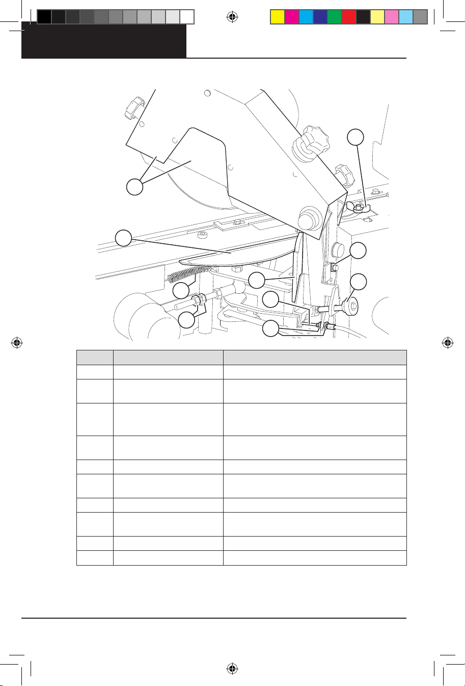
3.4 Grinding head . . . . . . . . . . . . . . . 11
3.5 Pneumatic chain tensioner . . . . . . . . 12
3.6 Controls . . . . . . . . . . . . . . . . . . . 13
3.6.1 Counter . . . . . . . . . . . . . . . . 14
3.6.2 Grinding speed knob . . . . . . . . 14
3.7 Chain overview . . . . . . . . . . . . . . . 14
3.8 Technical data . . . . . . . . . . . . . . . 15
4 Installation. . . . . . . . . . . . . . . . 16
4.1 Safety during installation . . . . . . . . . 16
4.2 Site requirements . . . . . . . . . . . . . 16
4.3 Unpacking the machine . . . . . . . . . . 16
4.4 Assembling the stand . . . . . . . . . . . 17
4.5 Assembling the pneumatic
chain tensioner . . . . . . . . . . . . . . . 19
4.6 Bench-mounting the machine . . . . . . 21
4.7 Installing the grinding wheel . . . . . . . 22
4.8 Testing the machine before first use . . .23
© Blount, Inc. Pricing and specifications subject to change without notice. All rights reserved.
Oregon® is a trademark of Blount, Inc. in the United States and/or in other countries.
5 Operation . . . . . . . . . . . . . . . . 24
5.1 Safety during operation . . . . . . . . . . 24
5.2 Preparing for operation . . . . . . . . . . 24
5.2.1 Preparing the grinding wheel. . . . 24
5.2.2 Setting the head-tilt angle . . . . . 25
5.2.3 Setting the top-plate angle . . . . . 26
5.2.4 Inserting the chain . . . . . . . . . . 26
5.2.5 Making the grinding settings . . . . 29
5.2.6 Using skip tooth mode . . . . . . . 32
5.3 Operating the machine. . . . . . . . . . .33
6 Maintenance and Service. . . . . . . . 36
6.1 Safety during maintenance . . . . . . . . 36
6.2 Frequency of maintenance . . . . . . . . 36
6.3 Changing the grinding wheel and
fitting the grinding wheel guard . . . . . 37
6.4 Setting the depth gauge height . . . . . . 38
6.5 Adjusting the chain lock . . . . . . . . . . 38
6.6 Checking and adjusting the wire . . . . . 39
6.7 Service . . . . . . . . . . . . . . . . . . . 41
7 Troubleshooting. . . . . . . . . . . . . 42
7.1 Troubleshooting procedure . . . . . . . . 42
7.2 Sharpening test . . . . . . . . . . . . . . 42
7.3 Issues . . . . . . . . . . . . . . . . . . . . 43
7.4 Troubleshooting indicators . . . . . . . . 44
8 Accessories and Spare Parts . . . . . 45
8.1 Ordering information . . . . . . . . . . . 45
8.2 List of accessories . . . . . . . . . . . . .45
8.3 Converter . . . . . . . . . . . . . . . . . . 50
9 Grinding Angles Chart . . . . . . . . . 52
10 Warranty and Service. . . . . . . . . . 54
585124ab_Auto Chain Grinder_OM_720-120.indd 2 3/1/17 3:05 PM

720-120
3
1 Introduction
1 Introduction
1.1 Important user information
WARNING Before you install, operate or perform maintenance on this machine, you must read the
safety information in this manual. Obey the instructions in this manual to prevent injuries or damage to the
equipment.
1.2 About this manual
This user manual describes how to safely install, operate, and perform basic maintenance on the
Oregon 720-120 Auto Chain Grinder chain sharpening machine. This manual also describes the parts of
the machine, and it shows different accessories and spare parts that are available.
1.3 Intended use
The machine must only be used to sharpen the cutting chains used on power saws, forestry machines and
harvesters. It automatically sharpens the cutting teeth, gullets, and depth gauges on chains. The machine
is designed for indoor use only.
Unintended use
The machine must not be used outdoors or in a manner that is not described in this manual.
585124ab_Auto Chain Grinder_OM_720-120.indd 3 3/1/17 3:05 PM

720-120
4
1 Introduction
1.4 Nameplate
This nameplate is placed on the Oregon 720-120 Auto Chain Grinder’s grinding head.
1.5 Recycling information
This symbol shows that electrical and electronic equipment must not be disposed of as
unsorted municipal waste. It must be collected separately. Recycle according to current local
rules and regulations.
Model: 720-120
Mfg: 2016-43 Weight: 17.5kg
Input: 12V DC 12A, no: 3250min-1
Grinding wheel suitable for 3500min-1
Arbor: Ø .630 In (16mm)
Certified to CAN/CSA-C22.2 No. 62841-1:15
Conforms to UL62841-1
S/N: 12345 Made in Sweden
5005667
585124ab_Auto Chain Grinder_OM_720-120.indd 4 3/1/17 3:05 PM

720-120
5
2 Safety
2 Safety
2.1 Explanation of warning levels
This section contains safety information for the Oregon 720-120 Auto Chain Grinder. This manual contains
WARNINGS, CAUTIONS, and NOTES that are applicable for the safe operation of the machine.
DANGER Indicates a hazard with a high level of risk which, if not avoided, will result in death or
serious injury.
WARNING Indicates a hazard with a medium level of risk which, if not avoided, could result in death
or serious injury.
CAUTION Indicates a hazard with a low level of risk which, if not avoided, could result in minor or
moderate injury.
IMPORTANT Indicates a potential situation exists which, if not avoided, may result in damage to your
grinder or property.
2.2 General machine safety warnings
WARNING Read all safety warnings, instructions, illustrations, and specifications provided with this
machine. Failure to follow all instructions listed below may result in electric shock, fire, and/or serious
injury. Save all warnings and instructions for future reference.
WARNING Keep work area clean and well lit. Cluttered or dark areas invite accidents.
WARNING Do not operate machines in explosive atmospheres, such as in the presence of flammable
liquids, gases, or dust. Machines create sparks which may ignite the dust or fumes.
WARNING Keep children and bystanders away while operating a machine. Distractions can cause you
to lose control.
WARNING Machine plugs must match the outlet. Never modify the plug in any way. Do not use any
adapter plugs with earthed (grounded) machines. Unmodified plugs and matching outlets will reduce risk
of electric shock.
WARNING Avoid body contact with grounded surfaces, such as pipes, radiators, ranges, and
refrigerators. There is an increased risk of electric shock if your body is earthed or grounded.
WARNING Do not expose machines to rain or wet conditions. Water entering a machine will increase
the risk of electric shock.
WARNING Do not abuse the cord. Never use the cord for carrying, pulling, or unplugging the machine.
Keep cord away from heat, oil, sharp edges, or moving parts. Damaged or entangled cords increase the
risk of electric shock.
WARNING If operating a machine in a damp location is unavoidable, use a residual current device
(RCD) protected supply. Use of an RCD reduces the risk of electric shock.
WARNING Stay alert, watch what you are doing, and use common sense when operating a machine.
Do not use a machine while you are tired or under the influence of drugs, alcohol, or medication.
A moment of inattention while operating machines may result in serious personal injury.
WARNING Use personal protective equipment. Always wear eye protection. Protective equipment
such as a dust mask, non-skid safety shoes, hard hat, or hearing protection used for appropriate
conditions will reduce personal injuries.
WARNING Prevent unintentional starting. Ensure the switch is in the off-position before connecting
to power source and/or battery pack, picking up, or carrying the machine. Carrying machines with your
fingers on the switch or powering machines that have the switch on invites accidents.
WARNING Remove any adjusting key or wrench before turning the machine on. A wrench or a key left
attached to a rotating part of the machine may result in personal injury.
585124ab_Auto Chain Grinder_OM_720-120.indd 5 3/1/17 3:05 PM

720-120
6
2 Safety
WARNING Do not overreach. Keep proper footing and balance at all times. This enables better control
of the machine in unexpected situations.
WARNING Dress properly. Do not wear loose clothing or jewelry. Keep your hair and clothing away
from moving parts. Loose clothes, jewelry, or long hair can be caught in moving parts.
WARNING If devices are provided for the connection of dust extraction and collection facilities, ensure
these are connected and properly used. Use of dust collection can reduce dust-related hazards.
WARNING Do not let familiarity gained from frequent use of tools allow you to become complacent
and ignore tool safety principles. A careless action can cause severe injury within a fraction of a second.
WARNING Do not force the machine. Use the correct machine for your application. The correct
machine will do the job better and safer at the rate for which it was designed.
WARNING Do not use the machine if the switch does not turn it on and off. Any machine that cannot
be controlled with the switch is dangerous and must be repaired.
WARNING Disconnect the plug from the power source and/or remove the battery pack, if detachable,
from the machine before making any adjustments, changing accessories, or storing machines. Such
preventive safety measures reduce the risk of starting the machine accidentally.
WARNING Store idle machines out of the reach of children and do not allow persons unfamiliar
with the machine or these instructions to operate the machine. Machines are dangerous in the hands of
untrained users.
WARNING Maintain machines and accessories. Check for misalignment or binding of moving parts,
breakage of parts and other conditions that may affect the machine’s operation. If damaged, have the
machine repaired before use. Many accidents are caused by poorly maintained machines.
WARNING Keep cutting tools sharp and clean. Properly maintained cutting tools with sharp cutting
edges are less likely to bind and easier to control.
WARNING Use the machine, accessories, and tool bits, etc., in accordance with these instructions,
taking into account the working conditions and the work to be performed. Use of the machine for
operations different from those intended could result in hazardous situations.
WARNING Keep handles and grasping surfaces dry, clean, and free from oil and grease. Slippery
handles and grasping surfaces do not allow for safe handling and control of the machine in unexpected
situations.
WARNING Have your machine serviced by a qualified repair person using only identical replacement
parts. This will ensure that the safety of the machine is maintained.
WARNING Before you install, operate, or perform maintenance on the machine, you must read the
safety information in this manual. Obey the instructions in this manual to prevent injuries or damage to the
equipment.
WARNING Put the machine in a dry indoor area with good lighting. Do not let the machine become
wet or damp. Do not put the machine near gas, liquids, or other flammable materials.
WARNING The user must only perform maintenance that is described in this manual. Only approved
and trained service technicians can service the machine.
WARNING To prevent mistakes when chains are sharpened, it is very important to understand
how the Oregon 720-120 Auto Chain Grinder works. Read the instructions carefully before operating the
machine.
WARNING Always wear safety gloves, protective glasses, and any other personal protective
equipment suitable for your task.
WARNING Stop the machine immediately if it does not work correctly.
585124ab_Auto Chain Grinder_OM_720-120.indd 6 3/1/17 3:05 PM

720-120
7
2 Safety
WARNING Before a chain is sharpened, make sure that the grinding wheel is not cracked and does
not vibrate or wobble. If the grinding wheel is damaged, it must be replaced immediately, see section
6.3, “Change the grinding wheel and fit the grinding wheel guard.” You can also do a simple “ring test” to
check for damage; see 4.7, “Installing the grinding wheel.” If abnormal vibrations occur during operation,
immediately stop the machine and check the condition of the grinding wheel.
WARNING Place the power converter where there is as little dust as possible and out of reach of
sparks from the machine.
WARNING Attach air hoses and cables with cable clamps to make sure no one trips over them.
CAUTION Only use accessories that are supplied or approved by the manufacturer.
CAUTION If the pitch is not correctly set, the chain will be pushed into an incorrect sharpening position.
This may result in a damaged chain.
CAUTION If the metal of a cutter turns blue during grinding, the speed is set too high and the metal
is overheated. This can cause the metal in the cutting tooth to lose its sharpness. Replace the damaged
cutter or sharpen the chain again.
CAUTION Grinding dust can interfere with the machine’s operation. Clean the machine daily to remove
all of the grinding dust. Use a vacuum cleaner, brush, or similar to clean the machine.
CAUTION Make sure that the floor where the machine is placed is flat and level. Attach the stand to
the floor with screws.
2.3 Signs and symbols
See the table below for information about the signs and symbols on the Oregon 720-120 Auto Chain
Grinder:
Sign/Symbol Description
Always wear protective glasses when using the machine.
Always wear protective gloves when using the machine.
Warning! A warning tells you about conditions that can cause injury or death if you do not
obey the instructions. Discontinue use until all conditions are met.
Before you install, operate, or perform maintenance on the machine, you must read the
safety information in this user manual. Obey the instructions to prevent injuries or damage
to the equipment.
Risk for cutting injuries. Keep fingers away from the area when the machine is on.
Risk for pinching injuries. Keep fingers away from the area when the machine is on.
This product has been independently tested by Intertek and is found to be in compliance with
UL62841-1 and Canadian Standards Association Std C22.2 #62841-1.
585124ab_Auto Chain Grinder_OM_720-120.indd 7 3/1/17 3:05 PM

720-120
8
3 Product Description
3.1 Product overview
The Oregon 720-120 Auto Chain Grinder is a machine that sharpens saw chains. The machine can sharpen
chains (up to .404" pitch) for power saws, forestry machines, and harvesters. A pneumatic chain tensioner
is attached to the stand. It secures and tensions the chain when it is sharpened. The stand has 2 chain
hangers which makes it easier to separate the sharpened chains from chains that are not yet sharpened.
The machine has 2 grinding modes:
• The regular grinding mode where only the cutters are sharpened.
• The 3-in-1 grinding mode where all 3 edges (the cutting teeth, the gullet, and the depth gauge) on
the cutters are sharpened. The edges are sharpened, one after the other, without interaction from
the user.
The machine has 2 chain pusher modes:
• The standard mode, used for sharpening standard chains.
• The skip tooth mode, used for sharpening 3/8" pitch “standard skip sequence chains” (Full Skip) that
have twice the distance between the cutters.
This machine does not grind semi-skip sequence chains.
Standard
Semi Skip
Full Skip
585124ab_Auto Chain Grinder_OM_720-120.indd 8 3/1/17 3:05 PM

720-120
9
3 Product Description
3.2 Front view
A
B
C
D
E
FG
H
I
J
K
L
M
NO
Pos Part Description
AGrinding head Holds the grinding wheel in its correct position.
BCounter Sets the number of cutters to be sharpened. See section
3.6.1, “Counter” for more information.
CControl panel The controls starts and stops the different functions of the
machine. See section 3.6, “Controls” for further information.
DChain hangers Hangers on both sides for unsharpened or sharpened chains.
EStand Holds the machine.
FTensioner Secures the chain in the correct position.
GGrinding wheel The wheel that sharpens the chain.
HGrinding wheel centering knob Centers the grinding wheel above the chain.
IGrinding depth knob Sets the grinding depth for the gullets.
JChain pusher adjustment knob Sets the grinding length.
KPower supply cable Supplies electricity to the machine.
LChain pusher Advances the chain through the vise.
MChain vise Positions the chain as it moves in the machine.
N Left-right alignment screw Sets the right and left cutters to equal length.
OTop-plate angle screw Sets the top-plate angle, 0-35°. Default 25°.
585124ab_Auto Chain Grinder_OM_720-120.indd 9 3/1/17 3:05 PM

720-120
10
3 Product Description
3.3 Back view
H
C
FJ
I
A
B
G
D
E
Pos Part Description
APitch adjustment wing Makes an approximate setting for the pitch.
BGrinding head cover and grinding
wheel guard
Protects the grinding head and grinding wheel; it also
protects the user from sparks during grinding.
CTop-plate angle scale
Shows the top-plate angle on a scale from 0-35°. Default:
25°. It is set using the top-plate angle screw (letter O in front
view illustration on page 9).
DChain lock adjustment screw Adjusts the width of the groove in the chain vise when the
chain vise is in the LOCKED position.
ETop plate angle adjustment screw Sets the top plate angle equal left to right
FHead-tilt angle scale Shows the head-tilt angle on a scale from 50-70°.
Default: 55°.
GWire Controls the vertical movement of the grinding head.
HWire adjustment knobs Adjusts the wire that controls the vertical movement of the
grinding head.
IDepth gauge height knob Sets the height of the depth gauge.
JHead-tilt angle nut Sets the head-tilt angle on the head-tilt angle scale. (D)
585124ab_Auto Chain Grinder_OM_720-120.indd 10 3/1/17 3:05 PM

720-120
11
3 Product Description
3.4 Grinding head
The grinding wheel on the grinding head sharpens the chains. The type of wheel, the top-plate angles, the
settings of the grinding head, and the profiling of the grinding wheel all determine how the chain is
sharpened.
B
C
A
D
Pos Part Description
AGrinding wheel Grinds the chain.
BGrinding wheel nut Keeps the grinding wheel in place.
CGrinding wheel guard Protects the user and grinding wheel when the chain is
sharpened.
D2 screws Secures the grinding wheel guard in place.
585124ab_Auto Chain Grinder_OM_720-120.indd 11 3/1/17 3:05 PM

720-120
12
3 Product Description
3.5 Pneumatic chain tensioner
The purpose of the pneumatic chain tensioner is to attach and secure the chain in the correct operating
position. It also keeps the chain properly tensioned during grinding.
Note: You can also order a telescopic chain extension kit if you need to fit longer chains. See section 8,
“Accessories and Spare Parts.”
DB
E
A
F
G
H
C
Pos Part Description
ATensioner rail Where the tensioner slides up and down. The tensioner is
moved to fit chains of different lengths.
BLocking handle Locks the tensioner in place.
CProtection cover Protects the user from pinch injuries.
DTensioner roll Allows the chain to move when it is sharpened.
ETensioner arm/Quick release Allows the user to tension or release the chain faster than if
the locking handle is used (quick release function).
FPneumatic piston nut Holds the pneumatic piston in place.
GAir hose Supplies the tensioner with pneumatic air.
HPneumatic piston. Gives flexibility to the tensioner.
585124ab_Auto Chain Grinder_OM_720-120.indd 12 3/1/17 3:05 PM

720-120
13
3 Product Description
3.6 Controls
F
G
H
B
C
D
E
I
J
K
L
A
Pos Part Description
AReset buttons Resets the counter. (Both buttons reset the counter.)
BGrinding speed knob Sets the grinding speed.
CChain pusher switch ON: starts the chain feed, so that the chain moves in a
forward direction. OFF: stops the chain feed.
D3-in-1 switch
ON: all 3 edges (the cutters, the gullet and the depth gauge)
on the chain are sharpened. OFF: only the cutters are
sharpened.
EEmergency stop button
Shuts off the power and stops the machine. The emergency
stop button is used to turn off the machine after operation
and to do an emergency shut-down.
FFirst digit button Sets the first digit in the counter. (1xx-9xx)
GSecond digit button Sets the second digit in the counter. (x1x-x9x)
HThird digit button Sets the third digit in the counter. (xx1-xx9)
IGrinding wheel motor switch Starts the grinding motor.
JTroubleshooting indicators Indicates potential problems with the machine. See section
7.4, “Troubleshooting indicators.”
KGrinding head positioning button Changes the angle of the grinding head from left to right or
vice versa.
LPower button Turns on the machine.
585124ab_Auto Chain Grinder_OM_720-120.indd 13 3/1/17 3:05 PM

720-120
14
3 Product Description
3.6.1 Counter
The counter consists of a display and buttons that set the number of cutters to be sharpened. Before you
start the machine, use the buttons to program the number of cutting teeth to be sharpened. The machine
will automatically stop after the programmed number of cutting teeth have been sharpened.
• The lower digits on the display show how many cutting teeth that will be sharpened before the
machine automatically stops. The counter can be set to count up to 999 sharpened cutting teeth. The
number of cutting teeth set will be stored in the memory until the next time the number is set.
• The upper digits show the number of cutting teeth that are have already been sharpened. This
number increases by 1 for every cutting tooth that is sharpened. This counter can be reset by using
the “reset” button.
3.6.2 Grinding speed knob
The grinding speed knob sets the speed of the grinding wheel. The speed can be set to different speeds to
grind 0"to 5/32"(0 to 4 mm) of the cutting teeth.
3.7 Chain overview
This section describes the definitions for the parts of a normal chain.
Pos Part Description
ACutters R: Right cutter. L: Left cutter.
BDrive link The lower part of a link. Used to push the chain forward in the
chain saw, etc.
CTie strap The links separating the cutters.
DCutting tooth The part of the cutter that cuts chain.
EGullet The space between the cutting tooth and the depth gauge.
FRivet hole A hole where the rivet is placed.
GDepth gauge The front part of the cutter.
BC
F
DG
E
A
R L
A
585124ab_Auto Chain Grinder_OM_720-120.indd 14 3/1/17 3:05 PM

720-120
15
3 Product Description
3.8 Technical data
Parameter Value
Supply voltage 12-15 V DC
Power 144 W
Current 12 A
Over-current protection Automatic fuse type ptc
Rotation speed 3250 rpm
Peripheral speed 25 m/s
Grinding wheel dimensions
(for the grinding wheels included in
the delivery)
Outer diameter (OD) × Width (W) × Inner diameter (ID):
• 5 7/8"x 1/8"x 5/8"(150 mm x 3.2 mm x 16 mm)
• 5 7/8"x 3/16"x 5/8"(150 mm x 4.8 mm x 16 mm)
Max dimensions for the
Oregon 720-120 Auto Chain Grinder
Length (L) x Width (W) x Height (H):
18.9"x 12.9"x 20.4"(480 mm x 330 mm x 520 mm)
Dimensions, stand Length (L) x Width (W) x Height (H):
13.5"x 14.1"x 42.1"(345 mm x 360 mm x 1070 mm)
Weight of the machine 38.5 lbs (17.5 kg)
Weight of the stand 72.8 lbs (33 kg)
Compressed air supply pressure 70 –116 PSI
585124ab_Auto Chain Grinder_OM_720-120.indd 15 3/1/17 3:05 PM

720-120
16
4 Installation
4 Installation
4.1 Safety during installation
WARNING Before you install, operate, or perform maintenance on the machine, you must read the
safety information in this manual. Obey the instructions in this manual to prevent injuries or damage to the
equipment.
WARNING Always wear safety gloves, protective glasses, and any other personal protective
equipment suitable for your task.
4.2 Site requirements
WARNING Put the machine in a dry area indoors with good lighting. Do not let the machine become
wet or damp. Do not put the machine near gas, liquids, or other flammable materials.
CAUTION Make sure that the floor where the machine is placed is flat and level. Attach the stand to
the floor with screws.
Note: Machines can be set up on a bench or you can use the included stand. Please note that mounting
hardware for the bench is not supplied with the machine.
4.3 Unpacking the machine
Note: For a video demonstration of how to unpack, assemble, install, and operate the machine, visit
OregonProducts.com.
1 Unpack the crates.
Note: Keep the delivery crates and packing materials. Pack the machine in them if it is moved or sent
for service. The crates and packing materials will minimize the risk of damage during transportation.
2 Make sure that all parts in the list below are included in the delivery:
• Oregon 720-120 Auto Chain Grinder machine
• stand (with set of screws, nuts, and bolts for assembly)
• pneumatic tensioner
• converter (with 2 screws for assembly)
• Oregon 720-120 Auto Chain Grinder User manual (this document)
• rectangular profile stone (55 x 15 x 15 mm) and profile template
• hex key, which is used to change the top-plate angle
• Allen wrench, which is used for tightening
• grinding wheel guard (with 2 screws for assembly)
• 2 types of ceramic grinding wheels
• screws, nuts, and bolts for assembly
Note: For your convenience, you may also use your own tools to assist the machine’s assembly.
3 Remove all packing materials. Remove the metal plate from the chain vise, which is used to protect the
grinding head during transport. Remove the air hose connector’s packing material.
585124ab_Auto Chain Grinder_OM_720-120.indd 16 3/1/17 3:05 PM

720-120
17
4 Installation
4.4 Assembling the stand
CAUTION The Oregon 720-120 Auto Chain Grinder machine must always be safely attached to the
stand when it is used with a stand. When you use a bench, securely attach the machine to the bench.
1 To mount the grinder on the stand, begin by assembling the stand.
2 The stand comes in 4 pieces: two sides, one base, and one front piece.
A
2x
B
1x
C
1x
D
2x
E
2x
I
2x
F
3x
J
12x
G
12x
K
3x
H
4x
L
2x
585124ab_Auto Chain Grinder_OM_720-120.indd 17 3/1/17 3:05 PM

720-120
18
4 Installation
3 Start by placing the base piece on the floor.
Place the front piece on top of the base
piece by aligning the holes they have on the
front right and left corners. Bolt the front
piece to the base through the two holes
using the provided wrench.
4 Next, attach the two side pieces to each
other with provided bolts through the holes
at the intersection of two pieces to create
the side support piece.
G
J
G
5 To complete the assembly of the stand, bolt
the side support first to the base and then to
the front piece.
G
585124ab_Auto Chain Grinder_OM_720-120.indd 18 3/1/17 3:05 PM

720-120
19
4 Installation
4.5 Assembling the pneumatic
chain tensioner
To assemble the pneumatic chain tensioner,
lay the stand on the floor with the front piece
facing up.
1 First, attach the handle to the pneumatic
chain tensioner.
2 Then insert the rod through the unit and
insert the bottom part of the rod onto the
base of the stand.
3 To secure the rod, start from the top. Place
the provided nut on the top of the hole and
insert the bolt from the bottom of the rod
towards the top, and then through the nut.
4 Do not completely tighten the bolt. Once the
bolt is in place, slide it into the slot located
at the top part of the stand, then tighten the
bolt.
5 Once the top portion is secured, use the
second set of nuts and bolts to fix the
bottom part of the rod to the stand. After
securing both the bottom and the top, bring
the stand back to an upright position.
E
J
585124ab_Auto Chain Grinder_OM_720-120.indd 19 3/1/17 3:05 PM

720-120
20
4 Installation
10 After the stand is assembled and secured,
bolt the AC/DC converter to the back of the
stand by aligning the two holes located at
the top and the bottom of the converter to
the holes on the stand.
11 Next, place the machine on the stand. Fix it
to the stand through the 3 holes located at
the back of the machine with the bolts and
nuts provided.
K
K
K
I
L
J
6 There are two air lines to be attached to
the pneumatic chain tensioner: one with an
air fitting unit attached to the end and one
without a fitting.
7 Insert the line without the fitting through the
hole located on the left side of the stand,
bringing it from back to the front. Route the
line through the back of the rod and insert it
into the pneumatic tensioner until it sits in
place.
8 Now attach the chain holders that will allow
you to keep loops of chain off of the ground.
Insert the provided long bolts into the holes
located on both sides of the stand and fix
them in place with a 0.5"(13 mm) wrench.
9 The stand will need to be secured on the
floor through the holes located at the base
of the stand.
Note: Bolts needed to secure to floor are not
included with the machine.
DHH
585124ab_Auto Chain Grinder_OM_720-120.indd 20 3/1/17 3:05 PM
Table of contents
Other Oregon Grinder manuals

Oregon
Oregon 410-230 User manual

Oregon
Oregon Dura Max 511A User manual

Oregon
Oregon 410-120 User guide

Oregon
Oregon 310-120 User guide

Oregon
Oregon 760 User manual

Oregon
Oregon 109179 User manual

Oregon
Oregon Dura Max 511A Manual

Oregon
Oregon 310-230 User guide

Oregon
Oregon 710-120 User guide

Oregon
Oregon 88-025 User manual

Oregon
Oregon 530-120H User guide

Oregon
Oregon 520-120 User manual

Oregon
Oregon 510A User manual

Oregon
Oregon 511AX User manual

Oregon
Oregon 88-102 User manual

Oregon
Oregon 590181 User manual

Oregon
Oregon 109179 User manual

Oregon
Oregon 510A User manual

Oregon
Oregon 730-120 User guide

Oregon
Oregon 511AX User manual