Orgapack CR 208 P Quick guide

08.05/WE
Spannapparat zum Umreifen mit Stahlband
Tensioner for steel strapping
Tendeur pour le cerclage par feuillard d'acier
Tenditore per reggiare con reggetta d'acciaio
CR 208 P
DEUTSCH 3
ENGLISH 13
FRANÇAIS 23
ITALIANO 33
Ab Serie-Nr. 1743
From serie no 1743
A partir du no de série 1743
A partire dal no. di serie 1743
BETRIEBSANLEITUNG UND SICHERHEITSVORSCHRIFTENBETRIEBSANLEITUNG UND SICHERHEITSVORSCHRIFTEN
BETRIEBSANLEITUNG UND SICHERHEITSVORSCHRIFTEN
OPERAOPERA
OPERAOPERA
OPERATINGTING
TINGTING
TING AND SAFETY INSTRAND SAFETY INSTR
AND SAFETY INSTRAND SAFETY INSTR
AND SAFETY INSTRUCTIONSUCTIONS
UCTIONSUCTIONS
UCTIONS
MODE D‘EMPLOI ET DE SÉCURITÉMODE D‘EMPLOI ET DE SÉCURITÉ
MODE D‘EMPLOI ET DE SÉCURITÉ
ISTRUZIONI PER L‘USO E DI SICUREZZAISTRUZIONI PER L‘USO E DI SICUREZZA
ISTRUZIONI PER L‘USO E DI SICUREZZA
VordemGebrauchdes
GerätesdieBetriebs-
anleitungaufmerksam
lesen.
Beforeusingthetool,
readtheoperating
instructionscarefully.
Avantl’utilisationde
l’appareil,consultez
soigneusementle
moded’emploi.
Primad’utilizzare
l’apparecchio,leggere
attentamanteleistru-
zioni per l’uso.

08.05/WE
2
ORGAPACK CR 208 P
KONFORMITÄTSERKLÄRUNG
WirerkläreninalleinigerVerantwortung,dassder
Apparat CR 208 P, auf den sich diese Erklärung
bezieht,mit den geltendenBestimmungen des
STEG(BundesgesetzüberdieSicherheitvon
technischenEinrichtungenundGeräten),sowie
derRichtlinie des Ratesvom22. Juni 1998
(98/37/EG)"Maschinen-Richtlinie"übereinstimmt.
BerücksichtigteNormen:
EN 292-1, EN 292-2, EN 349, EN 983, EN 1050
prEN792-2
CH-8953Dietikon,April2001
Manager Leiter
Sales & Marketing: Technik:
R.Kieffer M.Binder
CH ORGAPACKGmbH
PackagingTechnology
Silbernstrasse14
CH-8953Dietikon
Telefon +41 1 745 50 50
Fax +41 1 745 52 64
e-mail [email protected]
Internet www.orgapack.com
ZertifikatISO 9001/ EN 29001
USA ITWPackaging Brands
2601WestinghouseBoulevard
Charlotte,NC28273
Telephone 1-800-8267913
Fax 1-704-5886838
e-mail [email protected]
Internet www.itwpbna.com

08.05/WE 3
ORGAPACK CR 208 P
1TECHNISCHE DATEN
INHALTSVERZEICHNIS
Gewicht 4,1 kg
Abmessung L = 340mm
B = 110mm
H = 110mm
Spannkraft 8400N
Spanngeschwindigkeit 90 mm/s
Luftdruck Max. 6 bar statisch
Luftverbrauchbeim
Spannen 6,4 Nl/s
Luftanschluss G 1/4" (1/4" NPT)
Anschlusskupplung Artikel-Nr.1940.306.732
GemessenerA-bewerteter
Emissions-Schalldruck-
pegel(ENISO11202) LpA 76 dB (A)
Hand-Arm-Schwingungen
(ENISO8662-1) ah,w < 2,5 ms-2
STAHLBAND
Bandbreite 19, 25 oder 32 mm
Banddicke 0,6–1,00mm
Zugfestigkeit bis ca. 1100 N/mm2
ORGAPACK-VERSCHLIESSZANGEN
– OR-V40P(Einfachkerbung)
– OR-V41P(Doppelkerbung)
ORGAPACK-PLOMBEN
Bandbreite19mm CSP617
Bandbreite25mm CSP717
Bandbreite32mm CSP817
Seite
1 Technische Daten 3
2 Allgemeines 4
2.1 HinweiszumUmweltschutz 4
2.2 Druckluftaufbereitung 4
3 Sicherheitsvorschriften 5
4 Bedienung 6
4.1 BedienungdesApparates 6
5 WartungundInstandsetzung 8
5.1 Bandspannungeinstellen 8
5.2 ReinigendesApparates 8
5.3 SpielzwischenSpannradundSpann-
matrizeeinstellen 8
5.4 Spannradreinigen/ersetzen 8
6 Teileliste 9
Explosionszeichnung 10
7 TeilelisteDruckluftmotor 11
ExplositionszeichnungDruckluftmotor 12

08.05/WE
4
ORGAPACK CR 208 P
VORSICHT!
Wird verwendet bei
Gefahren für Leben
und Gesundheit.
ACHTUNG!
Wird verwendet bei
Gefahren, die Sach-
schäden verursachen
können.
HINWEIS!
Wird verwendet für allge-
meine Hinweise und für
Hinweise, bei deren
Nichtbeachtung Störun-
gen im Betriebsablauf
entstehen können.
2ALLGEMEINES
Diese Betriebsanleitung soll das Kennenlernen des
Apparates und den bestimmungsgemässen Einsatz
erleichtern. Die Betriebsanleitung enthält wichtige
Hinweise, wie der Apparat sicher, sachgerecht und
wirtschaftlich einzusetzen ist. Das Einhalten der
Hinweise hilft Gefahren vermeiden, Reparaturen und
Ausfallzeiten vermindern sowie die Zuverlässigkeit
und Lebensdauer des Apparates zu erhöhen.
Die Betriebsanleitung muss am Einsatzort des Appa-
rates verfügbar sein. Sie ist von allen Personen zu
lesen und anzuwenden, die mit dem Apparat arbeiten.
Zu diesen Arbeiten zählen insbesondere die Bedie-
nung, die Störungsbehebung und die Wartung.
Neben der Betriebsanleitung und den im Verwender-
land und an der Einsatzstelle geltenden Regelungen
zurUnfallverhütungsindauchdieanerkanntenfach-
technischenRegelnfürsicherheit-undfachgerechtes
Arbeitenzubeachten.
2.1 HINWEIS ZUM UMWELTSCHUTZ
Für die Herstellung des Apparates werden keine
gesundheitsschädigende physikalischen oder chemi-
schen Stoffe verwendet. Für die Entsorgung sind die
gültigen gesetzlichen Vorschriften zu berücksichti-
gen.
2.2 DRUCKLUFTAUFBEREITUNG
DerDruckluftmotor wird durch Ölnebelder Druckluft
geschmiert.Einwandfrei aufbereitete Druckluftist
daherVoraussetzungfüreinen störungsfreien Betrieb
desApparates. Dies kann nur durch eine funktions-
sichereWartungseinheit erfüllt werden,welche aus
Wasserabscheider,Druckreduzierventilmit Manometer
undÖlnebelgerät besteht.
DasÖlnebelgerät soll genügendÖlabgeben. Die
Schlauchlängezwischen demApparatCR 208 Pund
der Wartungseinheit soll 5 m nicht überschreiten. Die
lichte Weite der Leitung soll minimum 10 mm betra-
gen. Es muss darauf geachtet werden, dass der
Schlauch keine Schlaufen bildet, in welchen sich Öl
sammelnkann.

08.05/WE 5
ORGAPACK CR 208 P
Informieren Sie sich!
Vor dem Gebrauch des
ApparatesdieBetriebsan-
leitungsorgfältiglesen.
Schützen Sie sich!
BeimArbeitenAugen-,
Gesichts- und Hand-
schutz (schnittfeste
Handschuhe) tragen.
Achtung:
Band springt auf!
Beim Durchschneiden
des Bandes den oberen
Teil festhalten und ab-
seits stehen.
Achtung:
Der untere Bandteil wird
aufspringen.
Achtung:
Band kann reissen!
Beim Spannen kann das
Band reissen! Nicht in
der Flucht des Bandes
stehen.
Vorsicht:
Quetschgefahr!
Mit den Fingern nicht in
den Spannrad-Bereich
greifen.
Vorsicht:
Nur Packgut umreifen!
Während dem Umreifen
dürfen sich keine Hände
und andere Körperteile
zwischen Band und
Packgutbefinden.
Luftdruck nicht über-
schreiten!
Den vorgeschriebenen
Luftdruckvon6barnicht
überschreiten.
Original Anschluss-
kupplungen verwen-
den!
Esdürfennur Anschluss-
kupplungenverwendet
werden,diedenSicher-
heitsvorschriftenentspre-
chen.
Bestimmungsgemässe Verwendung
DieserSpannapparat istzusammen mit einerVer-
schliesszangezum Umreifen von runden,schweren
Packstücken(Profilbunde, Rohre usw.) bestimmt.
Der Apparat wurde für eine sichere Bedienung
während des Umreifens entwickelt und gebaut.
Der Apparat ist für das Umreifen mit Verpackungs-
Stahlbändern bestimmt.
Möglicher Missbrauch
Das Umreifen mit Kunststoffband ist mit diesem
Apparat nicht möglich.
3SICHERHEITSVORSCHRIFTEN
Keine Gas- oder Druck-
luftflaschen verwenden!
DerApparatdarfnichtan
eine Gas- oder Druckluft-
flascheangeschlossen
werden.
Vorsicht:
WirdmitFederzuggear-
beitet,darfnureinden
Sicherheitsvorschriften
entsprechenderFederzug
verwendetwerden.
Verwenden Sie nur
Original-ORGAPACK-
Plomben!
Verwenden Sie nur
Original-ORGAPACK-
Ersatzteile!
Die Verwendung von
anderen als ORGAPACK-
Ersatzteilen schliesst
Garantieleistungenund
Haftpflichtaus.
jklsfjklsdj
lksdfjkl
jkljsdllkjjkljsd
fkljjklkjkljsdafj
asdfjklkjjkljklj
ksldafkjkljkl
jkljklkljsdafjlkj
jkljjkljklkljljlk
max.6 bar
0
2
4
6810
12
14
16
ORGAPACK
Original
ORGAPACK
Original

08.05/WE
6
ORGAPACK CR 208 P
4.1 BEDIENUNG DES APPARATES
– Band von der Rolle durch die Plombe (1/1) schieben,
danachumdasPackgutführen.
– Bandanfang nochmals durch die Plombe schieben.
Fig. 1
Fig. 2
4BEDIENUNG
1
1
Fig. 3
– Den Bandanfang (2/1) unter der Plombe umbiegen
(3–4 cm).
– Umreifung von Hand anziehen und das von der
Rolle kommende Band mit der linken Hand ca.
20cm von derPlombe entfernt festhalten.
– Apparat mit der rechten Hand fassen und gleichzei-
tigdenMotorgegendenGriffdrücken.
– BandunterdasSpannrad ganz nach hinten in den
Apparateinschieben.GleichzeitigdenApparatgegen
diePlombevorschieben.
– Griffloslassen.

08.05/WE 7
ORGAPACK CR 208 P
Spannen
– RandriertesRadhintenamDruckluftmotornach
rechtsdrehen.DasBandwirdgespannt.Motornicht
abstellen.
Bandspannungeinstellen(überDruck-
reduzierventilanderWartungseinheit),
sieheKapitel5.1.
Fig. 4
Fig. 5
Verschliessen
– MitVerschliesszangeBänderverschliessen(siehe
BetriebsanleitungOR-V40 P/OR-V41P).
Fig. 6
Band abschneiden
– Den Apparat CR 208 P nach oben und unten
wippen, bis das Band abgeschnitten ist, Motor
anschliessendhintenamrandiertenRadabstellen.

08.05/WE
8
ORGAPACK CR 208 P
43
21
Fig. 8
5.3 SPIELZWISCHEN SPANNRADUND
SPANNMATRIZE EINSTELLEN
DasSpiel zwischen Spannrad(7/2)und Spannmatrize
(7/3)muss 0,1–0,25 mm betragen.
– ApparatvonLuftanschlusstrennen.
– Gewindestift (7/1) lösen.
– DurchDrehenderSpannmatrize(7/3)miteinem
Schraubenziehervonunten,kanndasSpieleinge-
stelltwerden.DrehenimUhrzeigersinnergibtweni-
ger,DrehenimGegenuhrzeigersinnmehrSpiel.
– Gewindestift(7/1)anziehen.DieSpitzedesGewinde-
stiftesmuss in eine Kerbeder Spannmatrize einra-
sten.
5.4 SPANNRADREINIGEN/ERSETZEN
Ausbau
– ApparatvonLuftanschlusstrennen.
– ZweiZylinderschrauben(8/1)lösen.
– Lagerplatte(8/2)vorsichtigvonderSpannwelle
abziehen.
– Gegenscheibe (8/3) und Spannrad (8/4) abzie-
hen. Spannrad kontrollieren evt. reinigen oder
ersetzen.
Einbau
– Der Einbau erfolgt in umgekehrter Reihenfolge.
5WARTUNG UND INSTANDSETZUNG
Fig. 7
2
3
1
0,1–0,25 mm
5.1 BANDSPANNUNGEINSTELLEN
Der Luftdruck für die Bandspannung wird am Druck-
reduzierventil der Wartungseinheit eingestellt. Der
Luftdruck soll bei laufendem Motor minimum 4 bar,
maximum 6 bar betragen.
DerApparatmussimmervomLuftan-
schlussgetrenntwerden,bevorWartungs-
oderInstandsetzungsarbeitendurchge-
führtwerden.
5.2 REINIGENDESAPPARATES
– Bei starkem Schmutzanfall empfiehlt es sich, den
Apparatregelmässig zureinigen. Dies geschiehtam
einfachstendurchAusblasen mit Druckluft(Schutz-
brilletragen).

08.05/WE 9
ORGAPACK CR 208 P
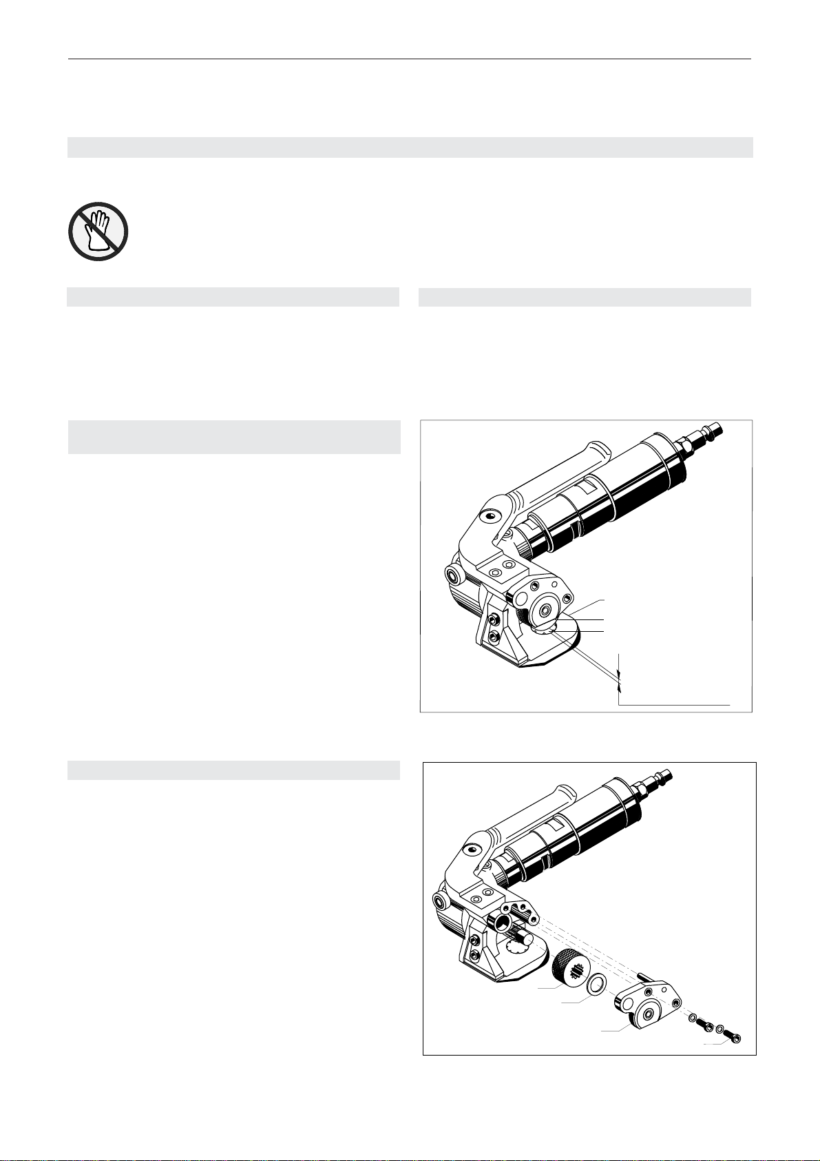
6TEILELISTE1831.003.001/10
Pos. Artikel-Nr. Benennung Stück Pos. Artikel-Nr. Benennung Stück
1 1831.032.002 Getriebegehäuse komplett 1
2 1831.032.001 Lagerplatte 1
3 1832.039.002 Deckel 1
4 1831.011.001 Grundplatte 1
5 1831.011.002 Knickleiste , 0,8 - 1,0 mm 1
6 1821.080.001 Griff 1
7 1821.025.001 Mutter 1
8 1821.034.002 Welle 1
*9 1821.040.001 Spannrad 1
*10 1821.043.001 Spannmatrize 1
11 1821.034.001 Achse 1
12 1821.020.010 Distanzbüchse 1
13 1821.063.001 ZTA-Ritzel 1
14 1821.063.002 ZTA-Rad 1
15
16
17
18
19
20 1820.010.213 Druckfeder 1
21 1917.401.145 Distanzscheibe, ø 14/26 x 0,5 2
22 1933.820.120 Nadelhülse, ø 20/26 x 12 1
23 1933.722.162 Nadelhülse, ø 22/28 x 16 1
24 1933.914.120 Nadelbüchse, ø 14/20 x 12 2
25 1933.910.120 Nadelbüchse, ø 10/14 x 12 1
26 1934.330.151 Axiallager, ø 15/28,4 x 6 1
27 1934.310.350 Axiallager, ø 35 1
28 1921.304.120 Zylinderstift, ø 4m6 x 12 1
29 1910.505.082 Gewindestift, M 5 x 8 1
30 1911.006.168 Zylinderschraube, M 6 x 16 2
31 1911.005.149 Zylinderschraube, M 5 x 14 4
32 1911.005.108 Zylinderschraube, M 5 x 10 2
33
34 1921.305.160 Zylinderstift, ø 5m6 x 16 2
35
36 1919.606.072 Sicherungsscheibe, M 6 2
37 1919.605.062 Sicherungsscheibe, M 5 6
38
39
40 1921.306.220 Zylinderstift, ø 6m6 x 22 1
41 1912.908.006 Ringschraube, M 6 (bei Bedarf) 1
42
43
44
45
46
47
48
49
50 1894.425.000 Druckluftmotor, LZB 33 A 005-64 1
51 1895.312.003 Scheibenfeder 1
52
53
54
55
56
57
58
59
60
61
62
63
64
65
66
67 1820.090.068 Ölschild 1
68 1940.311.721 Stecknippel, G 1/4" 1
69 1821.090.003 Firmenschild 1
AusführungUSA/CAN
68 1820.100.019 Stecknippel, 1/4" NPT 1
71 1820.100.017 Übergangsnippel, G 1/4"x1/4" NPT 1
BeiBestellungenArtikel-Nr. und Stückzahl angeben Explosionszeichnung:siehe Seite 10
*Empfohlene Ersatzteile

08.05/WE
10
ORGAPACK CR 208 P
CR 208 P 1831.003.001/8
51
50
7
26
20
22
13
1
27
32
37 3
21
14
b)
31
37
25
6
11
5
29
4
10
23
8
12
9
21 40
372
24
24
e)
68
b)
30
36
28
69
02.12.04 sm/hp
(41)
b)Loctite 243 e)Loctite 577
*
e)
71
b)
31
34
*Linksgewinde

08.05/WE 11
ORGAPACK CR 208 P
1 1894.425.002 Ventilgehäuse 1
2 1894.425.011 Getriebegehäuse (Rückseite) 1
3 1894.432.026 Schalldämpfer 1
4 1894.432.027 Sieb 1
5 1894.432.005 Kugellager 1
6 1894.432.004 Lagerplatte hinten 1
7 1894.432.006 Stift 1
8 1894.432.003 Zylinder 1
9 1894.422.001 Rotor 1
10 1894.422.002 Lamelle 5
11 1894.432.002 Keil 1
12 1894.432.009 Lagerplatte vorn 1
13 1894.432.001 Kugellager 1
14 1894.432.013 Scheibe 1
15 1894.432.021 Kugellager 4
16 1894.332.015 Achse 2
17 1894.332.016 Nadelkranz 2
18 1894.422.003 Planetenrad 2
19 1894.422.004 Planetenwelle 1
20 1894.432.025 Gewindebüchse 1
21 1894.432.024 Tellerfeder 2
22 1894.432.017 Achse 2
23 1894.332.024 Lagernadel 32
24 1894.432.016 Planetenrad 2
25 1894.432.018 Planetenwelle 1
26 1894.432.023 Getriebegehäuse (Frontseite) 1
27 1894.432.020 Dichtung 1
28 1894.432.022 Frontstück 1
29 1894.324.005 Reduziernippel 1
30 1894.425.005 O-Ring 2
31 1894.425.006 Distanzring 1
32 1894.425.008 Betätigungsring 1
33 1894.425.007 Federscheibe 1
34 1894.425.004 Stift 1
35 1894.324.008 O-Ring 1
36 1894.425.009 O-Ring 1
37 1894.425.003 Ventilstössel 1
38 1894.324.003 Druckfeder 1
39 1894.324.001 O-Ring 1
40 1894.324.002 Verschluss-Schraube 1
7TEILELISTEDRUCKLUFTMOTOR1894.425.000/1
Pos. Artikel-Nr. Benennung Stück
Bei Bestellungen immer Artikel-Nr. und Stückzahl angeben Explosionszeichnung: siehe Seite 12

08.05/WE
12
ORGAPACK CR 208 P
15
15
27
28
21
1
13
12
11
20
24
23
26
3
2
5
7
6
10
9
8
4
16
18
17
25
16
17 18
23
24
15
15
22
22
*
1894.425.000/1 28.5.98 wb/ja
19
LZB 33 A005-64
*
*
*
14
33
32
29
35
36
37
38
39
40
31
30
34
*Linksgewinde

08.05/WE 13
ORGAPACK CR 208 P
Weight 4,1 kg (9.25 lbs.)
Dimensions L = 340mm(13.5")
W = 110mm(4.35")
H = 110mm(4.35")
Tensioningforce 8400N
Tensioningspeed 90 mm/s (3.5"/s)
Airpressure max. 6 bar static
Airconsumtion
fortensioning 6,4 Nl/s (29 gal./s)
Airconnection G 1/4" (1/4" NPT)
Connectioncoupling Partno1940.306.732
Emissionsoundpressure
levels,measurement
type A (EN ISO 11202) LpA 76 dB (A)
Vibrationsathandle
(ENISO8662-1) ah,w < 2,5 ms-2
STEELSTRAP
Strapwidth 19, 25 or 32 mm
(3/4", 1" or 11/4")
Strap thickness 0.6–1.00mm
(.023"–.039")
Tensilestrength Uptoapprox.1100N/mm2
ORGAPACK-SEALERS
– OR-V 40 P (single notch)
– OR-V41P(double notches)
ORGAPACK-SEALS
Strap width 19 mm (3/4") CSP617
Strap width 25 mm (1") CSP717
Strap width 32 mm (11/4") CSP817
1TECHNICAL DATA
TABLE OF CONTENTS
1 Technical data 13
2 General information 14
2.1 Information on environmental
protection 14
2.2 Compressed-airconnection 14
3 Safetyinstructions 15
4 Operatinginstructions 16
4.1 Operatingthetool 16
5 Preventive and corrective maintenance 18
5.1 Adjustingstrap tension 18
5.2 Cleaningthetool 18
5.3 Settingtheclearancebetween
tensioningwheelandtensionplug 18
5.4 Cleaning/replacingthetensioningwheel 18
6 Partslist 19
Explosiondrawing 20
7 Parts list air motor 21
Explositiondrawingairmotor 22
We take sole responsibility for declaring that the
tool CR 208 P, to which this declaration refers, is in
fullcompliancewiththecurrentrequirementsof the
guidelines laid down by the council on 22th June
1998(98/37/EEC),“MachineGuidelines“.
Accordingto norm:
EN 292-1, EN 292-2, EN 349, EN 983, EN 1050
prEN792-2
CH-8953Dietikon,April2001
Manager Manager
Sales & Marketing: Engineering:
R.Kieffer M.Binder
DECLARATION OF AGREEMENT

08.05/WE
14
ORGAPACK CR 208 P
CAUTION!
Used where there is
danger to life and health.
WARNING!
Used for danger which
can cause material
damage.
NOTE!
Used for general infor-
mation and information
which if not followed can
cause faults in the
operating sequence.
2GENERAL INFORMATION
These operating instructions are intended to simplify
familiarisation with the strapping tool and the possi-
bilities of application for the intended purpose. The
operating instructions contain important information
concerning the safe, proper and efficient use of the
strapping tool. Observation of the information will help
to avoid danger, reduce repairs and stoppages and
increase the reliability and service life of the strapping
tool.
The operating instructions must always be available
at the place of operation of the strapping tool. They
must be read and observed by all persons concerned
with work on the strapping tool. This work specifically
includes operation, refilling of operating material, fault
elimination and maintenance.
In addition to the operating instructions and the regu-
lations for accident prevention effective in the country
of use and place of application, the recognised tech-
nical regulations for safety and proper working must
also be observed.
2.1 INFORMATIONONENVIRONMENTAL
PROTECTION
This tool is manufactured without any physical or
chemical substances which could be dangerous to
health. For disposal of all the parts, the governmental
instructions must be observed.
2.2 COMPRESSED-AIRCONNECTION
The air motor is lubricated by oil mist of the compres-
sedair.Properly prepared compressed airis therefore
essentialfor trouble-free operation of thetool. This can
onlybe ensured by a reliablyfunctioning maintenance
unit,consisting of waterseparator, pressurereducing
valvewith pressure gaugeand oil mistlubricator.
The oil mist lubricator should supply sufficient oil. The
length of the hose between the CR 208 P and the
maintenance unit should not exceed 5 m (15 ft). The
internal diameter of the pipe should be at least 10 mm
(3/8“). It must be ensured that the hose does not form
loops, where oil can collect.

08.05/WE 15
ORGAPACK CR 208 P
Use for the intended purpose
Thetool is intendedfor strapping heavy round
packages, bundles of sectional steel, pipes etc.
(togetherwithsealer).
This tool was designed and manufactured for safe
handling during the strapping operation.
The tool processes steel straps only.
Possible misuse
The use of plastic straps is not possible.
3SAFETY INSTRUCTIONS
Inform yourself!
Read the operating
instructions carefully.
Protect yourself!
When operating the tool,
wear eye, face and hand
protection (cut-proof
gloves).
Warning:
Strap will snap forward!
When cutting the strap,
holdtheupperportionand
standsafelyawayfrom
the strap.
Caution:
The lower strap will snap
forward.
Warning:
Strap could break!
Do not stand in line with
the strap while it is ten-
sioned.Thestrapcould
break!
Caution:
Danger of squeezing!
Do not put your fingers
into the tension wheel
area.
Caution:
Only strap packed
goods!
Do not put hands or other
partsofthebodybetween
the strap and the package
duringthestrapping
process.
Do not exceed the air
pressure!
Donot exeed therecom-
mendedairpressure
Usesafetycoupling!
Forconnectingthe air
hose to the tool, use only
asafetycoupling
Do not use a bottled
air or gas source!
Do not operate tis tool by
usining a bottled air or
gassource
Caution:
If work is carried out
usingaspring balancer,
onlyaspringbalancer
that complies with the
safetyregulationsmay
beused.
OriginalORGAPACK
seals must be used
exclusively.
Original ORGAPACK
spare parts must be
used exclusively!
Not using original spare
parts will dissolve the
warrantyand theliability.
jklsfjklsdj
lksdfjkl
jkljsdllkjjkljsd
fkljjklkjkljsdafj
asdfjklkjjkljklj
ksldafkjkljkl
jkljklkljsdafjlkj
jkljjkljklkljljlk
max.6 bar
0
2
4
6810
12
14
16
ORGAPACK
Original
ORGAPACK
Original

08.05/WE
16
ORGAPACK CR 208 P
1
1
4OPERATING INSTUCTIONS
4.1 OPERATING THE TOOL
– Draw the strap from the dispenser, slide the strap
through the seal (4/1) and wind strap around the
package.
– Push the strap start a second time through the
seal.
Fig. 1
Fig. 2
Fig. 3
– Bend the strap start below the seal 3–4 cm (1–2“).
– Pull the strap tightly by hand and take a portion of
the strap leading to the dispenser with the left hand
approx. 20 cm (8“) away from the seal.
– Hold the tool with the right hand and pull the motor
againstlever.
– Insert the strap below the feed wheel, at the same
time push the tool forward against the seal.
– Releasethelever.

08.05/WE 17
ORGAPACK CR 208 P
Tensioning
– Turnthe knurled wheel attherear of theairmotor
clockwise, the strap is tensioned. Do not turn off
the motor.
Foradjustmentofstraptension(by
pressureregulatoronmaintenanceunit),
seechapter5.1.
Fig. 4
Fig. 5
Sealing
– Seal the straps using sealer (see operating instruc-
tion OR-V 40 P/OR-V 41 P).
Fig. 6
Cut off strap
– Swivel the tool CR 208 P up and down until the
strap is cut off. Switch off the air motor by turning
the knurled wheel counterclockwise.

08.05/WE
18
ORGAPACK CR 208 P
43
21
Fig. 8
5.3 SETTINGTHECLEARENCEBETWEEN
TENSIONINGWHEELANDTENSIONPLUG
Spacebetweentensioningwheel(7/2) and tension plug
(7/3)musthave0,1–0,25 mm (.0039"–.0098").
– Disconnect the tool from the air supply.
– Loosen set srew (7/1).
– The space can be adjusted by turning the tension
plug (7/3), with a screwdriver. For less space turn
clockwise, for more space turn counterclockwise.
– Tightenset screw (7/1).Thepointed head ofthe set
screw must be located in one of the notches of the
toothedplate.
5.4 CLEANING/REPLACINGTHE
TENSIONINGWHEEL
Remove
–Disconnect the tool from the air supply.
– Loosen two cylinder screw (8/1).
– Carefullyremovethebearingplate(8/2)fromtension
shaft.
– Takeoffthecounterwasher(8/3)andthetensioning
wheel(8/4).Checkthetensioningwheel,cleanor
replace if necessary.
Install
– Install the parts in reverse order.
5PREVENTIVEANDCORRECTIVE MAINTENANCE
Fig. 7
2
3
1
0,1–0,25 mm
(.0039"–.0098")
5.1 ADJUSTINGTHESTRAPTENSION
The air pressure is regulated by the pressure
regulator on the maintenance unit. With running air
motor, the pressure should be minimum 4 bar (60 psi)
and maximum 6 bar (90 psi).
Thetool always hasto be disconnected
fromtheairsupply,before maintenance- or
repairworkisperformed.
5.2 CLEANINGTHETOOL
– Thetool should be regulary cleaned.The easiest
way to do this, is to use compressed air and to blow
out the dust (wear eye protection).

08.05/WE 19
ORGAPACK CR 208 P
6PARTS LIST 1831.003.001/10
Whenordering please indicatepart number andquantity Explosion drawing seepage 20
*Recommended spare parts
Pos. Part no Part name Quantity Pos. Part no Part name Quantity
1 1831.032.002 Gear housing complete 1
2 1831.032.001 Bearing plate 1
3 1832.039.002 Cover 1
4 1831.011.001 Base plate 1
5 1831.011.002 Knee piece, 0,8 - 1,0 mm 1
6 1821.080.001 Lever 1
7 1821.025.001 Nut 1
8 1821.034.002 Shaft 1
*9 1821.040.001 Tension wheel 1
*10 1821.043.001 Tension plug 1
11 1821.034.001 Axe 1
12 1821.020.010 Spacer bushing 1
13 1821.063.001 ZTA-Pinion 1
14 1821.063.002 ZTA-Wheel 1
15
16
17
18
19
20 1820.010.213 Compression spring 1
21 1917.401.145 Distance washer, ø 14/26 x 0,5 2
22 1933.820.120 Needle bushing, ø 20/26 x 12 1
23 1933.722.162 Needle bushing, ø 22/28 x 16 1
24 1933.914.120 Needle bushing, ø 14/20 x 12 2
25 1933.910.120 Needle bushing, ø 10/14 x 12 1
26 1934.330.151 Trust bearing, ø 15/28,4 x 6 1
27 1934.310.350 Trust bearing, ø 35 1
28 1921.304.120 Cylindric pin, ø 4m6 x 12 1
29 1910.505.082 Threaded pin, M 5 x 8 1
30 1911.006.168 Cylinder screw, M 6 x 16 2
31 1911.005.149 Cylinder screw, M 5 x 14 4
32 1911.005.108 Cylinder screw, M 5 x 10 2
33
34 1921.305.160 Cylindric pin, ø 5m6 x 16 2
35
36 1919.606.072 Lock washer, M 6 2
37 1919.605.062 Lock washer, M 5 6
38
39
40 1921.306.220 Cylindric pin, ø 6m6 x22
41 1912.908.006 Ring screw, M 6 (on request) 1
42
43
44
45
46
47
48
49
50 1894.425.000 Compressed air motor,
LZB 33 A 005-64 1
51 1895.312.003 Key 1
52
53
54
55
56
57
58
59
60
61
62
63
64
65
66
67 1820.090.068 Oil tag 1
68 1940.311.721 Air plug, G 1/4" 1
69 1821.090.003 Name tag 1
VariationUSA/CAN
68 1820.100.019 Air plug, 1/4" NPT 1
71 1820.100.017 Transition connector,
G 1/4" x 1/4" NPT 1

08.05/WE
20
ORGAPACK CR 208 P
CR 208 P 1831.003.001/8
51
50
7
26
20
22
13
1
27
32
37 3
21
14
b)
31
37
25
6
11
5
29
4
10
23
8
12
9
21 40
372
24
24
e)
68
b)
30
36
28
69
02.12.04 sm/hp
(41)
b)Loctite 243 e)Loctite 577
*
e)
71
b)
31
34
*Left-handedthread
Table of contents
Languages:
Other Orgapack Packaging Equipment manuals