Oriental motor OPX-2A User manual

Thank you for purchasing an Oriental Motor product.
This Manual describes product handling procedures and safety precautions.
•Please read it thoroughly to ensure safe operation.
•Always keep the manual where it is readily available.
HM-60273-2
Data Setter OPX-2A
PKA Series
OPERATING MANUAL
1 Safety precautions ................... 2
2 Introduction .............................. 3
3 Preparation................................ 4
4 Installation and connection of
the OPX-2A............................... 8
5 Screen transitions................... 10
6 Monitor mode ......................... 16
7 Data mode ............................... 21
8 Parameter mode..................... 25
9 Test mode................................. 32
10 Copy mode............................... 37

Safety precautions
2
1 Safety precautions
The precautions described below are intended to prevent danger or injury to the user and other personnel through
safe, correct use of the product. Use the product only after carefully reading and fully understanding these
instructions.
Also read the“Safety precautions”sections in the operating manuals that came with the product you are combining
with the OPX-2A.
Handling the product without observing the instructions that accompany a "Warning"
symbol may result in serious injury or death.
Handling the product without observing the instructions that accompany a "Caution"
symbol may result in injury or property damage.
The items under this heading contain important handling instructions that the user
should observe to ensure safe use of the product.
General
•Do not use the product in explosive or corrosive environments, in the presence of ammable gases, locations
subjected to splashing water, or near combustibles. Doing so may result in re, electric shock or injury.
•Assign qualied personnel the task of installing, wiring, operating/controlling, inspecting and troubleshooting the
product. Failure to do so may result in re, electric shock or injury.
•When the protective function is triggered, rst stop operation and turn o the power, then turn on the power
again after removing the cause. Continuing the operation without removing the cause of the problem may cause
malfunction of the motor, leading to injury or damage to equipment.
Repair, disassembly and modication
•Do not disassemble or modify the data setter. This may cause electric shock or injury. Refer all such internal
inspections and repairs to the branch or sales oce from which you purchased the product.
General
•Do not use the motor beyond the specications. Doing so may result in electric shock, injury or damage to
equipment.
Operation
•Provide an emergency stop device or emergency stop circuit external to the equipment so that the entire
equipment will operate safely in the event of a system failure or malfunction. Failure to do so may result in injury.
Disposal
•Dispose the product correctly in accordance with laws and regulations, or instructions of local governments.

Introduction
3
2 Introduction
Only qualied personnel of electrical and mechanical engineering should work with the product.
Use the product correctly after thoroughly reading the“1 Safety precautions”on p.2. In addition, be sure to
observe the contents described in warning, caution, and note in this manual.
The product described in this manual has been designed and manufactured to be incorporated in general industrial
equipment. Do not use for any other purpose. Oriental Motor Co., Ltd. is not responsible for any damage caused
through failure to observe this warning.
Overview of the product
The OPX-2A is a data setter that lets you set operating data and parameters, perform monitoring, etc.
So that the OPX-2A is used correctly and safely, thoroughly read the “PKA Series USER MANUAL” and understand the
basic operating procedures and other details of the motor.
Features of OPX-2A
The OPX-2A can be used to save data in addition to setting of operation data and parameters.
There are four destinations (data banks) to save data.
OPX-2A
Data bank 1
Data bank 0
Data bank 2
Data bank 3
Motor
Set operation data and
parameters.
Up to 4 sets of operation data
and parameters can be saved.
Copy one set to the motor.
Motor
The OPX-2A can be used for the following purposes:
•Operation data and parameters of the motor can be set.
•The operating status of the motor can be monitored.
•The operation data and parameters set in the motor can be saved to the OPX-2A.
•The operation data and parameters saved in the OPX-2A can be copied to another motor connected to the
OPX-2A.
Specications
Connection Mini DIN, 8 pins
External dimensions 96(W)× 72(H)× 21.5(D) mm
[3.78 (W) × 2.83 (H) × 0.85 (D) in.]
Cable length 5 m (16.4 ft.)
Mass 0.25 kg (8.8 oz)
RoHS Directive
The products do not contain the substances exceeding the restriction values of RoHS Directive. (2011/65/EU)

Preparation
4
3 Preparation
This chapter explains the items you should know before using the OPX-2A.
3-1 Checking the product
Verify that the items listed below are included. Report any missing or damaged items to the branch or sales oce
from which you purchased the product.
•Data setter OPX-2A............. 1 unit
•Information.............................. 1 copy
3-2 Names and functions of parts
Display
This area shows the motor position,
operation data, parameters, alarms, etc.
LED indicators
These LED indicators are used to indicate
the operation mode of the OPX-2A and
the motor status.
Use this button to select data or change the
displayed item or move to the next lower level
.
Use these buttons to change the selected item or set data and parameters.
Use these buttons to increase or decrease the value or
change the selected item.
Use these buttons to navigate through each data
or parameter to a desired digit.
• Switches the operation mode.
• Moves to the upper level.
• Stop the motor immediately while being
operated in test mode.
Notation
In this manual, keys are denoted by symbols, such as .
In gures, a simplied illustration of the display and LED indicators is used, as shown below.

Preparation
5
3-3 How to read the display
The display consists of 7-segment LEDs. (The number“5” and alphabet “S” are the same.)
1234567890
A
· Numbers
+
-
· Signs
· Alphabets
BCDE FGHI JKL
MN OP QR STUV
WY
How to read the LED indicators
When the operation mode is changed or an alarm or warning generates, a corresponding LED will be lit.
While the motor is operating or the edit lock function is enabled, the condition is also indicated by the illumination of
a corresponding LED.
Lit in the copy mode
Lit in the test modeLit in the parameter mode
Lit in the data mode
Lit in the monitor mode
Lit when an alarm is presen
t
Lit when a warning is present
Lit while the motor is operating Not used
Lit when the edit lock func
tion is enabled
Not used
Not used
3-4 Types of operation modes
The OPX-2A has multiple operation modes, and the operation
mode will change every time the key is pressed. The
display starts in the monitor mode when the power is turned
on.
When the operation mode is changed, the LED indicator
corresponding to the previous mode will turn o and the one
corresponding to the new mode will be lit. Identify the current
operation mode based on the LED indicator currently lit.
Monitor mode
(MON)
Copy mode
(COPY)
Test mode
(TEST)
Parameter mode
(PAR)
Data mode
(DATA)
The mode changes
every time the key
is pressed.

Preparation
6
3-5 Basic operations of the OPX-2A
Use the six keys to set data and operate the motor.
Operation ow
The OPX-2A is operated according to the ow shown below.
Level 2: Item selection screen Level 3
move to the
previous item.
Level 1: Top screen in each mode
12
3
4
Useto
navigate through
the modes.
to the lower level.
Useto move
to the upper level.
Useto move
Useto
move to the
next item.
Useto
1. Use the key to select a desired operation mode appropriate for your intended operation.
Example: If you want to use a function in the test mode, press the key to select the test mode (indicated by
a lit “TEST”LED). The top screen of the test mode is displayed.
2. Press the key to move to the lower level.
3. Use the keys to select a desired item.
4. To move to the lower level, press the key. To return to the previous level, press the key.
As explained above, use the key to navigate through the levels and use the keys to select a desired
item. This is the basic operation ow.
If the key on the OPX-2A is pressed while internal processing is being performed, the top
screen will not change to any of its sub-screens and “mEm-bUSy” will be shown on the display.
Be sure to wait until all internal processing is completed, before pressing the key.

Preparation
7
How to input values
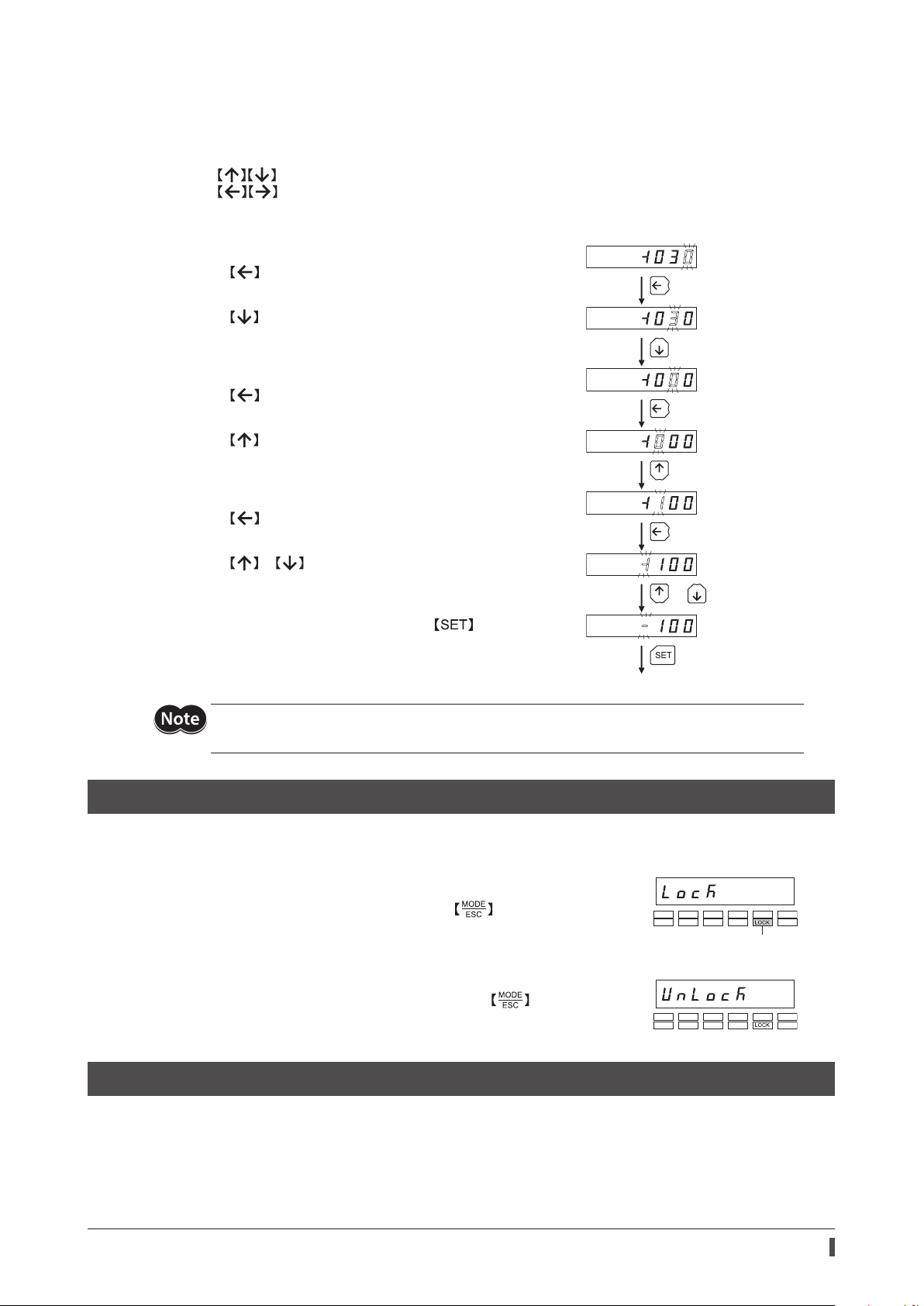
As an example, how to change “+30” to “−100” is explained.
Basic operations
•Use the keys to increase/decrease the value or change the sign.
Use the keys to move to the digit you want to edit.
•If positive and negative values are dierentiated, each value is preceded by a sign.
•You can edit the digit currently blinking.
1. First, change the 10’s place from "3" to "0."
Press the key once to move to the 10’s digit you want to edit.
Conrmed
Once
or
3 times
Once
Once
Once
Once
2. Press the key three times to change the value to "0."
3. Next, change the 100’s place from "0" to "1."
Press the key once to move to the 100’s digit you want to edit.
4. Press the key once to change the value to "1."
5. Next, change the sign.
Press the key once to move to the sign digit you want to edit.
6. Press the or key once to change the sign to "−."
7. After all digits have been changed, press the key to conrm
the value.
All digits comprising the value blink for approx. 2 seconds.
If the value you have input is outside the setting range, "Error" will be displayed for 1 second.
If this error display appears, input a dierent value that falls within the setting range.
3-6 Edit lock function
Enable the edit lock function if you want to prevent operation data and parameters from being edited or cleared.
Operation data and parameters cannot be changed or deleted while the edit lock function is enabled.
zSetting the edit lock function
In the top screen of each operation mode, press the key for at least
5 seconds. The display will show "LocK" and the edit lock function will be enabled.
The "LOCK" LED in the LED indicator area will also be lit.
“LOCK” lit
zCanceling the edit lock function
Again in the top screen of each operation mode, press the key for at least
5 seconds. The display will show "UnLocK" and the edit lock function will be
cancelled. The "LOCK" LED in the LED indicator area will turn o.
3-7 Rewriting the motor’s non-volatile memory
Operation data and parameters are saved to the motor’s non-volatile memory. The non-volatile memory can be
rewritten approximately 100,000 times. The non-volatile memory will be rewritten after one of the following
operations is performed:
•Edit any operation data or parameter
•Download data from the OPX-2A to the motor
•Initialize motor operation data and parameters

Installation and connection of the OPX-2A
8
4 Installation and connection of the
OPX-2A
4-1 Location for installation
The OPX-2A is designed and manufactured to be incorporated in equipment. Install it in a well-ventilated location
that provides easy access for inspection. The location must also satisfy the following conditions:
•Inside an enclosure that is installed indoors (provide vent holes)
•Operating ambient temperature 0 to +40 °C (+32 to +104 °F) (non-freezing)
•Operating ambient humidity 85% or less (no condensation)
•Area that is free of explosive atmosphere or toxic gas (such as sulfuric gas) or liquid
•Area not exposed to direct sun
•Area free of excessive amount of dust, iron particles or the like
•Area not subject to splashing water (rain, water droplets), oil (oil droplets) or other liquids
•Area free of excessive salt
•Area not subject to continuous vibration or excessive shocks
•Area free of excessive electromagnetic noise (from welders, power machinery, etc.)
•Area free of radioactive materials, magnetic elds or vacuum
•1000 m (3300 ft.) or less above sea level
4-2 Installation method
Using a metal plate of 1 to 3 mm (0.04 to 0.12 in.) in thickness, insert the OPX-2A into the mounting hole from the
front side and securely set the OPX-2A in place.
· Dimension of mounting hole
[mm (in.)]
92 +0.8
0 (3.62 )
+0.031
0
68 +0.7
0
(2.68 )
+0.028
0
Removing method
Press all of the four hooks provided on top and bottom of the OPX-2A.
In this condition, press the OPX-2A forward to release.
Hook

Installation and connection of the OPX-2A
9
4-3 Connecting to the motor
1. Connect the OPX-2A cable and accessory data setter cable CC001IF-CA (sold separately).
2. Turn on the motor power after connecting the data setter cable CC001IF-CA to the data edit connector (CN4)
on the motor.
Data setter cable
CC001IF-CA
Data edit connector (CN4)
Motor
•When operation data and parameters are set on the OPX-2A, they will be stored in the motor.
Once stored in the motor, the data will not be cleared even after the OPX-2A is disconnected from
the motor.
•Turning on the power to the motor will also turn on the power to the OPX-2A. Turning o the
motor power will turn o the OPX-2A power.
•Turn o the motor power before connecting or disconnecting the OPX-2A cable.
4-4 Error display on OPX-2A screen
The following error message is displayed on the OPX-2A screen.
Error display Description Remedial action
A communication error occurred
between the OPX-2A and motor.
•Check if the OPX-2A is connected securely.
•Check if the cables connecting the OPX-2A are
disconnected or damaged.
•The OPX-2A or the communication part of the
motor may have damaged. Contact your nearest
Oriental Motor sales oce.

Screen transitions
10
5 Screen transitions
There are the following restrictions while the edit lock function is eective.
• Data mode, parameter mode:
Although they are displayed on the screen, they are unable to operate.
• Clearing the alarm and warning records, clear data, position preset, teaching, copy mode:
They are not displayed on the screen.
If the HMI input is in an OFF state, functions other than monitor mode, upload, or verication cannot
be executed.
Command speed
Operation number
Selected number
Command position
Present warning
Direct I/O monitor
Top screen of the
monitor mode
Input monitor
Output monitor
Warning record 1 (latest)
Warning record 10 (oldest)
Clear warning records
Present alarm
Alarm record 1 (latest)
Alarm record 10 (oldest)
Alarm reset
Clear alarm records
Processing is
in progress
(blinking display)
Processing is
in progress
(blinking display)
Processing is
in progress
(blinking display)
Top screen at power ON
In the lower level except the top screen, press the key to return to the previous level.

Screen transitions
11
Operation data No.
selection 0
Operation data No.
selection 63
Top screen of the
data mode to Parameter mode
Positioning mode
Position
Operating speed
Operating mode
Dwell time
Sequential
positioning
Acceleration
Deceleration
Clear data
Single
Numerical entry
Clear
Link1
Link2
Processing is in progress
(blinking display)
Writing of data is in progress
(blinking display)
Writing of data is in progress
(blinking display)
Writing of data is in progress
(blinking display)
Writing of data is
in progress
(blinking display)
Numerical entry Writing of data is in progress
(blinking display)
Numerical entry Writing of data is in progress
(blinking display)
Numerical entry Writing of data is in progress
(blinking display)
Numerical entry Writing of data is in progress
(blinking display)
Numerical entry Writing of data is in progress
(blinking display)
Broken line indicates that data writing cannot be executed when internal
key is pressed.
“mEm-bUSy" is displayed even when the
processing is in progress via RS-485 communication.

Screen transitions
12
Data mode
Top screen of the
test mode
Direct I/O test
JOG operation
Data No. select
operation
Output test
Perform positioning
operation
Operation is in
progress
Operation data No.
selection 0
Operation data No.
selection 63
Processing is
in progress
(blinking display)
Perform positioning
operation Processing is
in progress
(blinking display)
Input test
Output test
Top screen of the
parameter mode
Parameter setting
Parameter selection
(Example: Electronic
gear A)
Writing of data is
in progress
(blinking display)
In the lower level except the top screen, press the key to return to the previous level.
Entering the parameter ID
the display to move to the
setting screen for each
parameter.
and pressing will cause

Screen transitions
13
Return-to-home
operation
Writing of data is
in progress
(blinking display)
Writing of data is
in progress
(blinking display)
Processing is in progress
(blinking display)
Processing is in progress
(blinking display)
Operation data No.
selection 0
Operation data No.
selection 63
Position preset
Teaching
Perform position
preset
Perform return-to-home
operation
Perform teaching
Copy mode
Broken line indicates that data writing cannot be ex
ecuted when internal
key is pressed.
“mEm-bUSy" is displayed even when the
processing is in progress via RS-485 communication.

Screen transitions
14
Top screen of the
copy mode
Download
Data bank selection 0
Data bank selection 3
Upload
Test mode
Processing is in progress
(blinking display)
Processing is in progress
(blinking display)
Data bank selection 2 Processing is in progress
(blinking display)
Data bank selection 1 Processing is in progress
(blinking display)
Data bank selection 0
Data bank selection 3
Processing is in progress
(blinking display)
Processing is in progress
(blinking display)
Data bank selection 2 Processing is in progress
(blinking display)
Data bank selection 1 Processing is in progress
(blinking display)
In the lower level except the top screen, press the key to return to the previous level.

Screen transitions
15
Data bank selection 0
Data bank selection 3
Verication result: Matched
Verication result: Unmatched
Verication
Processing is in progress
(blinking display)
Processing is in progress
(blinking display)
Processing is in progress
(blinking display)
Initialization
Initialize parameters
Initialize operation data
Initialize all data
Data bank selection 2
Data bank selection 1
Monitor mode
Broken line indicates that data writing cannot be executed when internal
key is pressed.
“mEm-bUSy" is displayed even when the
processing is in progress via RS-485 communication.

Monitor mode
16
6 Monitor mode
6-1 Overview of the monitor mode
zMonitoring the operating status
You can monitor the motor speed, command position, operation data number corresponding to the current
operation, and operation data number currently selected in real time.
A range capable to monitor with the OPX-2A is from −19,999,999 to 19,999,999 with up to eight
digit numbers. However, only seven digit numbers can be shown on the display of the OPX-2A, so
only the last seven digit numbers are shown when the monitored value is eight digit numbers, and a
dot is marked on the lower right of the display.
•Display example
Actual value −19,999,999 −10,000,001 −10,000,000 10,000,000 10,000,001 19,999,999
Displayed value −9999999. −0000001. −0000000. 0000000. 0000001. 9999999.
zChecking alarms/warnings, clearing alarm/warning records, and resetting alarms
•If an alarm or warning generates, a corresponding alarm code or warning code will be displayed. You can check the
code to identify the details of the alarm/warning.
•Up to ten most recent alarms/warnings can be displayed, starting from the latest one.
•You can reset the alarms currently present.
•You can clear alarm and warning records.
zChecking I/O signals
You can check the ON/OFF status of each I/O signal of the motor.
6-2 Operation in the monitor mode
1. Use the key to select the monitor mode.
2. Press the key in the top screen of the monitor mode.
3. Use the keys to select the item you want to monitor.
Speed
Operation number
Selected number
Command position
Warning
Direct I/O monitor
Alarm
Top screen of the
monitor mode

Monitor mode
17
6-3 Monitor items
Motor speed
You can check the motor rotation speed (unit: Hz).
While the motor is rotating in the CCW direction, “−” is shown in front of the displayed value. If the speed is indicated
by an absolute value, no sign is shown to indicate the rotation direction. You can select the value display format using
the “display mode of the data setter speed” parameter [ID: 480].
Command position
You can check the command position of the motor with reference to the home position.
If a resolution is set, an appropriate value based on the resolution is shown as steps.
Operation number
You can check the operation data number corresponding to the data used in the current positioning operation.
Selected number
You can check the operation data number currently selected.
Alarm
When an alarm generates, a corresponding alarm code will be displayed.
You can also reset alarms or check and clear alarm records.
Alarm record 1 (latest)
Alarm record 10
(oldest)
Alarm reset
Clear alarm records
Alarm is being reset
(blinking display)
Alarm records are being
cleared (blink
ing display)
Alarm record 2
Pr
esent alarm
* If operations are limited by the edit lock function, the screen text in gray is not shown.
•Do not turn o the motor power while an alarm is being reset or alarm records are being cleared
(=while the display is blinking). Doing so may damage the data.
•If operations are limited by the edit lock function, the alarm records cannot be cleared.
•Some alarms cannot be reset on the OPX-2A. Refer to “Alarm code list” on p.18 for details. To
reset these alarms, you must cycle the motor power.

Monitor mode
18
Alarm code list
Code Alarm name Resetting on the OPX-2A Number of ALM LED blinks
21h Main circuit overheat
Possible
2
22h Overvoltage 3
25h Undervoltage
34h Command pulse error 2
41h EEPROM error Not possible 9
4Ah Return-to-home incomplete
Possible
7
60h ±LS both sides active
61h Reverse limit sensor connection
62h Home seeking error
63h No HOMES
64h TIM, SLIT input error
66h Overtravel
67h Software overtravel
6Ah Home seeking oset error
70h Invalid operation data
71h Electronic gear setting error Not possible
81h Network bus error Possible
83h Communication switch setting error Not possible
84h RS-485 communication error
Possible85h RS-485 communication timeout
8Eh Network converter error
F0h CPU error Not possible Lit
zHow to reset an alarm
1. While an alarm is displayed, press the key to move to the lower level.
2. Press the key to select the alarm reset screen.
3. Press the key.
The alarm is reset.
zHow to check an alarm record
You can check up to ten most recent alarms, starting from the latest one.
1. While an alarm is displayed, press the key to move to the lower level.
The latest alarm is displayed.
2. Press the key.
The second latest alarm is displayed.
3. Every time the key is pressed, the next older alarm will be displayed. Use the keys to select the
alarm record you want to check.
zHow to clear all alarm records
You can clear all alarm records at once.
1. While an alarm is displayed, press the key to move to the lower level.
2. Press the key three times and select the alarm record clear screen.
3. Press the key.
All alarm records are cleared.

Monitor mode
19
Warning
When a warning generates, a corresponding warning code will be displayed.
You can also check or clear warning records.
Warning record 1 (latest)
Warning record 10
(oldest)
Clear warning records
Wa
rning records are being
cleared (blinking display)
Warning record 2
Pr
esent warning
* If operations are limited by the edit lock function, the screen text in gray is not shown.
•Do not turn o the motor power while warning records are being cleared (=while the display is
blinking). Doing so may damage the data.
•If operations are limited by the edit lock function, the warning records cannot be cleared.
•You can also clear the warning records by turning o the motor power.
Warning code list
Code Warning name
21h Main circuit overheat
22h Overvoltage
25h Undervoltage
71h Electronic gear setting error
84h RS-485 communication error
zHow to check a warning record
You can check up to ten most recent warnings, starting from the latest one.
1. While a warning is displayed, press the key to move to the lower level.
The latest warning is displayed.
2. Press the key.
The second latest warning is displayed.
3. Every time the key is pressed, the next older warning will be displayed. Use the keys to select the
warning record you want to check.
zHow to clear all warning records
You can clear all warning records at once.
1. While a warning is displayed, press the key to move to the lower level.
2. Press the key and select the warning record clear screen.
3. Press the key.
All warning records are cleared.

Monitor mode
20
Direct I/O monitor
You can check the ON/OFF status of each I/O signal of the motor.
Input monitor
Output monitor
Top screen of
direc
t I/O monitor
Each digit on the 7-segment LED display corresponds to a signal. If the signal is ON, the corresponding digit is lit. If the
signal is OFF, the digit is unlit.
zInput monitor
IN0
IN1
IN2
IN3
zOutput monitor
OUT0
OUT1
Other manuals for OPX-2A
3
This manual suits for next models
1
Table of contents
Other Oriental motor Control Unit manuals

Oriental motor
Oriental motor RKII Series User manual

Oriental motor
Oriental motor ASTEP AR Series User manual

Oriental motor
Oriental motor OPX-2A User manual

Oriental motor
Oriental motor AR Series User manual

Oriental motor
Oriental motor ASTEP AZ Series User manual

Oriental motor
Oriental motor ASTEP AR Series User manual

Oriental motor
Oriental motor MSS W Series User manual

Oriental motor
Oriental motor ASTEP AR Series User manual

Oriental motor
Oriental motor PKP Series User manual

Oriental motor
Oriental motor OPX-2A User manual