Oriental motor OPX-2A User manual

HP-5049-3
Data setter OPX-2A
For the BLV Series
OPERATING MANUAL
Thank you for purchasing an Oriental Motor product.
This Operating Manual describes product handling procedures and safety precautions.
•Please read it thoroughly to ensure safe operation.
•Always keep the manual where it is readily available.

−2−
1 Safety precautions .............................. 3
2 Introduction ......................................... 4
3 Preparation .......................................... 5
3.1 Checking the product ............................... 5
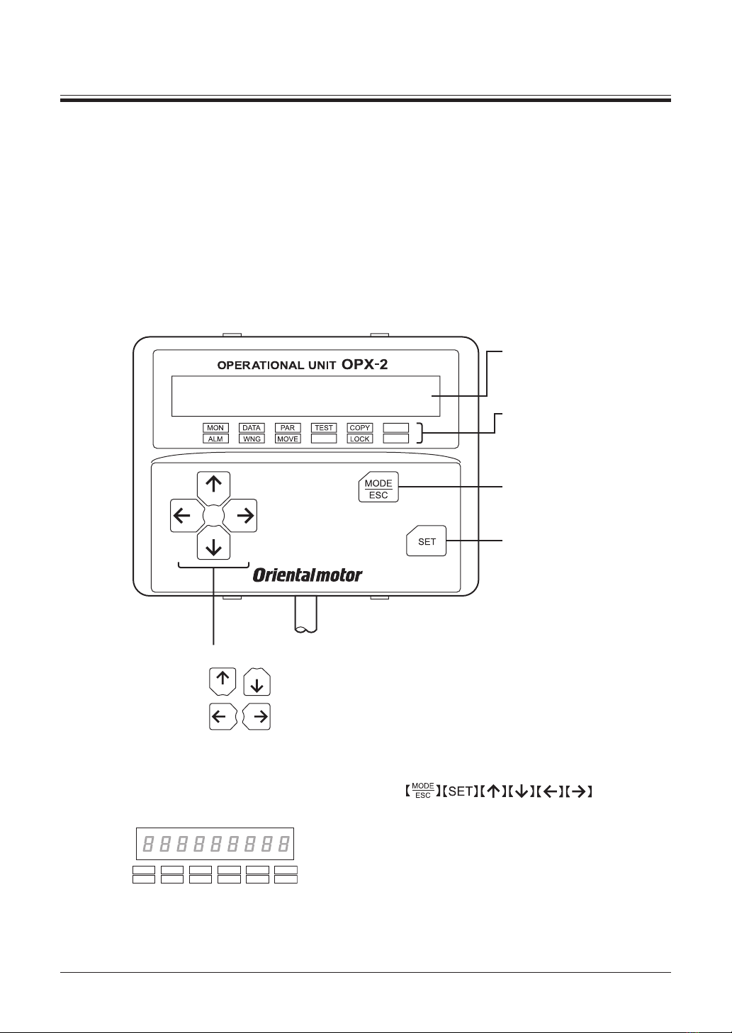
3.2 Names and functions of parts .................. 5
3.3 How to read the display ........................... 6
3.4 How to read the LED indicators ............... 6
3.5 Types of operation modes ....................... 6
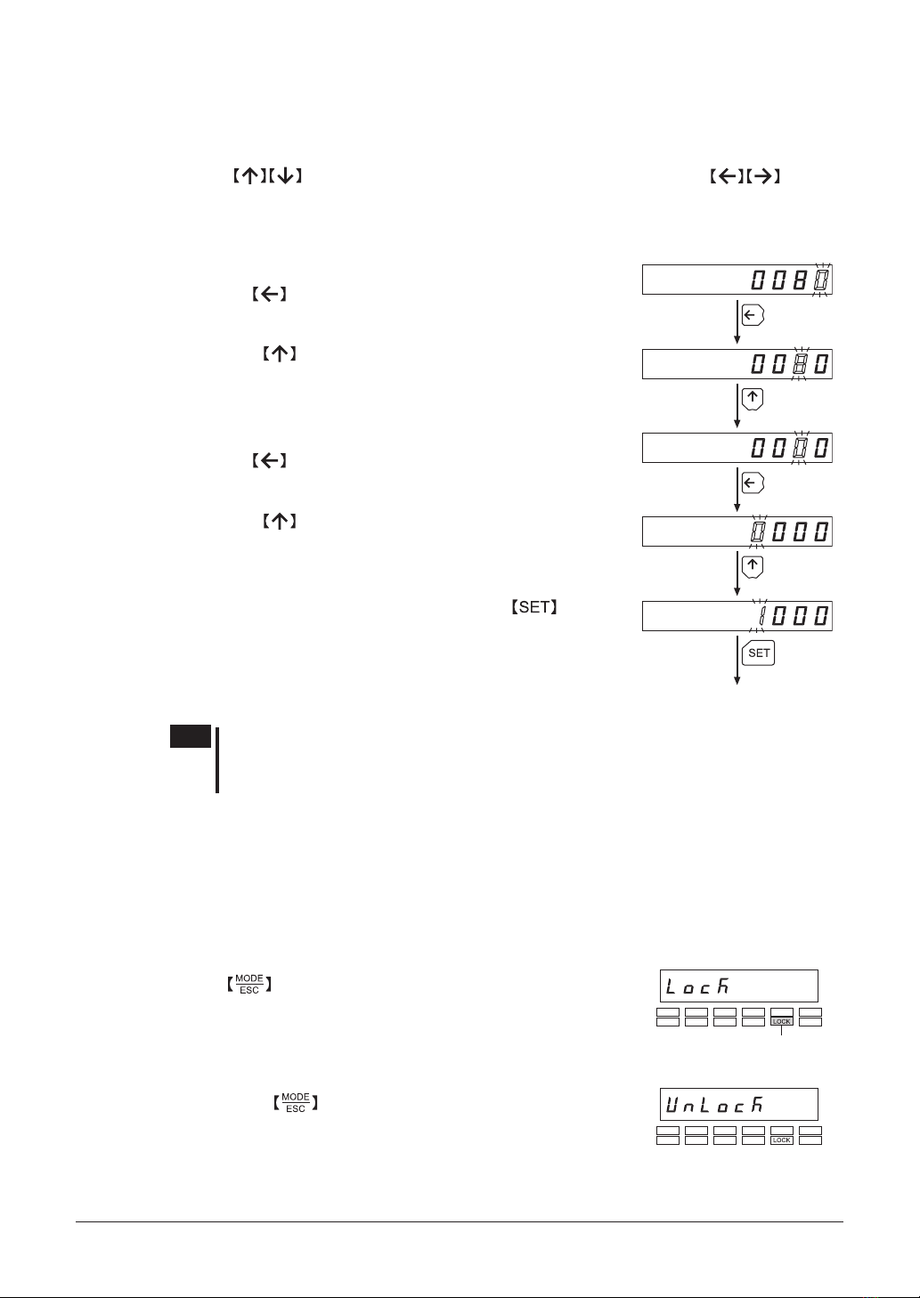
3.6 Basic operations of the OPX-2A .............. 7
3.7 Edit lock function ..................................... 8
3.8 Rewriting the driver’s non-volatile
memory .................................................... 9
4 Installation and connection of the
OPX-2A ............................................. 10
4.1 Location for installation .......................... 10
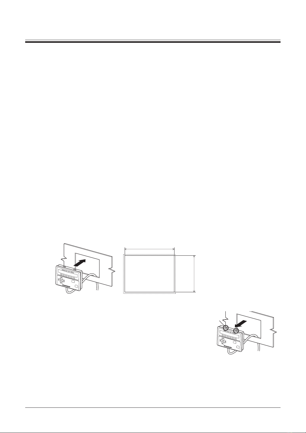
4.2 Installation method ................................ 10
4.3 Connecting to the driver .........................11
4.4 Error display on OPX-2A screen ............11
5 Screen transitions ............................. 12
6 Monitor mode .................................... 16
6.1 Overview of the monitor mode ............... 16
6.2 Monitored items ..................................... 16
7 Data mode ......................................... 19
7.1 Setting items .......................................... 19
7.2 Initializing operation data ....................... 19
8 Parameter mode ............................... 20
8.1 Parameter ID ......................................... 20
8.2 Setting example ..................................... 30
9 Test mode .......................................... 32
9.1 Overview of the test mode ..................... 32
9.2 I/O test ................................................... 32
9.3 JOG operation ....................................... 33
10 Copy mode ........................................ 34
10.1 Overview of the copy mode ................... 34
10.2 Downloading to the driver ...................... 35
10.3 Uploading to the OPX-2A ...................... 35
10.4 Verifying data ......................................... 36
10.5 Initializing driver data ............................. 36
Table of contents

−3−
Safety precautions
1 Safety precautions
The precautions described below are intended to prevent danger or injury to the user and other
personnel through safe, correct use of the product. Use the product only after carefully reading and fully
understanding these instructions.
Also read the "Safety precautions" sections in the USER MANUAL that came with the product you are
combining with the OPX-2A.
Handling the product without observing the instructions that accompany a
"Warning" symbol may result in serious injury or death.
Handling the product without observing the instructions that accompany a
"Caution" symbol may result in injury or property damage.
Note
The items under this heading contain important handling instructions that the
user should observe to ensure safe use of the product.
General
•Do not use the product in explosive or corrosive environments, in the presence of ammable gases,
locations subjected to splashing water, or near combustibles. Doing so may result in re, electric shock
or injury.
•Only qualied and educated personnel should be allowed to perform installation, connection, operation
and inspection/troubleshooting of the product. Handling by unqualied and uneducated personnel may
result in re, electric shock or injury.
•When the driver’s protective function is triggered, rst remove the cause and then clear the protective
function. Continuing the operation without removing the cause of the problem may cause malfunction
of the motor and driver, leading to injury or damage to equipment.
Repair, disassembly and modication
•Do not disassemble or modify the data setter. This may cause electric shock or injury. Refer all such
internal inspections and repairs to the branch or sales ofce from which you purchased the product.
General
•Do not use the motor, gearhead and driver in conditions exceeding the specications. Doing so may
result in electric shock, injury or damage to equipment.
Operation
•Provide an emergency stop device or emergency stop circuit so that the entire equipment will operate
safely in the event of a system failure or malfunction. Failure to do so may result in injury.
Disposal
•Dispose the product correctly in accordance with laws and regulations, or instructions of local
governments.

Introduction
−4−
2 Introduction
Only qualied personnel should work with the product.
Use the product correctly after thoroughly reading the section "1 Safety precautions" on page.3.
The product described in this manual has been designed and manufactured to be incorporated in general
industrial equipment. Do not use for any other purpose. Oriental Motor Co., Ltd. is not responsible for
any damage caused through failure to observe this warning.
Overview of the product
The OPX-2A is a data setter that lets you set operation data and parameters, perform monitoring, etc.
Use the OPX-2A properly and safely after thoroughly reading the "BLV Series USER MANUAL" and
understanding the basic operating procedures and other details.
Features of OPX-2A
The OPX-2A can be used to save data in addition to setting of operation data and parameters.
There are four destinations (data banks) to save data.
OPX-2A
Data bank 1
Data bank 0
Data bank 2
Data bank 3
Driver
Driver
Set operation data and parameters.
Up to 4 sets of operation data and
parameters can be saved.
Copy any one of the
4 sets to the driver.
The OPX-2A can be used for the following purposes:
•Operation data and parameters of the driver can be set.
•The operating status of the motor can be monitored.
•Operation data and parameters set in the driver can be saved to the OPX-2A.
•Operation data and parameters saved in the OPX-2A can be copied to other drivers.
Specications
Connection Mini DIN, 8 pins
External dimensions 96 (W)×72 (H)×21.5 (D) mm
[3.78 (W)×2.83 (H)×0.85 (D) in.]
Cable length 5 m (16.4 ft.)
Mass 0.25 kg (8.8 oz)
RoHS Directive
The products do not contain the substances exceeding the restriction values of RoHS Directive
(2011/65/EU).

−5−
Preparation
3 Preparation
This chapter explains the items you should know before using the OPX-2A.
3.1 Checking the product
Verify that the items listed below are included. Report any missing or damaged items to the branch or
sales ofce from which you purchased the product.
•Data setter OPX-2A .................................. 1 unit
•Information ................................................ 1 copy
3.2 Names and functions of parts
Display
This area shows the motor
position, operation data,
parameters, alarms, etc.
LED indicators
These LED indicators are used
to indicate the operation mode
of the OPX-2A and the driver
status.
Use this button to select data or
change the displayed item or
move to the lower level.
Use this button to change the
operation mode or move to the
upper level.
Use these buttons to change the selected item or set data and parameters.
Use these buttons to increase or decrease the value
or change the selected item.
Use these buttons to navigate through each data
or parameter to a desired digit.
Notation
In this manual, keys are denoted by symbols, such as .
In gures, a simplied illustration of the display and LED indicators is used, as shown below.

Preparation
−6−
3.3 How to read the display
The display consists of 7-segment LEDs. (The number "5" and alphabet "S" are the same.)
1234567890
A
• Numbers
+
-
• Signs
• Alphabets
B C D E F G H I J
K L M N O P Q R S T
U V W Y
3.4 How to read the LED indicators
When the operation mode is changed or an alarm or warning generates, a corresponding LED will be lit.
While the motor is operating or the edit lock function is enabled, the condition is also indicated by the
illumination of a corresponding LED.
Lit in the copy mode
Lit in the test modeLit in the parameter mode
Lit in the data mode
Lit in the monitor mode
Lit while an alarm is present
Lit while a warning is present
Lit while the motor is operating Not used
Lit while the edit lock function is enabled
Not used
Not used
3.5 Types of operation modes
The OPX-2A has multiple operation modes. The
operation mode will change every time the
key is pressed.
The display starts in the monitor mode when the
power is turned on.
When the operation mode is changed, the LED
indicator corresponding to the previous mode will
turn off and the one corresponding to the new
mode will be lit. Identify the present operation
mode based on the LED indicator currently lit.
Monitor mode
(MON)
Copy mode
(COPY)
Test mode
(TEST)
Parameter mode
(PAR)
Data mode
(DATA)
The mode changes
every time the key
is pressed.

−7−
Preparation
3.6 Basic operations of the OPX-2A
Use the six keys to set data and operate the motor.
Operation ow
The OPX-2A is operated according to the ow shown below.
Level 2: Item selection screen Level 3Level 1: Top screen in each mode
12
3
4
Use the
key to navigate
through the
modes.
Use the
key to move
to the lower level.
toUse
move to the
previous item.
toUse
move to the
next item.
Use the
key to move
to the upper level.
1. Use the key to select a desired operation mode appropriate for your intended
operation.
Example: If you want to use a function in the test mode, press the key to select the test mode
(indicated by a lit "TEST" LED).
The top screen of the test mode is displayed.
2. Press the key to move to the lower level.
3. Use the keys to select a desired item.
4. To move to the lower level, press the key. To return to the previous level, press the
key.
As explained above, use the key to navigate through the levels and use the keys to
select a desired item. This is the basic operation ow.
Note If the key is pressed while the driver performs the internal processing, the
screen cannot change to any lower level from the top screen, and "mEm-bUSY" is
displayed. Be sure to wait until all internal processing is completed, before pressing
the key.

Preparation
−8−
How to input values
As an example, how to change the rotation speed from "80" r/min to "1000" r/min is explained.
Basic operations
•Use the keys to increase/decrease the value or change the sign. Use the keys to
move to the digit you want to edit.
•If positive and negative values are differentiated, each value is preceded by a sign.
•The digit currently blinking can be edited.
1. First, change the 10’s place from "8" to "0."
Press the key once to move to the 10’s digit you want to edit.
Determined
Once
Twice
Twice
Once
2. Press the key twice to change the value to "0."
3. Next, change the 1000’s place from "0" to "1."
Press the key twice to move to the 1000’s digit you want to
edit.
4. Press the key once to change the value to "1."
5. After all digits have been changed, press the key to
determine the value.
All digits comprising the value blink for approximately 2 seconds.
Note If the value you have input is outside the setting range, "Error" will be displayed for
1 second. If this error display appears, input a different value that falls within the
setting range.
3.7 Edit lock function
Enable the edit lock function if you want to prevent operation data and parameters from being edited or
cleared.
Operation data and parameters cannot be changed or deleted while the edit lock function is enabled.
•Setting the edit lock function
Press the key for at least 5 seconds on the top screen in each mode.
The display will show "LocK" and the edit lock function will be enabled.
The "LOCK" LED in the LED indicator area will also be lit.
"LOCK" lit
•Canceling the edit lock function
Again, press the key for at least 5 seconds on the top screen in each
mode.
The display will show "UnLocK" and the edit lock function will be
cancelled.
The "LOCK" LED in the LED indicator area will turn off.

−9−
Preparation
3.8 Rewriting the driver’s non-volatile memory
Operation data and parameters are saved to the driver’s non-volatile memory. The non-volatile memory
can be rewritten approximately 100,000 times. The non-volatile memory will be rewritten after one of
the following operations is performed:
•Edit any operation data or parameter
•Download data from the OPX-2A to the driver
•Initialize driver operation data and parameters

Installation and connection of the OPX-2A
−10−
4 Installation and connection of the OPX-2A
4.1 Location for installation
The OPX-2A is designed and manufactured to be incorporated in equipment.
Install it in a well-ventilated location that provides easy access for inspection. The location must also
satisfy the following conditions:
•Inside an enclosure that is installed indoors (provide vent holes)
•Operating ambient temperature 0 to +40 °C (+32 to +104 °F) (non-freezing)
•Operating ambient humidity 85% or less (non-condensing)
•Area that is free of explosive atmosphere or toxic gas (such as sulfuric gas) or liquid
•Area not exposed to direct sun
•Area free of excessive amount of dust, iron particles or the like
•Area not subject to splashing water (rain, water droplets), oil (oil droplets) or other liquids
•Area free of excessive salt
•Area not subject to continuous vibration or excessive shocks
•Area free of excessive electromagnetic noise (from welders, power machinery, etc.)
•Area free of radioactive materials, magnetic elds or vacuum
•1000 m (3300 ft.) or less above sea level
4.2 Installation method
Using a metal plate of 1 to 3 mm (0.04 to 0.12 in.) in thickness, insert the OPX-2A into the mounting
hole from the front side and securely attach it.
92 +0.8
0 (3.62 )
+0.031
0
68 +0.7
0
(2.68 )
+0.028
0
• Dimension of mounting hole [mm (in.)]
Removing method
Press all of the four hooks provided on top and bottom of the
OPX-2A.
In this condition, press the OPX-2A forward to release.
Hook

−11−
Installation and connection of the OPX-2A
4.3 Connecting to the driver
Plug the connector attached to the end of
the OPX-2A cable into the communication
connector (CN7) on the driver, and then turn on
the power to the driver.
Communication
connector
(CN7)
Note
•When operation data and parameters are set on the OPX-2A, they will be stored in
the driver. Once stored in the driver, the data will not be cleared even after the
OPX-2A is disconnected from the driver.
•Turning on the power to the driver will also turn on the power to the OPX-2A.
Turning off the driver power will turn off the OPX-2A power.
•Turn off the driver power before connecting or disconnecting the OPX-2A cable.
4.4 Error display on OPX-2A screen
The following error message is displayed on the OPX-2A screen.
Error display Description Remedial action
A communication error
occurred between the
OPX-2A and driver.
•Check if the OPX-2A is connected securely.
•Check if the OPX-2A cable is disconnected or
damaged.
•The OPX-2A or the communication part of the
driver may have damaged. Contact your nearest
Oriental Motor sales ofce.

Screen transitions
−12−
5 Screen transitions
Operation speed
Operation speed
Load factor
Operation data
number
Conveyor transfer
speed
Present warning
I/O monitor
Monitor mode
Top screen
Input monitor
Output monitor
Voltage monitor of
external speed setting
Warning record 1 (latest)
Warning record 10 (oldest)
Clear warning records
Present alarm
Alarm record 1 (latest)
Alarm record 10 (oldest)
Alarm reset
Clear alarm records
Processing is
in progress
(blinking display)
Processing is
in progress
(blinking display)
Processing is
in progress
(blinking display)
Use these buttons to move.:
Use this button to move or execute.:
In the lower level except the top screen, press the key to return to the previous level.

−13−
Screen transitions
Operation data
number selection 0
Operation data
number selection 7
Data mode
Parameter mode
Rotation speed
Torque limiting value
Acceleration time
Deceleration time
Numerical entry
Numerical entry
Numerical entry
Numerical entry
Writing of data is in progress
(blinking display)
Writing of data is in progress
(blinking display)
Writing of data is in progress
(blinking display)
Writing of data is in progress
(blinking display)
When internal processing is in progress, data writing cannot
be executed via RS-485 communication.
"mEm-bUSy" is displayed even when the key is pressed.
Note
•The following limitations are present while the edit lock function is enabled.
· Data mode, parameter mode: These are displayed in the screen but cannot be operated.
· Clearing of the alarm and warning records, copy mode: These are not displayed in the screen.
•When the HMI input is in an OFF state, all functions of the test mode cannot executed.
Downloading and initializing are also disabled.

Screen transitions
−14−
Data mode
Test mode
I/O test
JOG operation
Output test
Operation is in progress
Input test
Voltage test of
external speed setting
Output test
Parameter mode
Parameter setting
Parameter selection
(Example: speed increasing ratio)
Writing of data
is in progress
(blinking display)
Use these buttons to move.:
Use this button to move or execute.:
In the lower level except the top screen, press the key to return to the previous level.
Enter the parameter ID and press
key, then move to the setting
screen for each parameter.

−15−
Screen transitions
Monitor mode
Copy mode
Download
Download
Data bank selection 0
Data bank selection 3
Data bank selection 0
Data bank selection 3
Data bank selection 0
Data bank selection 3
Verification result: Matched
Verification result: Unmatched
Upload
Verify
Initialization
Processing is
in progress
(blinking display)
Processing is
in progress
(blinking display)
Processing is
in progress
(blinking display)
Processing is
in progress
(blinking display)
Processing is
in progress
(blinking display)
Processing is
in progress
(blinking display)
Processing is
in progress
(blinking display)
Initialize parameters
Initialize operation data
Initialize all data
When internal processing is in progress, data writing cannot
be executed via RS-485 communication.
"mEm-bUSy" is displayed even when the key is pressed.

Monitor mode
−16−
6 Monitor mode
6.1 Overview of the monitor mode
•Monitoring the operating status
You can monitor the motor operation speed, conveyor transfer speed, load factor and operation data
number corresponding to the current operation.
•Checking alarms/warnings, clearing alarm/warning records, and resetting alarms
•If an alarm or warning generates, a corresponding alarm code or warning code will be displayed.
You can check the code to identify the details of the alarm/warning.
•Up to the ten most recent alarms/warnings can be displayed, starting from the latest one.
•You can reset the alarms currently present.
•You can clear alarm/warning records.
•Checking I/O signals
You can check the ON/OFF status of each I/O signal of the driver.
6.2 Monitored items
Operation speed (unit: r/min)
You can check the rotation speed of the motor.
While the motor is rotating in the counter clockwise direction (CCW), “−” is shown in front of the
displayed value.
This speed can also be displayed as the absolute value. To display the rotation speed as absolute value,
change the setting of the data-setter speed display parameter [ID: 480].
You can also display the rotation speed of the motor as the rotation speed of the gear output shaft. To do
this, set the speed reduction ratio parameter [ID: 2085] and speed reduction ratio decimal digit setting
parameter [ID: 2086].
It is also possible to increase the rotation speed and display the increased speed. For this, set the speed
increasing ratio parameter [ID: 2087].
Conveyor transfer speed (unit: m/min)
You can check the conveyor transfer speed.
Set the conveyor speed reduction ratio parameter [ID: 2088] and conveyor speed reduction ratio decimal
digit setting parameter [ID: 2089]. It is also possible to increase the rotation speed and display the
increased speed. For this, set the conveyor speed increasing ratio parameter [ID: 2090].
Load factor (unit: %)
You can check the generated torque of the motor. The current load factor is monitored based on the rated
torque being 100%.
Operation data number
You can check the operation data number corresponding to the current operation.

−17−
Monitor mode
Present alarm
When an alarm generates, the alarm code is displayed.
You can also reset alarms or check and clear alarm records.
Note
•Do not turn off the driver power while an alarm is being reset or alarm records are
being cleared (= while the display is blinking). Doing so may damage the data.
•When operations are limited by the edit lock function, the alarm records cannot be
cleared.
•Some alarms cannot be reset by the OPX-2A. For details, refer to the table below.
To reset these alarms, you must cycle the driver power.
Alarm code list
Code Alarm name Resetting on the
OPX-2A
Number of driver’s
ALARM LED blinks
20 Overcurrent Not possible 7
21 Main circuit overheat
Possible
9
22 Overvoltage 4
25 Undervoltage 5
28 Sensor error 3
2D Main circuit output error 14
30 Overload 2
31 Overspeed 6
41 EEPROM error Not possible 8
42 Sensor error during initialization
Possible
3
46 Initial operation error 11
6E External stop 10
81 Network bus error
12
83 Communication switches setting error Not possible
84 RS-485 communication error
Possible85 RS-485 communication timeout
8E Network converter error
Present warning
When a warning generates, the warning code is displayed.
You can also check or clear warning records.
Note
•Do not turn off the driver power while warning records are being cleared (= while the
display is blinking). Doing so may damage the data.
•When operations are limited by the edit lock function, the warning records cannot be
cleared.
•You can also clear warning records by cycling the driver power.
Warning code list
Code Warning name
21 Main circuit overheat
25 Undervoltage
30 Overload
6C Operation error
84 RS-485 communication error

Monitor mode
−18−
I/O monitor
You can check the ON/OFF status of each I/O signal of the driver.
Each digit on the 7-segment LED display corresponds to a signal. If the signal is ON, the corresponding
digit is lit. If the signal is OFF, the digit is unlit.
•Input monitor
•Output monitor
X0
X1
X2
X3
X4
X5
Y0
Y1
•Voltage monitor of external speed setting [V]
When setting the speed by means of an external
DC voltage, you can monitor whether voltage is
input. If 10 VDC is selected, a value corresponding
to one half the input voltage is displayed.

−19−
Data mode
7 Data mode
Up to eight sets of operation data can be set. Once set, the operation data is stored in the driver. The data
will not be lost even after the OPX-2A is disconnected from the driver.
Before setting operation data, read the USER MANUAL carefully to understand the basic operations,
functions and other details of the driver.
Note
•Operation data have signicant bearing on motor operation. Before setting any
operation data, make sure you fully understand the content of the data.
•If operations are limited by the edit lock function, the operation data cannot be
edited.
•Operation data can also be set by selecting the ID with the parameter mode.
•If key is pressed while executing the internal processing via RS-485
communication, “mEm-bUSy” may be displayed. Check "5 Screen transitions" on
p.12 when “mEm-bUSy” is displayed. Be sure to wait until all internal processing is
completed, before pressing the key.
7.1 Setting items
Item Initial
value Setting range Description Setting
unit
Rotation speed 0 0 r/min, and 80
to 4000 r/min Set the rotation speed. 1
Torque limiting
value*1 200 0 to 200% Set when limiting the operation torque. 1
Acceleration time*2 0.5 0.2 to 15.0 s Set the acceleration time over which to
reach the target speed. 0.1
Deceleration time*2 0.5 0.2 to 15.0 s Set the deceleration time over which to
reach the target speed. 0.1
*1 The initial value is motor starting torque. The rated torque being 100%.
*2 This is the case when being set digitally by the OPX-2A. If any analog setting mode (internal
potentiometer, external potentiometer or external DC voltage) is selected, the time over which to reach
the rated rotation speed (3000 r/min) is indicated. The actual acceleration time and deceleration time vary
depending on the conditions of use, load inertia, load torque and other settings specied by the customer.
Note If the value you have input is outside the setting range, “Error” will be displayed for 1
second. If this error display appears, input a different value that falls within the setting
range.
7.2 Initializing operation data
You can revert operation data saved in the driver to their initial values.
For details, refer to "10.5 Initializing driver data" on p.36.

Parameter mode
−20−
8 Parameter mode
You can set parameters relating to motor operation and control. These parameters are saved in the driver.
Before setting operation data, read the USER MANUAL carefully to understand the basic operations,
functions and other details of the driver.
Note
•Parameters have signicant bearing on motor operation. Before setting any
parameter, make sure you fully understand the content of the parameter.
•If operations are limited by the edit lock function, the parameters cannot be edited.
•If key is pressed while executing the internal processing via RS-485
communication, “mEm-bUSy” may be displayed. Check "5 Screen transitions" on
p.12 when “mEm-bUSy” is displayed. Be sure to wait until all internal processing is
completed, before pressing the key.
•If the value you have input is outside the setting range, “Error” will be displayed for
1 second. If this error display appears, input a different value that falls within the
setting range.
8.1 Parameter ID
There is an unique ID in each parameter. With the OPX-2A, set the parameter selecting the ID.
Timing for the setting value to become effective
When a parameter is changed, the timing for the new value to become effective varies depending on the
parameters, which are the following three types.
•Effective immediately
Executes the recalculation and setup immediately when writing the parameter.
•Effective after stopping the operation
Executes the recalculation and setup after stopping the operation.
•Effective after turning the power ON again
Executes the recalculation and setup after turning the power ON again.
Operation in the parameter mode
1. Use the key to select the parameter mode.
The “PAr” LED is lit.
2. Press the key in the top screen of the parameter mode.
The display changes to the application parameter select screen.
3. Use the keys to enter the parameter ID, and then press the key.
The display changes to the application parameter setting screen.
4. Use the keys to enter the setting value, and then press the key.
Other manuals for OPX-2A
3
Table of contents
Other Oriental motor Control Unit manuals

Oriental motor
Oriental motor OPX-2A User manual

Oriental motor
Oriental motor ASTEP AR Series User manual

Oriental motor
Oriental motor OPX-2A User manual

Oriental motor
Oriental motor MSS W Series User manual

Oriental motor
Oriental motor ASTEP AR Series User manual

Oriental motor
Oriental motor AR Series User manual

Oriental motor
Oriental motor ASTEP AZ Series User manual

Oriental motor
Oriental motor RKII Series User manual

Oriental motor
Oriental motor PKP Series User manual

Oriental motor
Oriental motor ASTEP AR Series User manual