2
Do not touch the rotating part (output shaft) during operation. Doing
so may result in injury.
Do not touch the terminals while conducting the insulation resistance
measurement or dielectric strength test. Doing so may result in electric
shock.
Provide a cover over the rotating part (output shaft) of the motor.
Failure to do so may result in injury.
Use a motor and driver only in the specied combination. Failure to do
so may result in re.
Provide an emergency stop device or emergency stop circuit external
to the equipment so that the entire equipment will operate safely in
the event of a system failure or malfunction. Failure to do so may result
in injury.
The motor surface temperature may exceed 70 °C
(158 °F) even under normal operating conditions.
If the operator is allowed to approach the motor in
operation, ax a warning label shown in the gure
on a conspicuous position. Failure to do so may
result in a skin burn(s).
Warning label
Precautions for use
This section covers restrictions and requirements the user should consider
when using the product.
•Be sure to use the accessory cable to connect the motor and
driver.
•When conducting the insulation resistance measurement or
the dielectric strength test, be sure to separate the connection
between the motor and the driver.
Conducting the insulation resistance measurement or dielectric strength test
with the motor and driver connected may result in damage to the product.
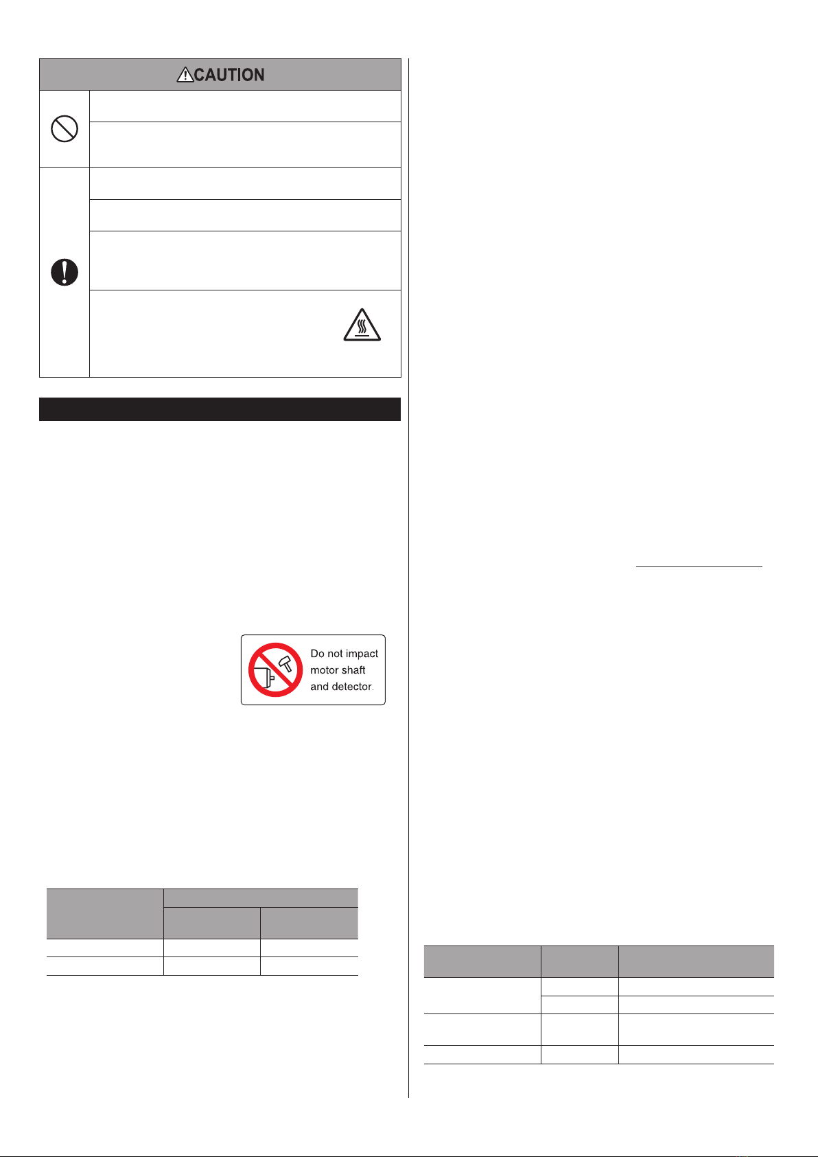
•Make sure not to hit or apply a strong impact on the motor
output shaft or the encoder (ABZO sensor).
Applying a strong impact on the
motor output shaft or the encoder
(ABZO sensor) may cause encoder
(ABZO sensor) damage or motor
malfunction. The warning label shown
in the right is attached on the motor. Warning label
•Do not move the encoder (ABZO sensor) toward a strong
magnetic eld.
A magnetic sensor is built into the encoder (ABZO sensor). If the motor is
installed close to equipment which generates a strong magnetic eld, the
encoder (ABZO sensor) may break or malfunction. Especially, since the motors
of frame size 20 mm (0.79 in.) and 28 mm (1.10 in.) are easily aected by a
magnetic eld, so make sure the environment at transportation and storage
as well as the installation location in use.
Keep the magnetic ux density on the surface of the encoder (ABZO sensor)
so as not to exceed the values in the table.
Motor frame size
Magnetic ux density
When transporting
and storing When operating
28 mm (1.10 in.) or less 5 mT 2 mT *
42 mm (1.65 in.) or more 10 mT 10 mT
* When the magnetic ux density is exceeding 1 mT and 2 mT or less, use in an
environment where the operating ambient temperature is exceeding 20 °C
(68 °F) and 40 °C (104 °F) or less.
•Meshing noise of mechanical sensor
A gear type mechanical sensor is built into the encoder (ABZO sensor).
Although the meshing noise of gears may generate, it is not malfunction.
•Do not apply a radial load and axial load in excess of the
specied permissible limit
Operating the motor under an excessive radial load or axial load may damage
the motor bearings (ball bearings). Be sure to operate the motor within the
specied permissible limit of radial load and axial load.
•Use the motor in conditions where its surface temperature will
not exceed 80 °C (176 °F).
The surface temperature on the motor case may exceed 80 °C (176 °F)
depending on operating conditions such as ambient temperature, operating
speed, duty cycle, and others. In order to protect the encoder (ABZO sensor),
use the motor so that the surface temperature on the motor case does not
exceed 80 °C (176 °F). If the encoder (ABZO sensor) temperature reaches the
upper limit, the motor overheat protection alarm will generate.
Use the geared motor in a condition where the gear case temperature does
not exceed 70 °C (158 °F), in order to prevent deterioration of grease and
parts in the gear case.
•Holding torque at standstill
The motor holding torque is reduced by the current cutback function of the
driver at motor standstill. When selecting a motor, check the holding torque
at motor standstill in the specications on the catalog.
•Do not use the electromagnetic brake to reduce speed or as a
safety brake.
Do not use the electromagnetic brake as a means to decelerate and stop the
motor. The brake hub of the electromagnetic brake will wear significantly
and the braking force will drop. Since the power o activated type
electromagnetic brake is equipped, it helps maintain the position of the load
when the power is cut o, but this brake cannot securely hold the load in
place. Accordingly, do not use the electromagnetic brake as a safety brake. To
use the electromagnetic brake to hold the load in place, do so after the motor
has stopped.
•Preventing electrical noise
For measures with regard to noise, refer to the OPERATING MANUAL Driver.
•Make sure to provide measures so that the key is not own o
when operating the motor with key in a state where a load is not
installed.
Flying o the key may result in injury or damage to equipment.
•Grease of encoder (ABZO sensor) and geared motor
On rare occasions, a small amount of grease may ooze out from the following
places.
yEncoder (ABZO sensor) mechanical part [motors of frame size 20 mm
(0.79 in.) and 28 mm (1.10 in.)]
yGeared motor
If there is concern over possible environmental damage resulting from
the leakage of grease, check for grease stains during regular inspections.
Alternatively, install an oil pan or other device to prevent leakage from
causing further damage. Oil leakage may lead to problems in the customer's
equipment or products.
•Peak torque of geared motor
Always operate the geared motor under a load not exceeding the peak
torque. If the load exceeds the peak torque, the gear will be damaged.
•Rotation direction of the gear output shaft
The relationship between the rotation direction of the motor shaft and that
of the gear output shaft changes as follows, depending on the gear type and
gear ratio.
Type of gear Gear ratio Rotation direction (relative to the
motor rotation direction)
TS geared 3.6, 7.2, 10 Same direction
20, 30 Opposite direction
FC geared, PS geared,
HPG geared All gear ratios Same direction
Harmonic geared All gear ratios Opposite direction


