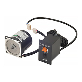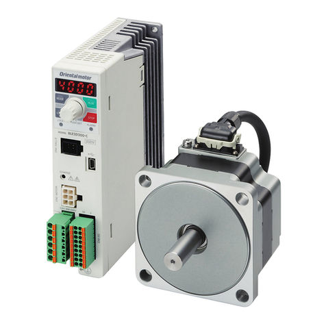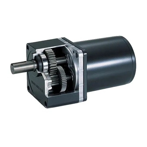
Checking the product
Open the package and confirm that all of the following items are available.
To verify that the unit you’ve purchased is the correct one, check the model
number shown on the nameplate. Should you find any item missing or
damaged, contact the Oriental Motor sales office where you purchased the
product.
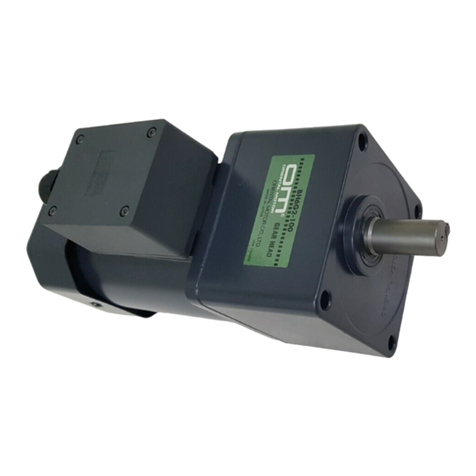
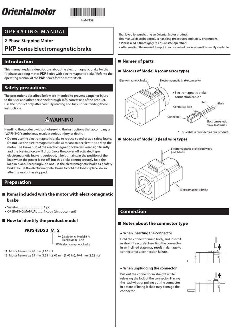
• Motor 1 unit
• Motor cable 0.6 m (2 ft.) 1 pc. (PK223PA (B)-SG-Lonly)
The square box in the motor type will contain a number representing the
gear ratio.
• Operating manual 1 copy
Installation
Location for installation
The motor is designed and manufactured for installation in equipment.
Install it in a well-ventilated location that provides easy access for inspection.
The location must also satisfy the following conditions:
• Inside an enclosure that is installed indoors (provide vent holes)
• Operating ambient temperature
-
10 to +50 °C (+14 to +122 °F) (non-freezing)
• Operating ambient humidity 85% or less (non-condensing)
• Area that is free of explosive atmosphere or toxic gas (such as sulfuric gas)
or liquid
• Area not exposed to direct sun
• Area free of excessive amount of dust, iron particles or the like
• Area not subject to splashing water (rains, water droplets), oil (oil
droplets) or other liquids
• Area free of excessive salt
• Area not subject to continuous vibration or excessive shocks
• Area free of excessive electromagnetic noise (from welders, power
machinery, etc.)
• Area free of radioactive materials, magnetic fields or vacuum
How to install the motor
Install the motor onto an appropriate flat metal plate having excellent
vibration resistance and heat conductivity. When installing the motor, secure
it with four screws (supplied) through the four tapped holes provided. Leave
no gap between the motor and plate.
Mounting-pilot holder
(countersunk or
drilled through)
Metal plate:
4 mm (0.16 in.)
or more
Cross-recessed
pan head screw (supplied)
Tapped hole
Motor model Screw size Tightening torque Effective depth
PK223PA-SG
PK223PB-SGM2.5 P0.45 0.5 N·m
(4.4 lb-in)
4 mm
(0.16 in.)
∗ The square box in the motor type will contain a number representing the
gear ratio.
Note Do not loosen the gearhead-attaching screws (four pcs.).
Installing a load
When connecting a load to the motor, align the centers of the motor’s output
shaft and load shaft. Be careful not to damage the output shaft or the bearings
when installing a coupling or pulley to the motor’s output shaft.
Permissible overhung load and permissible thrust load
The overhung load on the motor’s output shaft or gear output shaft must be
kept under the permissible values listed below. The thrust load must not
exceed 10 N (2.2 lb.).
[Unit: N (lb.)]
Distance from the top of motor's output shaft [mm (in.)]
0 mm (0 in.) 5 mm (0.2 in.) 10 mm (0.4 in.) 15 mm (0.6 in.)
15 (3.3) 17 (3.8) 20 (4.4) 23 (5.1)
Connection
(6)(5)(4)(3)(2)(1)
Pin assignments
Red
(3)
(4) Black
(5) Yellow
(6) Green
White
(2) Blue
(1)
BB
A
A
Wiring diagram
∗ ( ) indicates the pin number
The colors of lead wires shown apply to the supplied cable or optional motor
cable.
If you are using the connector set or when you are providing your own
connector or cable, connect based on the pin numbers shown.
The conforming connector and the cable are as follows.
Conforming connector and cable
Housing Contact Cable
51065-0600
(Molex)
50212-8XXX
(Molex)
AWG30 to 24 (0.05 to 0.2 mm2)
Cable outer diameter: Ø1.4 mm
(Ø0.055 in.) or less
Stripping the cable: 1.3 to 1.8 mm
(0.051 to 0.071 in.)
Note • Secure the motor connector cable in place so that the
connection won’t be subjected to stress induced by a
bent cable or the cable’s own mass. The cable’s radius
of curvature should be as large as possible.
• When removing the motor cable, pull it out horizontally
toward the output shaft. The motor may be damaged if
force is applied in any other direction.
Inspection
It is recommended that periodic inspections be conducted for the items listed
below after each operation of the motor. If an abnormal condition is noted,
discontinue any use and contact your nearest office.
• Check for any unusual noises in the motor’s bearings (ball bearings) or
other moving parts.
• Are there any loose connector connections, or any scratches or signs of
stress in the motor cable?
• Are the motor’s output shaft (or gear output shaft) and load shaft out of
alignment?
• Unauthorized reproduction or copying of all or part of this Operating
Manual is prohibited.
• Characteristics, specifications and dimensions are subject to change
without notice.
• , and are trademarks of Oriental
Motor Co., Ltd., and are registered in Japan and other countries.
Copyright ORIENTAL MOTOR CO., LTD. 2006
• Please contact your nearest Oriental Motor office for further information.
ORIENTAL MOTOR U.S.A. CORP.
Technical Support Line Tel:(800)468-3982
vailable from 7:30 AM to 5:00 PM, P.S.T.
E-mail: techsupport@orientalmotor.com
www.orientalmotor.com
ORIENTAL MOTOR (EUROPA) GmbH
Headquarters and Düsseldorf Office Tel:0211-5206700 Fax:0211-52067099
Munich Office Tel:08131-59880 Fax:08131-598888
Hamburg Office Tel:040-76910443 Fax:040-76910445
ORIENTAL MOTOR (UK) LTD. ORIENTAL MOTOR (FRANCE) SARL
Tel:01256-347090 Fax:01256-347099 Tel:01 47 86 97 50 Fax:01 47 82 45 16
ORIENTAL MOTOR ITALIA s.r.l. TAIWAN ORIENTAL MOTOR CO., LTD.
Tel:02-93906346 Fax:02-93906348 Tel:(02)8228-0707 Fax:(02)8228-0708
SINGAPORE ORIENTAL MOTOR PTE. LTD.
Tel:(6745)7344 Fax:(6745)9405
ORIENTAL MOTOR (MALAYSIA) SDN. BHD.
Tel:(03)79545778 Fax:(03)79541528
INA ORIENTAL MOTOR CO., LTD.
KOREA
Tel:(032)822-2042~3 Fax:(032)819-8745
ORIENTAL MOTOR CO., LTD.
Headquarters Tokyo, Japan
Tel:(03)3835-0684 Fax:(03)3835-1890 Printed on Recycled Pape
