Origin live ALLIANCE User manual

INTRODUCTION
Thank you for ordering an Origin Live arm. We trust you
will enjoy getting closer to the original sound and
appreciating your music in a new way.
Please give special attention to underlined text in these
instructions.
Photos and diagrams cover a range of arms and illustrate
concepts – do not expect exact representations of your
specific arm.
Notes:
a It may seem there is “play” in the bearings - this is a
design feature. The high grade bearings for horizontal
and vertical movement are “floated” inside their
housings to allow slight movement rather than rigidly
coupling them to the structure. These bearings are self
centering so you need not be concerned about apparent
movement.
b The sound of new arms and rewires will improve
significantly over the first 40 to 100 hours of running
time as wires burn in.
Mounting Requirements
Arm mounting varies depending on the make of your
turntable. This section caters for various scenarios.
Geometry & dimensions
You do not need a mounting template.
For standard Origin Live arms with effective
length of 9.5 inch (240mm)
The arm mounting hole diameter should be 23mm
to 24.5 mm.
Centre of mounting hole to centre of platter should
be 222mm (plus or minus 1mm tolerance .
For 12 inch arms (309mm)
Dimensions are same as above, but mounting hole
to centre of platter is 295.6mm
Page 1
ARM CLIP
HEADSHELL
ARM
TUBE
LIFT LOWER CURVED REST
COUNTERWEI HT YOKE
REAR STUB
LIFT LOWER LEVER
ARM
PLATE
Instructions for
ALLIANCE, ONYX,
SILVER & ZE HYR
I n s t r u c t i o n s b y O r i g i n l i v e 1 1 / 2 0 1 6 ©
***essential reading***

eight consideration
Origin Live arms can be raised by approx 16mm using
VTA adjustment. However performance is optimized
with the arm raised as little as possible. Ideally the
height from the top of armboard to top of platter should
be 24mm but not lower.
If this dimension is significantly larger on your deck,
you can use spacing washers – a 4mm Acrylic washer is
included for this purpose. This should be placed directly
on top of your armboard before fitting the arm.
There are other methods of adjusting armboard height
which may be advised by your turntable manufacturer.
Achieve Mounting Conditions
If your deck already has correct mounting dimensions
then skip the next section and read “Mounting the Arm”.
If your deck does not yet have the correct geometry then
alternatives are as follows.
Modify your existing armboard
You can probably modify your existing arm board to
achieve the required geometry. Please refer to our web
site – on any tonearm page see right side menu “fitting
guidance” tab.
Obtain a compatible armboard
Origin Live arm geometry is identical to that of Rega
arms. This means they are perfect drop in replacements
for all Rega arms. Many deck manufacturers cater for
mounting Rega arms and can supply you with a Rega
geometry armboard that will perfectly fit your Origin
Live arm.
If necessary ask how to fit an “old style Rega geometry,
threaded base mounting”? This is easier than the newer 3
point mount and may save you money. They should
understand what is required.
Note that although newer Rega arms have a 3 point
mounting, their armboards always have a central 24mm
diameter hole and this is all you need to mount Origin
Live arms.
If your arm has an SME mount there is an adaptor plate
available on the Origin Live website – see Accessories >
Vinyl > Adaptors
Mounting the Arm
Refer to diagram below.
1. Insert arm through mounting hole in the
armboard.
2. Fit cork washer underneath the armboard.
3. Follow this with the large clamping nut
and tighten to just finger tight.
The mistake is often made of over tightening this
nut with the result that the music sounds deadened.
Simply tighten to finger tight - as hard as you can.
If you don't have a strong grip then use a spanner,
pliers or mole grips to “nip” the nut a fraction
tighter.
CONNECT THE ARM
Fit Cable Clip
For optimal performance, support the arm cable
with a clip fastened underneath the plinth. This
helps prevent vibration feeding into the arm.
Leave a slight droop in the cable so it's not tight.
Clipping the cable is not always possible or
convenient so may be omitted.
Connect the arm to your hono stage /
Amplifier
Plug the arm cable phono plugs into your phono
stage (amplifier . You should ensure they are a
reasonably tight fit to sockets. If this is not the case
it pays to nip the outer jaws with a pair of pliers to
close it up a little.
Earthing arrangements
Optimal earthing arrangement is largely a matter of
trial and error as it depends on your phono stage /
amplifier design. Most vinyl systems hum slightly
at high volume levels, especially valve amplifiers.
This can be reduced sometimes by changing the
earthing arrangement.
Some of our external tonearm leads have a different
number of earth leads so please read the section
Page 2
ARMBOARD
CLAMPIN NUT
VTA ADJUSTER RIN
CORK WASHER
THREADED BASE

below that relates to your case.
Single earth wire on tonearm lead-outs
If your arm has a single earth lead, try connecting the
blue tonearm earth wire to the first component in the
chain from the arm. For example if you have a phono
stage connected to an integrated amp, then connect the
arm earth wire to the phono stage. On some amplifiers
it's best to leave the arm earth disconnected to reduce
hum.
3 Blue Earth wires and a Black signal return earth
wire on tonearm lead-outs
If your arm has the configuration shown opposite, try the
following and settle for the configuration with least hum.
A Connect only the wire denoted “arm earth” and leave
the “screen earths” and “black wire” disconnected.
B Connect all 3 blue earth wires to earth.
Connect “2 blue screen earths” only and leave arm earth
disconnected.
If hum still persists disconnect blue wires from earth and
connect only the thin black wire sprouting from the
“white RCA plug” to the phono earth.
Then try the options A to C but with the black wire
connected.
This process does not take long and is only necessary if
you experience hum.
Additional notes on connections
Avoid pulling the external wires at the base of the arm as
they are not indestructible and can become detached if
excessive force is used to manipulate them. This also
applies to the cable joints in the phono plugs.
If you have XLR plugs, you will not get both plugs
through the mounting hole for the arm. The hole is too
small to allow the 2nd plug to go through as the 1st
cable wire takes up space.
For this reason we normally fit only one XLR plug
and leave you to fit the other. Full instructions on
how to fit the other XLR are available on our web
site - see top navigation bar > Support > Solving
problems > Tone-arms then scroll down to near end
of page.
Fit Cartridge
If you're not familiar with fitting cartridges then
please read the detailed section “Hi-Fi Cartridges
explained” found towards the end of this manual.
Mounting
Mount the cartridge in the headshell using
mounting screws (usually 2.5mm allen bolts .
At this stage the headshell screws should be just
tensioned sufficiently to hold the cartridge against
the headshell, but loose enough for the cartridge to
be rotated and moved.
Set the initial position of the cartridge with
mounting bolts approximately midway along the
slots as shown below.
Carry out the set up procedure outlined below
without deviating from sequence. Each step affects
the next — change the order and setup will be
wrong.
Notes on cartridge mounting
Once cartridge is later aligned, mounting bolts
should be tight. Stainless steel Allen bolts are best
for mounting cartridges – the aluminium or brass
ones supplied with some cartridges are OK but
difficult to tighten in comparison to Allen heads.
Avoid steel bolts as they are magnetic and degrade
your cartridge magnets.
It's safest to fit the cartridge with the stylus guard in
place but it may be necessary to remove for phases
of installation. If you do so, replace it as soon as
possible.
Page 3
INITIAL OSITION OF CARTRIDGE

Be especially careful when the stylus guard is off, as
many MC cartridges have a strong magnetic field at the
base of the cantilever. This can attract the tip of a steel-
bladed screwdriver with irresistible force and destroy the
stylus! To be safe, use a non-ferrous screwdriver, or keep
the stylus guard on when you’re using the screwdriver
near it.
Fit the Counterweight
Fit the counterweight over the rear stub of the arm.
The tracking force is adjusted by sliding the
counterweight along the rear stub. The friction fit of the
weight on the stub can sometimes be a little tight. The
trick is to rotate the counterweight as you are pulling or
pushing it in the desired direction. This may require
considerable force but the human hand will not damage
Origin Live arm bearings. Tightness may not be
convenient but it increases performance. A spot of
Vaselene can help the weight slide more easily.
Misunderstandings of lift lower
devices.
The lift lower device needs no adjustment but will only
work correctly once the arm-tube is level (see VTA
later .
It's a mistake to think variables such as cartridge body
height affects the setting of the lift / lower device.
Another misunderstanding is that if the platter height
changes with the addition of say a platter mat, that the
lift lower needs adjustment.
These misconceptions can cause a great deal of
frustration. The lift / lower is factory set and works
properly once the arm height is set correctly. Correct
means the arm tube sits parallel to the surface of the
record when the cartridge has been lowered onto the
record.
Correct operation of Lift lower device
When the lift / lower lever is raised the lever must travel
past vertical to stay up. The arm will remain in this
position with the cartridge lifted above the surface of the
record.
Once you pull the lever back down to just past vertical,
the arm will gently fall till the stylus lands on the record
surface.
Photo showing lift / lower lever raised past vertical
Take care not to pull the lever down further once
it's gone past vertical. This can stop the device
functioning properly. Rather, once you've taken the
lever past vertical just let the arm fall under its own
weight.
Photo showing lever at release point, just past vertical.
Descent rates vary on lift lower devices but a quick
rate of descent is not a bad thing. This is similar to
hand queuing records, which offers a very fast rate
of descent. Notably hand queuing results in no
degradation of records even when carried out mid
track, hundreds of times. Slow descent on the other
hand is more likely to “graze” a record and cause
slight degradation.
Set initial tracking force
Set tracking force as specified by manufacturer.
If you find the arm-tube is far from level, it may
render tracking force measurements impossible so
adjust arm height accordingly. Read how to set arm
height in next section.
Measure Tracking Force
To measure tracking force, use a stylus force gauge
under the cartridge stylus as shown below.
Notes on Stylus Force gauges
Most stylus force gauges work on the same
principle as a set of scales. For example with the
Ortofon Stylus Force Gauge, first place the stylus
on the inscribed portion of the scales. Then try the
stylus at different points until you find the point
where the beam “balances” freely in a roughly level
position. You then read the force exerted.
Page 4
Vertical position of
lever

Photo of stylus force gauge to set tracking force
From this number you can assess whether you need to
increase the tracking force or vice-versa. Move the tone-
arm counterweight accordingly and re-measure the
tracking force. Repeat this procedure until the correct
reading is obtained.
A digital force gauge works slightly differently so
follow the manufacturer’s instructions.
Adjusting tracking Force
Set tracking force by sliding the large counterweight to
the correct position on the rear stub. Sliding the
counterweight towards the cartridge increases tracking
force and away decreases it.
Set arm height
How to raise and lower arm base to set VTA
To raise or lower the base of the arm use the VTA
adjuster ring – see diagram below.
The arm must be un-clamped for the adjuster to work. So
slacken the large clamping nut to allow movement
required.
Just under the arm plate is the thin silver VTA height
adjuster ring – To raise the arm, turn the ring clockwise
(anti-clockwise to lower it .
Judging correct arm height is described later but once
achieved, clamp the arm using the clamp nut to tension
described previously.
The wheel is capable of raising the arm around 16mm.
Adjust VTA
Set the arm height so that the arm tube is parallel to the
surface of the record. This is fundamental for VTA and
for the lift lower to work correctly.
To check arm height, lower the cartridge onto a flat
record. Use a track position approx midway across
the record.
Looking sideways across the arm, see if the arm
tube is parallel to the horizontal lines on the
alignment gauge. If the arm is down at the rear then
raise the base of the arm and visa versa.
To obtain an accurate assesment on parallel you
must hold the card parallel to the arm tube in both
planes as shown below.
Above photo shows correct orientation of alignment
card
Above photo shows incorrect orientation of alignment
card
Notes on VTA fine tuning
Cartridge suspensions “bed down” over the first 40
hours. There are also manufacturing variations in
stylus angle tolerances.
For these reasons, final VTA tuning is best carried
out by ear after this time period. There is a detailed
Youtube video on how to do this on our Youtube
channnel.
Experimentally set the optimum arm height by
listening to different VTA settings. If the arm base
is too high, the sound is usually slightly on the
bright side and lacking body in the bass – too low
and it veers on the dull side.
Page 5
HORIZONTAL LINES ON ALI NMENT UA E
VTA ADJUSTER RIN
CLAMPIN NUT
CORK WASHER

Align Cartridge
If you have never carried out cartridge alignment, there
are numerous Youtube videos which some may find
easier than reading.
Set overhang
First set cartridge overhang to 17mm unless you have a
12 inch arm in which case the overhang is 13.2mm.
Overhang is the measurement from centre of platter to
tip of stylus (see below . When measuring this ensure the
arm-tube is positioned with it’s centre line directly over
the centre of the spindle as shown.
Use the alignment gauge or a ruler to judge this
measurement. In the above photo, notice that the ruler is
butted against the spindle although it's the centre of the
spindle that we need to measure from. To compensate for
this simply add 3.5mm (half the diameter of the spindle
to measurement readings. This is easier than trying to
align the ruler with the centre of the spindle.
Note that when you later twist the cartridge to align it,
the overhang position must be maintained and checked at
the end of the whole procedure.
Line up the stylus
Once overhang is set, place the alignment gauge on
the platter as shown below.
Gently lower the cartridge onto the alignment
gauge and follow the instructions printed on it.
Twist the cartridge body in the headshell till body
or stylus aligns with grid then re-check overhang.
Repeat procedure if necessary till desired result is
achieved.
When all adjustments are correct, carefully tighten
down the cartridge mounting screws keeping a firm
grip on cartridge and headshell together so nothing
shifts.
Gradually tighten each screw in turn until tight.
Tightening one screw fully before tightening the
other is almost certain to move the cartridge out of
alignment. However careful you’ve been, always
check the alignment again after tightening.
Ensure the headshell wires are bent so they are
clear of the record surface. Align stylus or cartridge
body?
Most cartridge bodies have faces that are perfectly
aligned with the cantilever so you can align the
cartridge body on the gauge.
However this does not apply to all cartridges and
some brands do not build their stylus aligned
symmetrically with the body.
In these cases align stylus along centreline of the
card. This takes precedence over cartridge body
alignment in the case of Lyra, Soundsmith and
other cartridges.
Page 6
PLATTER
SPINDLE
7MM DIAMETER
STYLUS
TIP OVER
RULER
USE RULER OR
MARK
ON ALI NMENT
CARD
CENTRE LINE OF
ALI NMENT
UA E
ALIGN STYLUS AS THE RIORITY
RECORD SPINDLE ALI NMENT UA E

Reset tracking force if necessary
Now that your cartridge is adjusted you will almost
certainly find that your initial tracking force reading has
changed.
Re-set the tracking force to it's correct reading using the
same procedure as before.
SIDE BIAS
Side bias (sometimes called “Anti-skate” applies an
opposing (outward balancing force, to the natural
inward drag of a pivoting arm while playing. Left
uncontrolled, the stylus would push up against the
groove inner wall, causing distortion both from mis-
tracking and a cantilever skewed in relation to the
cartridge generator.
Orientate wire loop
Carefully orientate the wire loop to the correct angle
relative to the arm base. Hold the enclosed paper
template alongside the arm to do this (see below . The
angle only needs to be approximate.
The wire loop is clamped in position by a set screw at
it’s base – this can be re-tightened if necessary using the
Allen key supplied.
Use paper template to set angle of wire loop
Fit side bias balls
Carefully unpack the 2 balls and joining thread
(shown in below .
Photo showing side bias ball arrangement
Fit the “clamp ball” which slides along the side
bias rod. Lightly clamp in position (approx 5mm
away from the yoke using a 1.5mm Allen key in
the tiny set screw of the ball.
Thread the thin nylon filament line through the
small gap of the wire “eye” to allow the ball weight
to hang freely.
Side bias force is set by varying the position of the
clamp ball along the rod. To increase side bias, un-
clamp the ball and move it outwards. To decrease
side force move the ball inwards.
Once correct position is finalized, clamp the ball in
position.
It's possible that the hanging ball can foul the wire
loop when the arm gets close to the end of the
record. If this occurs simply bend the wire loop
downwards near the base, whilst at the same time
increasing the bend thus pulling the “loop” portion
closer.
Checking side bias
Ideally you need a test record with a track for
checking side bias (not all have this, so check
before you buy - The Ultimate Analogue Test LP is
recommend as it has an Anti-skating test; 315Hz
amplitude sweep to +12dbu (Lateral . Also the Hi
Fi News test record has an Anti-skate/bias setting
track.
In the absence of a side bias test track then the
following method is better than nothing. Find a test
record or a record with approx 10mm of blank
vinyl between the end of the lead out groove and
the record label. Lower the stylus needle on the
blank uncut vinyl and observe whether the needle
skates inwards towards the centre of the record or
outwards. Increase anti-skate until the arm starts to
slowly drift inward towards the label.
Also, watch the stylus when you set it into a
groove. Does it move to the right or left relative to
the cartridge body? This indicates too much or too
little anti-skating.
Page 7
CLAMP
BALL
HAN IN
BALL
WIRE
LOOP
SIDE-BIAS ROD
CLAMP BALL
HAN IN BALL
WIRE
LOOP
PAPER TEMPLATE
HELD PARALLEL
WIRE
LOOP
PAPER TEMPLATE
HELD PARALLEL
CLAMP
SCREW

Azimuth
Azimuth is the vertical alignment of the cartridge / stylus
as shown below
This is correctly set at factory and is not adjustable.
Setting azimuth correctly is tricky at the best of times
and you need a certain amount of expertise to get it right.
If you do wish to change azimuth then the best way is to
insert aluminium cooking foil strips between one side of
the cartridge and the headshell.
Fine Tuning
You now have three adjustments approximated. Tracking
force, VTA, and azimuth. Fine tuning is best carried out
by listening. You should experimentally move from one
type of adjustment to the next, then to the next, in order
to balance the optimization for all three.
Some cartridges like Lyra and Dynavector are very
consistent. The manufacturers recommended tracking
force is always spot on so all you need adjust is VTA.
Others such as London Decca and Soundsmith benefit
from a little experimentation with force but never
wander outside the recommended range.
It’s helpful to listen to female vocals as you proceed.
Firstly try deviating from the cartridge’s recommended
tracking force by small increments - about 0.2 of a gram
deviation above and below the manufacturer’s basic
recommendations. Don’t worry about record damage
from heavy tracking as most record damage is actually
caused by mistracking from too little tracking force
rather than with too heavy.
If you’re getting mistracking at the low (lightest end of
the range and yet the low range is generally sounding the
best (and on moderate signals, not heavy passages , then
chances are you have either a dirty stylus, a bad record,
an accumulation of crud in your cartridge, or a cartridge
that’s getting old. Changes in tracking force can change
the optimal VTA adjustment.
WARRANTY
We guarantee arms to be free from fault for 5 years
and will undertake remedial work, providing the
arm has not been modified by any party other than
ourselves and has not received maltreatment of any
kind.
FAULTS
In the event of a perceived fault, please refer to our
website > support > solving problems > Tonearms.
Notes
Rustling noise from sudden arm movement
Please note that the arm can make a slight
“rustling” noise” through the speakers when it is
lifted across the record. This should not be a cause
for concern as it is only caused by microphony of
the internal litz cable - under normal playing
conditions this is inaudible.
Lift / Lower device height adjustment
If the arm does not raise and lower to the correct
height then it can be adjusted by undoing the tiny
M2.5 Allen bolt in the top of the curved arm rest.
Lift the curved rest off the top of the piston and add
or remove small spacing washers to raise or lower
height according to need.
Diagram showing small spacing washers which set
height of curved rest
If the arm “sticks” (mis-tracks) playing a
record
Check that the curved arm rest is not fouling on the
yoke. Hold the arm finger lift and check that the
arm can traversed by hand above the surface of the
whole record. This will identify the position of the
“stick” – simply rotate the arm rest till it no longer
fouls – this can usually be carried out without
Page 8
VERTICAL
PLANE
AZIMUTH
ROTATION
TOP OF PISTON SMALL SPACIN WASHER(S)
CURVED ARM REST
M2.5 BOLT

loosening the arm rest grub screw.
Another potential cause is headshell wires drooping
down and touching the record.
Allow burn in of wires
The sound of new arms and rewires will improve
significantly over the first 2 weeks as items “bed in” and
arm wires burn in.
Now that all the hard work is over you can settle back
and hear the results - we wish you many hours of
enjoyable music and rediscovering your record
collection.
CARTRIDGES EX LAINED
Optional reading for less experienced users
General Notes
Origin Live offer most makes of hi-fi cartridge so we get
asked questions about various issues regarding set up
and care. To help newcomers to this area we have
published the following notes. These guidelines are of a
general nature - we publish them only to be of help and
although widely accepted they are not formally
authoritative - we cannot accept liability if you choose to
use them and neither do we encourage the time
consuming occupation of answering queries surrounding
the procedures outlined - these are best referred to the
manufacturer of your specific hi-fi cartridge.
For those new or inexperienced to fitting hi-fi cartridges
we would state that this is NOT difficult and much of the
detail and perfectionism outlined below is for those who
like to experiment. We ourselves do not normally check
azimuth, or vary tracking forces from the manufacturers
recommendations - neither would we worry if the arm
was up to 1mm away from the recommended distance
from the spindle - although all these details are audible
they are generally of a relatively low order, however
tracking force and VTA in particular are worth fine
tuning should you feel anything is lacking. If things
seem complicated we would encourage you not to be put
off as it all becomes clear once you get started.
Before fine tuning the set up as described below you
should allow the cartridge to “run in” properly - at least
40 hours for some cartridges.
Importance of set up
Hi-Fi cartridges travel like a bobsleigh through the
grooves of a record only a few thousandths of an inch
wide. You hear groove displacements of the order of a
few millionths of an inch. (That’s like splitting a hair
into one thousand pieces. Every movement or vibration
at this level can be heard enormously amplified through
your speakers. For this reason it's good to set up the
turntable and arm correctly so that the audio cartridge
can do it’s job properly.
For example a turntable significantly out of level
can produce side forces on the pickup cartridge tip
that will wear it more on one side than the other as
well as have a slightly degrading effect on the wear
of your records.
Levelness
When a turntable goes out of level, the platter
bearing performance and the arm’s dynamics,
specifically anti-skate, are negatively affected. So
be sure your turntable platter and tonearm
mounting board are level - use a spirit level.
If the platter is out of level, first adjust the surface
that the deck stands on. The suspension (in the case
of a suspended sub-chassis design may also need
levelling if it's subsided over time.
If the arm board is not level (which means the arm
pivot is not vertical , either return it to your dealer
for repair or re-level it yourself by shimming
between the mounting board and it’s support.
Cartridge alignment
Alignment for hi-fi cartridges needs to be
optimised in three different planes. The final
authority should always be your ears and preferably
over an extended period of listening.
Bear in mind that each record is cut slightly
differently so optimise for an overall balance of
good sound over a wide range of records.
The three alignment planes are as follows. (Please
note that it's the stylus, not the cartridge that is
being aligned.
Lateral tracking angle
Viewed from above, the hi-fi cartridges arcing
movement across the record must maintain the
stylus in the same relation to the groove as that of
the cutting stylus’s straight-line tracking; this is
Lateral Tracking Angle, or Tangency. Apart from
linear tracking arms this is always a matter of the
best compromise.
Azimuth
Viewed from head on, the stylus must be
perpendicular in the groove so as not to favour one
groove wall, and therefore one channel, over the
other wall/channel; this is Azimuth.
Vertical tracking angle (VTA)
Viewed from the side, the stylus must sit correctly
in the groove, at the same angle as the original
cutter; this is Vertical Tracking/Stylus Rake Angle.
This alignment must be set by ear, even more than
is the case with the other adjustments.
Note that because record thickness varies, set the
Page 9

VTA on the most commonly used thickness of record.
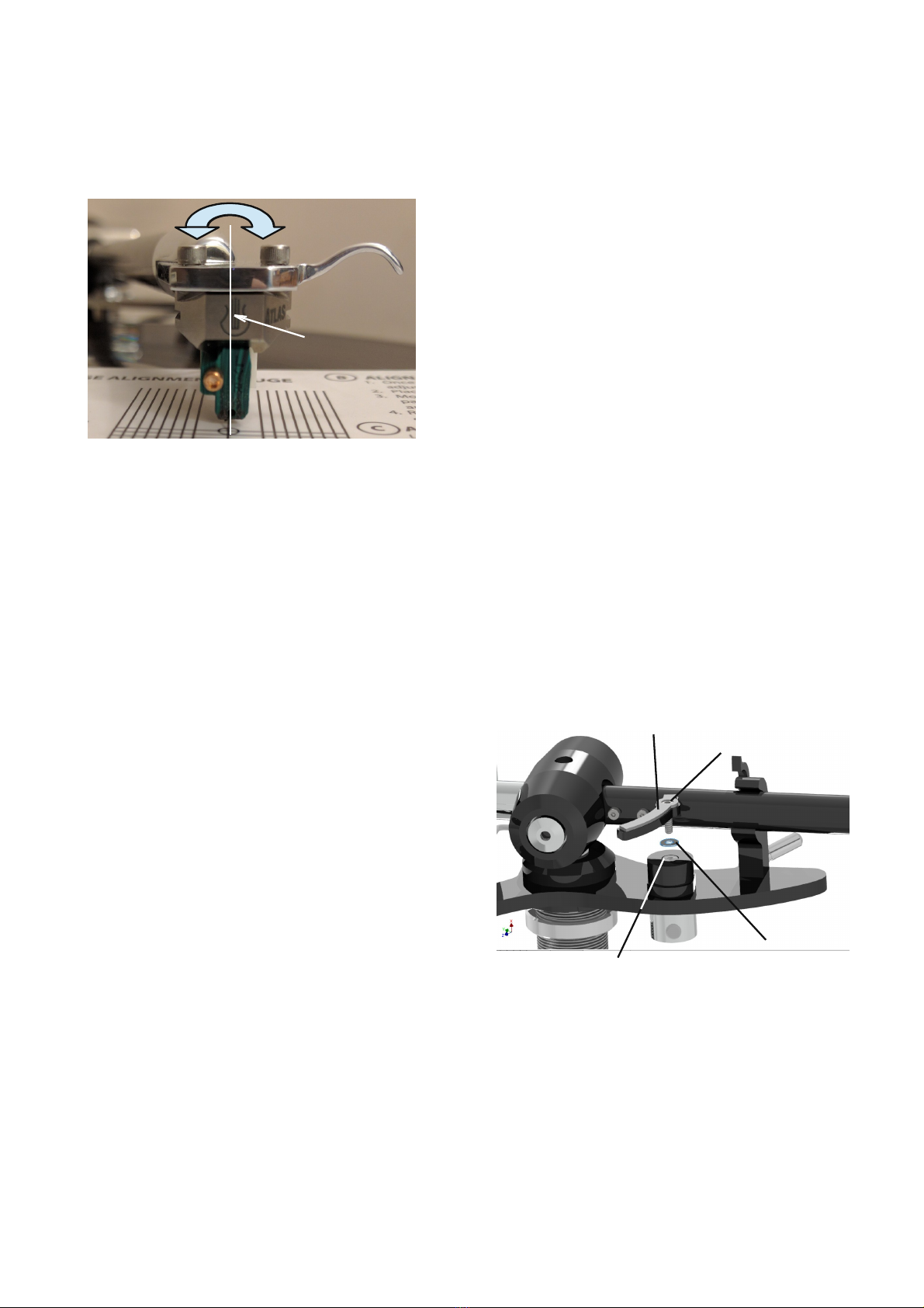
Cartridge alignment tools
Tools required are an alignment gauge, a ruler, a tracking
force gauge, a FLAT record, a screwdriver or Allen keys
of the right size (usually 2mm , a good light may also be
helpful. Small needle-nose pliers and a magnifying glass
all help. A good “test record” such as the Hi Fi News test
record is useful.
Bear in mind that the most severe “tracking ability” tests
are hopelessly unrealistic and nothing tracks properly on
them.
Treat the arm with care as some parts are fragile. To this
end ensure that tightening of any bolts is carried out
gently and without causing undue strain.
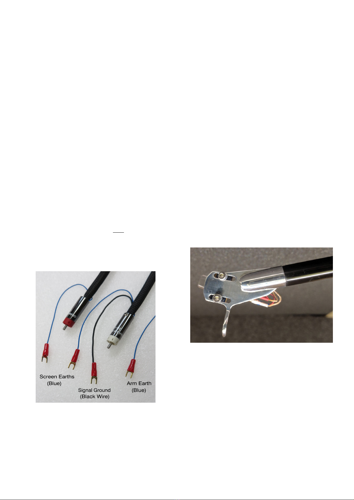
Tonearm wiring
Tonearm wiring uses a standard colour code for channel
and polarity identification: White = L Hot, Blue = L
Ground, Red = R Hot, and Green = R Ground. If the
cartridge pins aren’t colour-coded the same way, they
will have letter identifications next to them.
Cartridge tag conduction & fit
Low level signals are unbelievably sensitive, so good
conduction is essential and joints can be critical.
Make sure that the arm’s wires, wire clips, and solder
joints are in very good condition. At minimum, clean the
contact between cartridge pins and wire clips by
removing and replacing each clip. Holding the clips with
needle-nose pliers can make this easier, but be careful
that you don’t strain the wires where they join the clip.
Check the clips for a proper fit on the cartridge pins, and
adjust them if necessary. “Proper” means snug but not
tight. To check clip size, hold the cartridge tail-up close
to the head wires, grasp a clip firmly right behind its
tubular part with the tweezers, line it up with the
cartridge pin, and press. If it does not slide on with
moderate force, the clip needs opening-up. If it slides on
easily but flops around when attached, it needs
tightening. Re-sizing is the operation most likely to
detach a clip.
The trick is to avoid bending the wire at its attachment
point or putting too much tension on it. To avoid either,
always hold the clip with its wire slightly slack-looped
behind it while adjusting. For opening a clip, hold it
firmly with the tweezers or needle-noses, right behind its
tubular section, and press the tip of the jeweler’s
screwdriver into the open end of its longitudinal slot
until you see this widen very slightly. (Here’s where
you’ll probably need the magnifier or reading glasses. .
You’re dealing with thousandths of an inch here, so a
barely visible spreading may be all that’s needed.
Try it for fit, and repeat until it does. For tightening a
clip, press a toothpick inside it as far as it will go, then
use the needle-nose pliers to gently squeeze
together the sides of the clip near its free end, while
watching the slot for any change. (Attempting to
squeeze a clip without the toothpick inside it will
flatten its sides. Try it for size, and re-squeeze if
necessary until the fit is correct. When it is, close
up the middle section of the tube to match the end.
Static on Arm
Under certain conditions it's possible for severe
static charge to build up on the arm, which then
causes a noise when the finger lift is touched.
Dry climates or air conditioned environments are
the worst for this so remedies include:
•Place a pot plant in the room to get
moisture into the air.
•Wipe the arm with antistatic fluid such as
L'art du Son which leaves no residue ( do
not use furniture spray .
•Avoid Synthetic carpets and clothing.
RECORD & STYLUS CARE
Record and stylus care are big subjects well beyond
the brief scope of these instructions. To help on this
we've produced Youtube videos which can be found
on the Origin Live Youtube channel (use google to
find this .
CARE OF CARTRID ES
Suspension Aging
Replace your cartridge when due. Most hi-fi
cartridges have a lifespan for their cantilever
suspensions, which age even when not in use. This
will vary from manufacturer and type of cartridge
but 6 years is common.
Stylus Wear
Styli wear down due to record friction. Cleaning
records and stylus properly will dramatically
improve the life of both. It also increases
performance significantly.
Cleaning Strategies
There are a number of strategies for cleaning styli,
each with it's own merits. We recommend a
combination of the below. The items concerned are
available on the Origin Live website.
Small cartridge cleaning brush
These brushes are usually supplied with your
cartridge. If there is a build-up of dust and dirt
Page 10

where the needle enters the cartridge body you should
use a small soft brush to brush the debris out. Always
brush from the direction of the cantilever to the stylus or
you may do damage.
Passion dust Buster (use when visible
contamination is present)
This helps remove fluff and particle build up on the
stylus.
Cleaning fluid (use infrequently)
Lyra cleaning fluid or similar is helpful to dissolve
substance build up. Some fluids dissolve glue so
minimal quantity should be used on a cotton bud or
brush and only damp to prevent fluid running up the
cantilever by capillary action.
Green Stuff paper (use once a week or so)
This is a very fine abrasive paper that will not harm your
stylus but will remove baked on substances.
RECORD CARE AND
CLEANING
The stylus itself does a pretty good job of cleaning the
grooves and should itself therefore be kept very clean.
Proprietary brushes etc. for cleaning records will often
do little more than brush dirt deeper into the record
grooves and are best avoided if possible.
igh Quality Record Sleeves
Keep records in high quality non-scratch record sleeves -
preferably good ones.
Record Cleaning Machines
A record cleaning machine is really the only answer for
cleaning records properly as they suck out the debris and
dust in the record grooves using a powerful vacuum.
Tests using a microscope prove that this does the job
with 100% success. The performance improvement is
also very noticeable when it comes to even new records
being played. We offer a number of high grade cleaning
machines – see web site for details.
Cleaning Fluids
The most overlooked item in cleaning records is the
Cleaning fluid itself and there are many that fail to
do the job properly because they have not been
developed by trained chemists. For example, Iso-
propanol or detergent based cleaners may degrease
the record but damage it slowly as well.
We only recommend L'Art du Son cleaning fluid
which has consistently outperformed everything
else in reviews. Formulated by a trained Chemist
and leading turntable designer, this fluid will:.
•Reduce Static charge on the record surface
•Clean grease and other contaminates
•Not damage your records
•Leave no surface residue
ACKING FOR TRANSIT
If you need to send the arm anywhere the
following procedure must be followed carefully to
avoid damage to
Remove the counterweight from the rear stub and
wind the vta adjuster wheel up as high as possible.
Locate the armtube in the arm clip and fasten in
place using wire wrap as shown below.
Pack arm in original box or use a box with bubble
wrap or scrunched up newspaper.
Page 11
Origin Live Ltd, Unit 5, 362b Spring Road, Sholing, Southampton, SO19 2PB
www.originlive.com [email protected]
Wire wrap (food bag tie or similar)
Polythene bag
Other manuals for ALLIANCE
1
This manual suits for next models
3
Table of contents
Other Origin live Turntable manuals

Origin live
Origin live Calypso MKII User manual

Origin live
Origin live ENCOUNTER User manual

Origin live
Origin live Aurora Mk2 User manual

Origin live
Origin live The Complete Ultra Turntable kit User manual

Origin live
Origin live Aurora Mk3 User manual

Origin live
Origin live THE RESOLUTION CLASSIC User manual

Origin live
Origin live ALLIANCE User manual

Origin live
Origin live AURORA GOLD User manual

Origin live
Origin live Calypso MK3 User manual

Origin live
Origin live Aurora MK4 User manual