Origin live Aurora MK4 User manual

Aurora & Calypso MK4
Turntable Manual
Arm shown is not included
PLINTH
PLATTER
SUB-CHASSIS
MOTOR POD
It cannot be overstated that
it is VERY important to read
these instructions or the
speed control may not
function accurately.
IMPORTANT NOTES
Never remove the silver strip on underside of
platter.
Motor Pod blue light under platter must come
on when platter is driven. If not reposition
motor pod or raise deck till it does.
For Multi Layer platters - slacken screws as
per instructions.
Never stretch the belt e cept to place it over
the pulley. If you test stretch the belt you can
damage it resulting in future breakage

Introduction
Congratulations and thank you for choosing an Origin
Live turntable. This should give many years of
enjoyment, reliability and low maintenance.
It's critical that these instructions are read fully to
achieve best performance. Underlined te t is especially
important.
The instructions are written for owners with no previous
e perience, however there are aspects of the deck that
run contrary to e pectations, so e perts should not alter
anything without absorbing these instructions first.
Diagrams cover 3 different turntables so are for guidance
not e act representation.
Origin Live turntables are simple to set up. The
instructions appear lengthy because they give proper
e planation of factors that are different to conventional
set ups. If you have a problem not covered in the
instructions - you should speak to your dealer or refer to
technical support on the Origin Live web site
www.originlive.com - See top navigation bar “ support”.
There is a wealth of 3rd party information online.
YouTube videos are particularly helpful on how to set up
cartridges and tonearms should you need more help –
Just Google what you need to know.
Keep the turntable packing bo for secure future
transport.
Safety Warnings
Voltages inside the Motor Pod are dangerous so it must
not be opened.
Ensure Mains lead to the Motor Pod cannot be pierced
by spikes or similar abuse. Also ensure the lead cannot
cause anyone to trip.
Furthermore keep mains lead away
from areas where liquids could spill
on it.
Parts list
Plinth & Sub-chassis - including 1 cable clip with nut
& bolt.
Bag of parts
Cork washer for arm
Oil bottle
2.5mm allen key for arm clip
3mm Allen key
4mm Allen key
8mm A/F spanner – (12 inch arms only)
Platter
Upgrade platter mat
1 Belt + Spindle for platter + Strobe card
Motor pod
Owner manual, assembly sheet, Packing instructions
Set up & operation
Sub-chassis for 12 inch tonearms need to
be assembled to Plinth
Fit the 12 inch sub-chassis version to the deck as per
instruction sheet at the beginning of this booklet.
Note the above diagram is for guidance only – it's not an
e act representation.

Fit the Spindle
Oil the bearing
Run appro imately 17 drops of the oil supplied into the
top of the bearing house. The spindle will appear a loose
fit in the bearing house until the oil is added. Do not use
anything other than Origin Live oil for performance
reasons.
Insert the spindle
Inserting the spindle into the bearing house needs
attention as careless handling can damage the bearing
surfaces. Wipe the spindle surface first to ensure that it's
absolutely clean and very gently insert it into the bearing
house. If the oil does not overflow when the spindle
touches the bottom then try 2 more drops repeatedly till
you achieve overflow. Overflow can only be seen by
looking at the top of the bearing house with the spindle
inserted. You should notice an oil ridge around the
spindle – see diagram below.
Wipe away e cessive overflow at the top of the bearing
house but be careful to leave oil clinging to the spindle
as you need the top of the bearing to be lubricated by oil
overflow and things like tissue paper can suck this area
dry by capillary action. You should spin the spindle
slowly after it has settled into the bearing to ensure even
distribution of oil.
Note that when you oil the bearing, you can get a false
impression of overflow if the spindle has oil on it - the
oil simply scrapes off as the bearing slides in and ends
up on the top of the bearing house. You can “feel”
overflow when you insert the spindle and it meets
resistance at the bottom. This is not a “thud” of the
spindle hitting the bottom but rather a build up of
pressure as the bearing lands on a bed of oil. By further
pressing, you can then see the oil being squeezed out at
the top.
Notes on the bearing:
The bearing has significant play “rock” which runs
counter to e pectations. However, this feature achieves
very low friction levels. The spindle effectively rotates
on a thick film of oil without contacting the bearing
sides.
This means there is almost imperceptible platter
movement in rotation. Small low frequency deviations of
this nature are insignificant to performance and far
outweighed by the advantages of low friction and
reduced vibration.
All platters are rigorously checked for level spinning up
to 45rpm - if you notice significant platter flutter once
the belt is fitted, then remove the platter and clean taper
surfaces. Refit it till it sits true.
Do not spin the platter faster than 45rpm as the bearing
relies on a high precision oil film designed for optimal
sound quality within a specific speed range. At higher
than normal running speeds there will be slight platter
flutter.
Fit the Platter
Fit the platter gently over to the spindle but ensure the
tapered mating surfaces are absolutely clean before
assembly by wiping with tissue paper.
For Multi-Layer platter if included
Holding the Multi-layer platter
The top thin layers of the multi-layer platter are fragile
so do not hold the weight of the platter using the top
layers – also avoid placing the platter upside down on
surfaces as the spindle is fastened to a relatively fragile
material.
Slac en screws in the Multilayer Platter by 2/3rds
of a turn
The screws are tightened for transit to keep all layers
concentric with one another. However once you have
mounted the multi-layer platter, slacken all the white
nylon screws in the top of the platter anti-clockwise by
2/3 rds of a turn. This step is essential to allow the multi-
layer platter to perform as intended and makes a big
difference.
Fit Platter Mat
Finally add the platter mat ensuring the printed logo is
uppermost for sound quality reasons.
Adjust dec feet
No foot should be tightened fully onto the plinth as
performance is best when the foot sits on the thread
alone.
REAR METAL THREADED
FOOT
PLASTIC THREADED FEET
CABLE CLIP

Set the plinth height by rotating the 3 adjustable
feet. It helps to lift the dec slightly for access to
each foot in turn.Set the Platter Height
To set the plinth height correctly, place the motor pod
just beside the platter as shown above.
Set plinth height using the adjustable
feet, to give the platter 4 mm to 7mm
clearance between the top of the motor
pod and the underside of the platter as
shown below.
Level the dec using platter as reference
For accurate levelling place a bubble gauge on the
platter. Now adjust the feet till the armboard is level.
Position motor pod & fit belt
Power up
Plug the Motor Pod directly into a mains plug. We
suggest omitting mains conditioners, filters or anything
with surge protection as these can be highly detrimental
for performance. The aforementioned items inflict no
damage so you can e periment with their inclusion if
you wish.
Ensure items such as power amps or power supplies with
strong electromagnetic fields are kept away from the
motor pod (i.e not directly underneath or alongside).
Motor Pod position
Move the pod into position as shown below. The pod and
pod cable should not touch the plinth so rotate the pod if
necessary. Check the pulley to platter distance is initially
217mm or slightly more.
Fit the belt over the platter first and then pull it over the
motor pulley taking care not to twist it.
To set belt tension, simply move the pod.
As a rough guide, centre of platter spindle to centre of
motor pulley should be between 217 - 227mm. Note -
Low belt tension can result in slight platter flutter but for
a new belt start at 217mm.
The belt initially stretches slightly during the first hours
of use so leave final tension adjustment till 48 hours
have passed.Final positioning of motor pod
To set correct belt tension finally, lift the belt off the
pulley and let it lose it’s tension almost completely
whilst still holding it gently - With no tension
whatsoever in the belt it should be appro 7mm off the
nearside of the motor pulley (flange edge) as per
diagram below. Move the pod till the pulley is this
distance from the belt, then stretch the belt to fit over the
pulley.
Chec belt rides correctly
Rotate the platter by hand for a couple of turns and
check that the belt still sits between the 2 flanges of the
pulley. If this is not the case and it has ridden up onto a
flange push the belt back onto the crown (Curved portion
between the flanges) and turn the platter. Check the belt
remains on the crown.

People sometimes comment that the plastic pulley looks
cheap - However it's made from a special plastic which
sounds better than metal and is significantly more
e pensive to machine.
Note that belt grip varies according to the way it's fitted.
This means the deck will sound slightly different if you
refit the belt inside out or upside down from previously.
Therefore when removing and refitting the belt take care
to replace it with the same side in contact with the
running surfaces.
Position the Motor Pod correctly
The speed is controlled very accurately by a light sensor
reading the speed of the platter. You will notice 3 closely
spaced holes near the edge of the motor pod. These holes
house the light emitters and sensors that read platter
speed and must be positioned under the rim of the platter
as shown in photo below.
The sensor reads the silver strip on the underside of the
platter (see below). This strip must never be removed or
the speed will not be correct.
There are 2 blue LEDs which can light up (the other 2
never do as they are sensors). The blue LED nearest the
switch knob remains lit permanently when the power is
connected. The second blue light directly below the
platter, only comes on when the platter is rotating and
shows that the speed is correct. We call this the “speed
sensor light”
When the platter is rotating you should always see the
blue speed sensor LED below the platter, light up
( shown in the rectangle outline shown in preceding
illustration.)
Never disturb, poke or press any LEDs as it will wreck
speed reading.
Note that only the LED ne t to the knob lights up at this
stage and will remain on to show item is connected to
the mains.
Set up for Light speed control
Check that there is at least 5mm of clearance between
the top of the pod and the platter or the light sensor may
not work.
Switch on the speed to 33 rpm by turning the knob
clockwise one click. The deck should start and the blue
sensor light appear shining through the platter.
If the sensor light does not appear then switch off and
raise the deck by 1mm. This increases the gap between
the top of the Motor Pod and the Platter. Switch on again
and the blue light should appear. If not, repeat the
aforementioned process. The blue sensor light should
only shine when the platter is rotating correctly. It turns
off when the switch is turned off or the pod is not
positioned correctly.
Once the Blue light is functioning correctly, it’s
important to raise the plinth at least another 0.5mm to
ensure that the blue light is not in a “borderline”
condition leading to inaccurate control or turn off at a
later date.
The other factor that may prevent the blue sensor light
from lighting up is if the pod is positioned with the 3
LED holes not underneath the rim of the platter. Ensure
this is not the case.
Initially motors may be a little noisy but soon settle
down within a couple of days continuous running. The
sound quality also improves substantially after 40 hours
of running in.
Fine Tuning Motor screws
It should not be necessary but you can fine tune the
motor mount to give minimum noise by adjusting the
tightness of the 3 screws ne t to the motor pulley for
minimal tension - “just nipped” on the small rubber O
ring. Always check that the motor pulley is
appro imately vertical and that the belt runs clear above
the bottom flange as per earlier diagram.
Motor “running in” should be carried out with platter
turning (no faster than 45rpm).

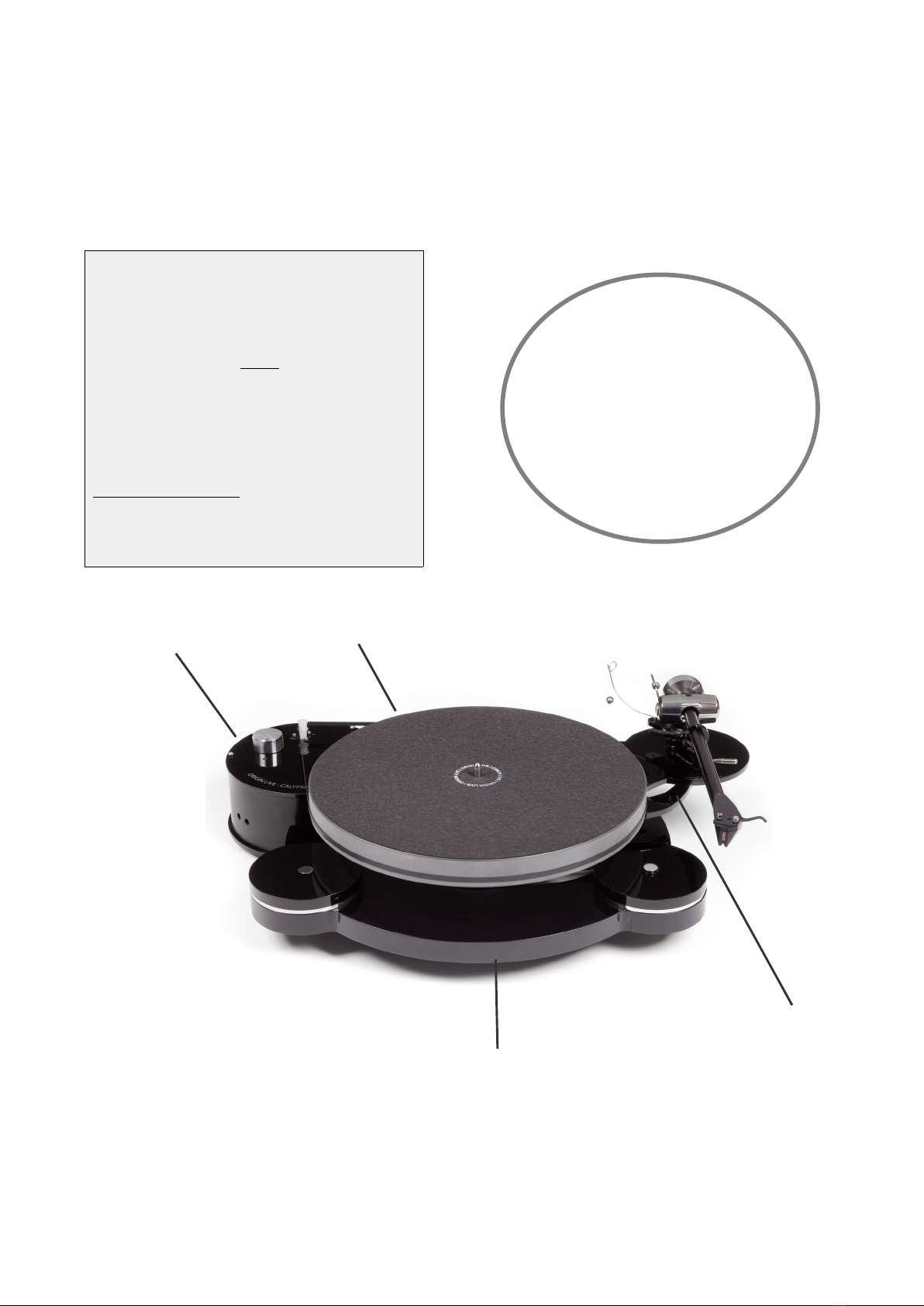
Control nob operation
The motor is “off” when the speed control knob on the
pod is turned fully anti-clockwise and the indent on the
knob aligns to the reference point.
Turn the knob one click clockwise to turn the motor on
at 33.3 rpm - The second click clockwise is 45rpm
Operating the strobe
You can check the speed of your deck by placing the
strobe disc on the record to be played. The strobe rings
are labelled on the centre of the disc for speed and mains
frequency.
Use correct lighting
The strobe effect shows best in fluorescent light,
although an ordinary bulb held about 2 feet from the
strobe disc will also work fine. The bulb flickers at 50
Hz in the EEC and 60 Hz in the USA.
You can purchase bayonet fitting fluorescent or halogen
bulbs to fit normal lamps. Try to shut out daylight when
carrying out speed reading. Also be aware that energy
saving lighting with switch mode high frequency power
supplies or certain energy saving bulbs will not work
with the strobe disc.
Reading the strobe
As you play the record. watch the relevant ring on the
strobe disc. Read the speed as described in ne t sub-
heading until marks on the ring concerned appear
stationary. It sometimes helps to stare the strobe but
focus your eyes on infinity.
Alternative methods
There are other strobes which are easier to read such as
the KAB strobe which can be found on our web site
under vinyl measurement accessories.
There is also a phone app that you can download for
Android or IOS. You simply then place the phone on the
platter and it reads the speed (but not very reliably).
Best results are achieved with the phone close to the
centre of the platter and ideally it should be supported
over the centre spindle of the platter.
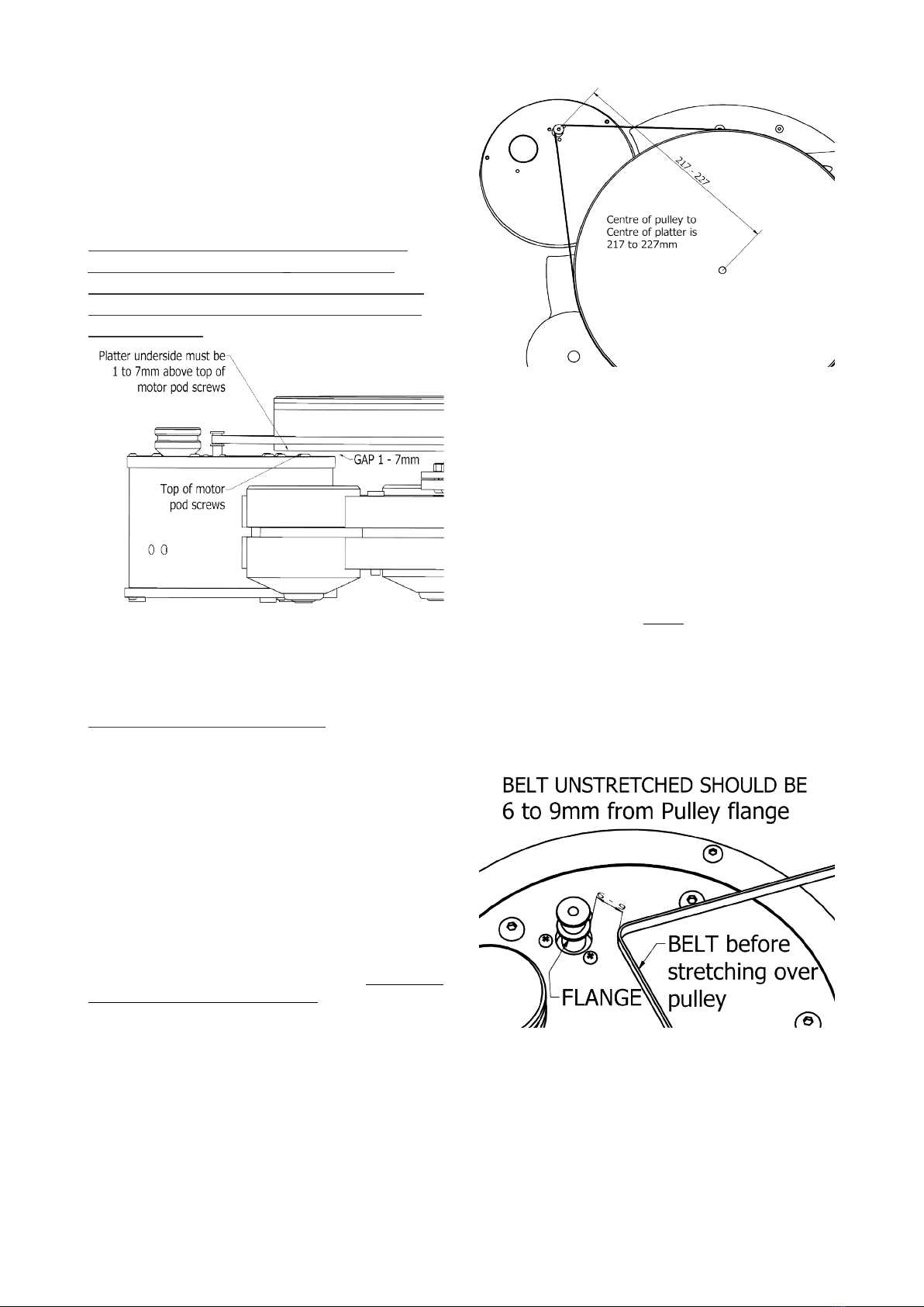
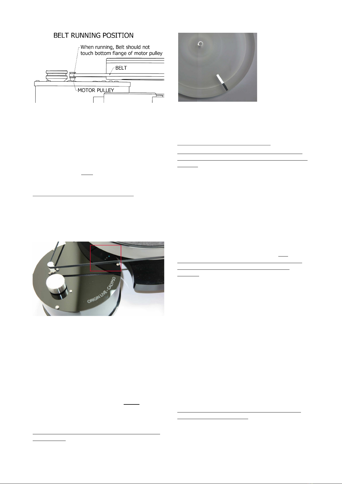
Notes on Belt & Motor running
Motor Tilt
Check that the belt rides clear of the flanges – nearly
touching is OK but if the belt sinks down to touch the
flange you need to either increase belt tension slightly or
adjust the tilt of the motor by turning the small cross-
head motor mounting screw positioned nearest the
platter.
Motor Noise
DC motors are often slightly noisy initially and never
completely silent in comparison to a/c motors. This may
be due in part to the high conductivity precious metal
brushes. These produce much lower levels of vibration
and hence better performance.
Like most turntable manufacturers we recommend you
leave the turntable running between changing records as
this reduces belt wear due to constant stopping and
starting.
Why measurements can be misleading
The figures on speed accuracy of the deck are well ahead
of industry standards however it's worth mentioning that
the Fleikhart measurement system is now well reported
on the web to be inaccurate due to off-centre discs and
poorly recorded tone. It has currently been withdrawn
from production.
Similarly Mobile phone apps are only a rough guide.
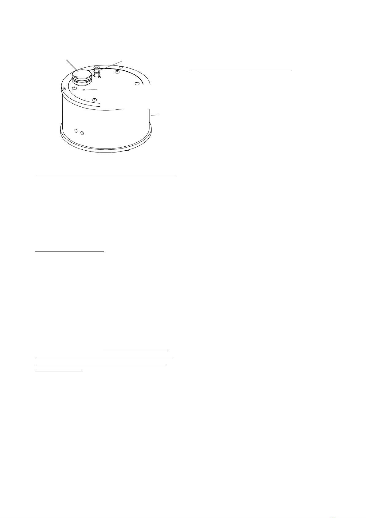
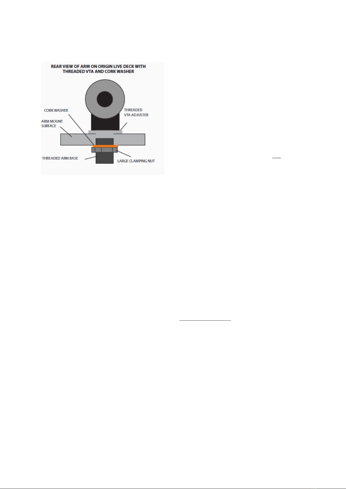
Fit the tonearm
Mounting Origin Live arms
All newer Origin Live arms have built in VTA
adjustment and can be fitted directly to the arm board as
illustrated below.
If you have an older Origin Live or Rega tone-arm which
has a threaded base but no vta adjustment, you can fit a
threaded VTA adjuster. The adjuster must be threaded
onto the base of the arm first and oriented such that the
flange is uppermost.
Insert your arm through the hole in the arm board.
Ne t fit the cork washer followed by the large clamping
nut as shown in the diagram on this page.
Lastly fit the tone-arm cables through the cable clip on
the underside of the deck. This improves performance
slightly and safeguards the cables from stressing their
joint at the arm base in the event of being “tugged”. The
cables should not be tight but form a gentle loop.
If clamping the cable is undesirable you can omit this
step.
MOTOR POD
PULLEY
POWER
INPUT
SWITCH REFERENCE
POINT
SPEED CONTROL
KNOB

We will cover setting the arm to e actly the correct
height later as you need to do a number of other things
first.
Final setup of tonearm
You should refer to your tone-arm instructions for
detailed set up of the arm and cartridge alignment.
Fit the arm cable clip
Pass the arm cable through the cable clip supplied and
fasten in position with the M5 bolt located in the
threaded hole near the rear foot. Leave a slight droop on
the cable so that it isn’t “tight”. The bolt is helpful to
minimize cable vibration.
Note – Silver Hybrid cable is relatively thick but both
left and right channels will fit trough one of the cable
clips supplied.
Maintaining your deck
Cleaning
To avoid belt vibration or wow & Flutter, it aids
performance to clean all running surfaces every 3
months with mentholated or surgical spirit. Wiping (not
dipping) with Acetone (Nail Varnish remover) is an
alternative, as is iso-propanol.
Belts can also be cleaned with soap & water then rinsed
thoroughly. Rubber care products can leave behind a
slippery residue.
To clean the deck, use a damp soft lint free cloth and
wipe gently – if you have grease marks etc then you can
use a general-purpose anti-smear, car window cleaner
such as Auto-glym “Fast glass”, but only if necessary.
Wa furniture polish is to be avoided . Do not spray
directly on the turntable as it may clog up the cartridge
internals etc but rather spray onto a soft polishing cloth
and then use it on the turntable. Do not use tissue paper
or kitchen cleaning paper towels as paper is abrasive and
can put faint scratches in the polished surface.
Scratch removal
If minor abrasions occur on the surface, you can remove
them using a proper plastic scratch remover polish such
as “Xerapol” by E.V.I of Germany or “Plastic Clean &
Shine by Novus inc of USA. Avoid Car and other
polishes as they leave light scratching or bloom.
Every 2 Years or so
The deck is not prone to going out of tune:
Check that the sub-chassis curved damper is
tensioned lightly onto the plate every 2 years or so as the
damper can compress a little over time.
Check belt tensi n is correct using the method
described for final pod positioning. All belts stretch over
the years so the motor pod may need to be moved out
further than the initially specified 227mm ma imum.
Depending on your use of the deck, the belt should
ideally be replaced every 2 to 4 years.
Every 3 years
Only use Origin Live oil. Oil should be replaced every 3
to 4 years so you will need to clean out the old oil with a
lint free paper towel or similar wrapped around a thin
rod. When you do this, be sure to also wipe oil off the
spindle as this may contain microscopic contamination
that's not visible.
If you ever withdraw the main spindle you should put a
few drops of oil into the bearing house to compensate for
any possible loss occuring in the withdrawal.
Never tamper with the bolt in the bottom of the bearing
or oil leaks will occur and you will probably not succeed
in re-tightening it.
Alternative Mats?
Many of the mats on the market have been tried on our
platters and do not work better than our own award
winning mat (included with this turntable) so we
recommend saving yourself the e pense of trying them.
Troubleshooting
Refer to the Origin Live website > Support > Technical
Support > Turntables if you have any problems.

Wrap motor pod in polythene bag then tape ( or
rubber band) round the cardboard tube which has
a slit in it’s side - the tube sits on top of the base
plate, not round it. This is to provide protection
against anything that might knock the end of the
motor shaft as this can cause damage. Note that
the motor pod must be positioned in this corner
of the bo where there is the greatest depth i.e
not over the plinth armboard
Place the strobe card and belt in the top of the
motor pod card tube.
WRAP PLINTH IN POLYTHENE BAG BEFORE
LOWERING INTO BOX
VERY IMPORTANT -
This card and foam peice
must be placed here as
shown to protect platter
and ensure no damage to
sub-chasses
BELT & STROBE CARD PLACED IN MOTOR
POD PACKING
The belt needs to be rolled into a spiral and
placed in a small polythene bag - if loose packed
the belt can get crushed on bends and
permanently deformed.
REPACKING METHOD - Please read carefully and pack exactly as
instructions show.
Place the wall wart transformer here and then place
the bubble bag containing the following items on top
of the transformer
Wrap platter and platter
mat in polythene bag
before placing in foam
cut out
Instruction manual
Bag contains - Cork washer for arm, Oil bottle,
screw driver, 3mm & 2.5mm allen key
This manual suits for next models
1
Table of contents
Other Origin live Turntable manuals

Origin live
Origin live Turntable kit ALL VERSIONS User manual

Origin live
Origin live AURORA GOLD User manual

Origin live
Origin live ENCOUNTER User manual

Origin live
Origin live Aurora Mk2 User manual

Origin live
Origin live Calypso MKII User manual

Origin live
Origin live Aurora Mk3 User manual

Origin live
Origin live THE RESOLUTION CLASSIC User manual

Origin live
Origin live Calypso MK3 User manual

Origin live
Origin live ALLIANCE User manual

Origin live
Origin live The Complete Ultra Turntable kit User manual