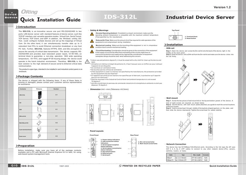
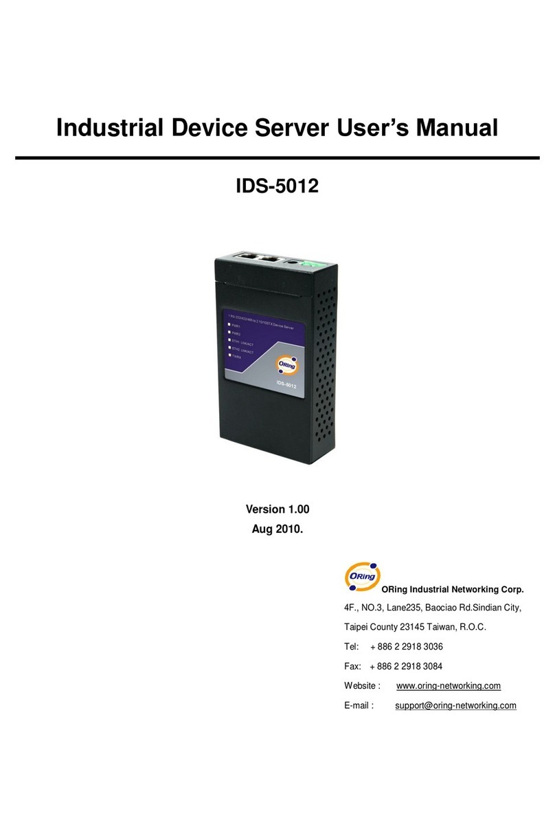
ORiNG IDS-1112 User manual

I
ID
DS
S-
-1
11
11
12
2
I
In
nd
du
us
st
tr
ri
ia
al
l
W
Wi
ir
re
el
le
es
ss
s
D
De
ev
vi
ic
ce
e
S
Se
er
rv
ve
er
r
U
Us
se
er
r’
’s
s
M
Ma
an
nu
ua
al
l
V
Ve
er
rs
si
io
on
n
1
1.
.0
0
A
Ap
pr
r,
,
2
20
01
13
3
w
ww
ww
w.
.o
or
ri
in
ng
g-
-n
ne
et
tw
wo
or
rk
ki
in
ng
g.
.c
co
om
m

ORing Industrial Networking Corp.
COPYRIGHT NOTICE
Copyright © 2011 ORing Industrial Networking Corp.
All rights reserved.
No part of this publication may be reproduced in any form without the prior written consent of
ORing Industrial Networking Corp.
TRADEMARKS
is a registered trademark of ORing Industrial Networking Corp.
All other trademarks belong to their respective owners.
REGULATORY COMPLIANCE STATEMENT
Product(s) associated with this publication complies/comply with all applicable regulations.
Please refer to the Technical Specifications section for more details.
WARRANTY
ORing warrants that all ORing products are free from defects in material and workmanship for
a specified warranty period from the invoice date (5 years for most products). ORing will repair
or replace products found by ORing to be defective within this warranty period, with shipment
expenses apportioned by ORing and the distributor. This warranty does not cover product
modifications or repairs done by persons other than ORing-approved personnel, and this
warranty does not apply to ORing products that are misused, abused, improperly installed, or
damaged by accidents.
Please refer to the Technical Specifications section for the actual warranty period(s) of the
product(s) associated with this publication.
DISCLAIMER
Information in this publication is intended to be accurate. ORing shall not be responsible for its
use or infringements on third-parties as a result of its use. There may occasionally be
unintentional errors on this publication. ORing reserves the right to revise the contents of this
publication without notice.
CONTACT INFORMATION
ORing Industrial Networking Corp.
3F., No.542-2, Zhongzheng Rd., Xindian Dist., New Taipei City 23148, Taiwan (R.O.C.)
Tel: +886-2-2218-1066 // Fax: +886-2-2218-1014
Website: www.oring-networking.com
Technical Support
E-mail: support@oring-networking.com
Sales Contact
E-mail: sales@oring-networking.com (Headquarters)
sales@oring-networking.com.cn (China)

Tables of Content
Getting to Know your Wireless Media Gateway......................................... 1
1.1 ..............................................................................................................................1Overview
1.2 ..............................................................................................................1Software Features
1.3 .............................................................................................................2Hardware Features
Hardware Installation.................................................................................... 3
2.1 ..........................................................................3Installation Media Gateway on DIN-Rail
2.2 ..................................................................................................4Wall Mounting Installation
Hardware Overview....................................................................................... 6
3.1 ..........................................................................................................................6Front Panel
3.2 ...............................................................................................................7Front Panel LEDs
3.3 .......................................................................................................................8Bottom Panel
3.4 ...........................................................................................................................8Rear Panel
Cables and Antenna...................................................................................... 9
4.1 ..................................................................................................................9Ethernet Cables
4.2 ..............................................................................................................10Wireless Antenna
Management Interface.................................................................................11
5.1 ........................................................................................................11First-time Installation
5.2 Configure the Wireless Media Gateway.....................................錯誤! 尚未定義書籤。
5.3 ....................................................................................................................12Main Interface
5.3.1 ...................................................................................................................12Basic Setting
WAN.........................................................................................................................................12
LAN .........................................................................................................................................13
DHCP.......................................................................................................................................14
Wireless....................................................................................................................................16
5.3.2 ............................................................................................................21Advanced Setting
Wireless....................................................................................................................................27
NAT Setting..............................................................................................................................30
Security Setting........................................................................................................................34
VPN Setting .............................................................................................................................35
Routing Protocol (Routing Setting)..........................................................................................43
Notification ..............................................................................................................................44
Miscellaneous (DDNS)............................................................................................................47
5.3.3 ...................................................................................................................47System Tools

ORing Industrial Networking Corp.
Date & Time.............................................................................................................................47
Login Setting............................................................................................................................48
Media Gateway Restart............................................................................................................50
Firmware Upgrade ...................................................................................................................50
Save/Restore Configurations....................................................................................................51
Miscellaneous (Ping)................................................................................................................51
5.3.4 ..................................................................................................................52System Status
System Info ..............................................................................................................................52
System Log ..............................................................................................................................52
Traffic Statistics........................................................................................................................53
Wired/Wireless Clients..........................................................................錯誤! 尚未定義書籤。
Technical Specifications .............................................................................54


IAR-120 / 120+ User’s Manual
Getting to Know your Wireless Media
Gateway
1.1 Overview
The ORing IMG-8042 is an innovative 4port
RS232/422/485 Serial Wireless Gateway. You can
conveniently manage the device by windows Tool
The Media Gateway provides a fast and effective
ways of communicating to the internet over wired
or wireless LAN. In addition, multiple kinds of
WAN connection are provided for easily access to
the internet.
The ORing IMG-1321-D wireless Media
Gateway is with IEEE 802.11a/b/g or IEEE
802.11b/g high-performance wireless equipment. It is capable of data transfer rates up to
54Mbps. It is easy for you to extend the reach and number of computers connected to
your wireless network.
With build-in HSUPA WAN connection, the ORing IMG-1321-D wireless Media Gateway
can be mounted in harsh environment easily to provide internet access anytime and
anywhere.
The ORing IMG-1321-D wireless Media Gateway's VPN capability creates encrypted
"Virtual Tunnels" through the internet, allowing remote or traveling users for secured
connection with the network in your office.
1.2 Software Features
Intuitive Web-based management user interface for simply and easily operation.
USB connectivity providing Internet access via the USB to RS232 convertor + modem
or 3G HSDPA module (HUAWEI E220) directly.
Functions of firewall provides many security features such as blocking attacks from
hacker, especially IP Spoofing, Ping flood, Ping of Death, DOS, DRDOS, Stealth Scan,
ICMP flooding etc.
Advanced firewall configuration to extend the capability and security, such as Virtual
ORing Industrial Networking Corp. 1

IMG-1312-D User’s Manual
Server, Port Trigger, DMZ host, UPnP auto Forwarding, IP Filter and MAC filter.
1.3 Hardware Features
Two 10/100Base-T(X) Ethernet ports for WAN / LAN connection individually.
Redundant Power Inputs: 12~48 VDC on terminal block
4 digital inputs/outputs on terminal block
Casing: IP-40
Dimensions(W x D x H) : 72(W)x29.4(D)x123.4(H) mm
Operating Temperature: -10 to 60oC
Storage Temperature: -40 to 85oC
Operating Humidity: 5% to 95%, non-condensing
O
RingIndustrialNetworkingCorp. 2

IMG-1312-D User’s Manual
Hardware Installation
2.1 Installation Media Gateway on DIN-Rail
Each Wireless Media Gateway has a DIN-Rail kit on rear panel. The DIN-Rail kit helps
Media Gateway to fix on the DIN-Rail.
Step 1: Slant the Media Gateway and mount the metal spring to DIN-Rail.
Metal
Spring
Step 2: Push the Media Gateway toward the DIN-Rail until you heard a “click” sound.
ORing Industrial Networking Corp……………………………………………………………….…3

IMG-1312-D User’s Manual
2.2 Wall Mounting Installation
Each Media Gateway has another installation method to fix the Media Gateway. A wall
mount panel can be found in the package. The following steps show how to mount the
Media Gateway on the wall:
Step 1: Remove DIN-Rail kit.
Step 2: Use 6 screws that can be found in the package to combine the wall mount panel.
Just like the picture shows below:
O
RingIndustrialNetworkingCorp. 4

IMG-1312-D User’s Manual
The screws specification shows in the following two pictures. In order to prevent the
Media Gateways from any damage, the screws should not larger than the size that used in
IMG-1312-D.
Pozidrive
ORing Industrial Networking Corp……………………………………………………………….…5

IMG-1312-D User’s Manual
Hardware Overview
3.1 Front Panel
1
4
2 7
9
11
10
8
6
3
5
12
1. 850/900/1800/2100MHz antenna for internal HSUPA modem
2. HSUPA Cellular Modem with SIM card slot
3. WLAN signal strength indicator, WLAN Strength: 1<25% , 2<50%, 3<75%,
4<100%
4. RS-232 serial port.
5. WLAN Antenna
6. WLAN LED indicator, light up after the wireless is enable.
7. LED for PWR1 and system status. When the PWR1 links, the green LED will be
light on.
8. LED for PWR2 and system status. When the PWR2 links, the green LED will be
O
RingIndustrialNetworkingCorp. 6

IMG-1312-D User’s Manual
light on
9. LED for fault indicator. When fault occurred, this red LED will be light on.
10. LED for HSUPA modem connection.
11. LED of serial port. Green for transmitting, red for receiving
12. 10/100Base-T(X) Ethernet port
3.2 Front Panel LEDs
The following table describes the labels that stick on the IMG-1312-D.
LED Color Status Description
On WLAN activated.
WLAN Green Blinking WLAN Data transmitted.
Green On DC power 1 activated.
PWR1 Green / Red Green blinking Device booting
Green On DC power 2 activated.
PWR2 Green / Red Green blinking Device booting
Amber On Fault relay. Power failure or
Port link down.
WLAN
Strength Green On
WLAN signal strength.
1<25%, 2<50%, 3<75%,
4<100%
Green On Modem Ready
Green Blinking Serial port is transmitting data
Serial Red Blinking Serial port is receiving data
Green On/Blinking 100Mbps LNK/ACT
ETH 1/2 Green/Amber Amber On/Blinking 10Mbps LNK/ACT
ORing Industrial Networking Corp……………………………………………………………….…7

IMG-1312-D User’s Manual
O
RingIndustrialNetworkingCorp. 8
3.3 Bottom Panel
The bottom panel components of IMG-1312-D are shown as below:
3.4 Rear Panel
The rear panel components of IMG-1312-D are shown as below:
1.Screw holes for wall mount kit.
2.DIN-Rail kit
12

IMG-1312-D User’s Manual
Cables and Antenna
4.1 Ethernet Cables
The IMG-1312-D Media Gateways have standard Ethernet ports. According to the link
type, the Media Gateways use CAT 3, 4, 5, 5e UTP cables to connect to any other network
device (PCs, servers, switches, Media Gateways, or hubs). Please refer to the following
table for cable specifications.
Cable Types and Specifications
Cable Type Max. Length Connector
10BASE-T Cat. 3, 4, 5 100-ohm UTP 100 m (328 ft) RJ-45
100BASE-TX Cat. 5 100-ohm UTP UTP 100 m (328 ft) RJ-45
100BASE-TX/10BASE-T Pin Assignments
With 100BASE-TX/10BASE-T cable, pins 1 and 2 are used for transmitting data, and
pins 3 and 6 are used for receiving data.
RJ-45 Pin Assignments
ORing Industrial Networking Corp……………………………………………………………….…9

IMG-1312-D User’s Manual
Pin Number Assignment
1 TD+
2 TD-
3 RD+
4 Not used
5 Not used
6 RD-
7 Not used
8 Not used
The IMG-1312-D Media Gateways support auto MDI/MDI-X operation. You can use a
straight-through cable to connect PC and Media Gateway. The following table below
shows the 10BASE-T/ 100BASE-TX MDI and MDI-X port pin outs.
MDI/MDI-X pins assignment
Pin Number MDI port MDI-X port
1 TD+(transmit) RD+(receive)
2 TD-(transmit) RD-(receive)
3 RD+(receive) TD+(transmit)
4 Not used Not used
5 Not used Not used
6 RD-(receive) TD-(transmit)
7 Not used Not used
8 Not used Not used
Note: “+” and “-” signs represent the polarity of the wires that make up each wire pair.
4.2 Wireless Antenna
A 2.4GHz antenna is used for IMG-1312-D and connected with a reversed SMA connector.
External antenna also can be applied with this connector.
O
RingIndustrialNetworkingCorp. 10

IMG-1312-D User’s Manual
Management Interface
5.1 First-time Installation
Before installing IMG-1312-D WLAN Media Gateway, you need to access the WLAN
Media Gateway by a computer equipped with an Ethernet card or wireless LAN interface.
Using an Ethernet card to connect to LAN port is easier and recommended.
Step 1: Select the Power Source
IMG-1312-D Media Gateway can be powered by +12~48V DC power input, or by P.O.E.
(Power over Ethernet) PSE Ethernet switch.
Step 2: Connect a computer to IMG-1312-D
Use either a straight-through Ethernet cable or cross-over cable to connect to ETH1 of
IMG-1312-D Media Gateway to a computer. If the LED of the LAN port lights up, it
indicates the connection is established. After that, the computer will initiate a DHCP
request to get an IP address from the Media Gateway.
Step 3: Use the web-based manager to configure IMG-1312-D
The default gateway IP of IMG-1312-D Media Gateway is 192.168.10.1. Start the web
browser of your computer and type http://192.168.10.1 in the address box to access the
webpage. A login window will popup, and then enter the default login name admin and
password admin.
Login
ORing Industrial Networking Corp……………………………………………………………….…11

IMG-1312-D User’s Manual
5.2 Main Interface
The Home will be shown when login successfully.
Main Interface
In the page, you can check the Firmware version, the Media Gateway up time and the
WAN IP setting.
The following table describes the labels in this .
Label Description
Firmware Show the current firmware version.
Uptime Show the elapsed time since the Media Gateway is started.
Wan IP Show the WAN IP address.
5.3.1 Basic Setting
WAN
The IMG-1312-D Media Gateway provide 3G WAN connection.
O
RingIndustrialNetworkingCorp. 12

IMG-1312-D User’s Manual
.
Modem/3G
The following table describes the labels in this .
Label Description
Phone Number Telephone number provided by your ISP.
APN Enter the APN value it is optional
User Name User name provided by your ISP.
Password Password provided by your ISP.
PIN Enter the PIN code if PIN check is required.
Auto Connect If this option is enabled, the connection will be called up when
Media Gateway boots up.
Device Status Show the status of Medem/3G device.
Operations Click “Connect” to call up the Modem/3G. Click "Disconnect" to
shut down the connection.
Link Status Show the status of connection, up, down or connecting.
LAN These are the IP settings of the LAN interface for the IMG-1312-D WLAN
ORing Industrial Networking Corp……………………………………………………………….…13

IMG-1312-D User’s Manual
Media Gateway. The LAN IP address is privately for your internal network and
can not be exposed on the Internet.
LAN
The following table describes the labels in this .
Label Description
Device Name Enter a name for this device
IP Address The IP address of the LAN interface, the default IP address is
192.168.10.1
Subnet Mask The Subnet Mask of the LAN interface, the default Subnet mask
is 255.255.255.0
DHCP
DHCP stands for Dynamic Host Control Protocol. The IMG-1312-D Media
Gateway with a built-in DHCP server. The internal DHCP server will assign an IP
address to the computers (DHCP client) on the LAN automatically.
Set your computers to be DHCP clients by setting their TCP/IP settings to Obtain
an IP Address Automatically. The DHCP server will allocate an unused IP address
from the IP address pool to the requesting computer automatically.
1. DHCP Sever
O
RingIndustrialNetworkingCorp. 14

IMG-1312-D User’s Manual
DHCP Server
The following table describes the labels in this .
Label Description
DHCP Server Enable or Disable the DHCP Server. The default setting is
Enable
Starting IP The starting IP address of the IP range for the DHCP server
Ending IP The ending IP address of the IP range for the DHCP server
Lease Time The period of time for the IP to be leased. Enter the Lease time.
The default setting is 48 hours.
Local Domain Name Enter the local domain name of private network. It is optional.
DNS Server 1&2 Enter the DNS Server. It is optional.
WINS Server Enter the WINS Server. It is optional.
Current DHCP Client
Information
List of the computers on your network that are assigned an IP
address by internal DHCP server.
2. IP Allocation
The IP Allocation provides one-to-one mapping of MAC address to IP address.
When a computer with the MAC address requesting an IP from the IMG-1312-D Media
Gateway, it will be assigned with the IP address according to the mapping. You can
choose one from the client lists and add it to the mapping relationship.
ORing Industrial Networking Corp……………………………………………………………….…15
Other manuals for IDS-1112
1
Table of contents
Other ORiNG Server manuals
ORiNG
ORiNG IDS-342GT User manual
ORiNG
ORiNG IDS-5042-WG Series User manual
ORiNG
ORiNG IDS-5011F Series User manual

ORiNG
ORiNG IUSB-9000 Series User manual
ORiNG
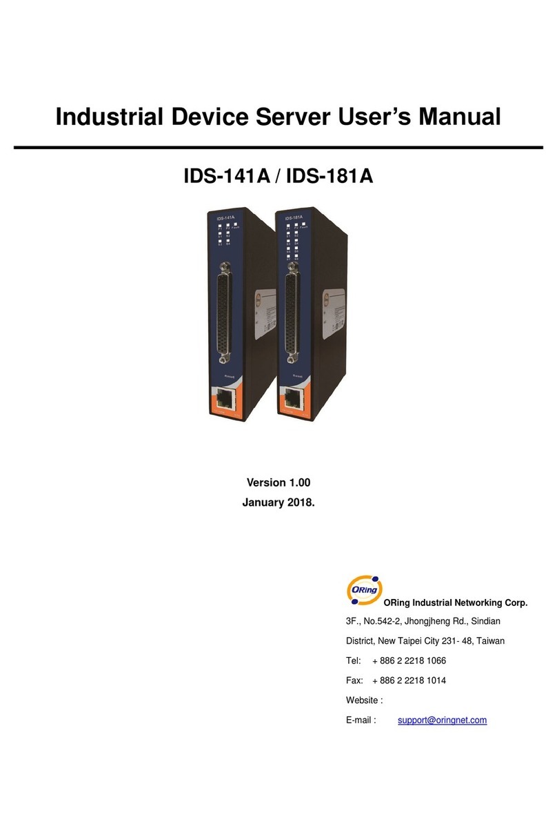
ORiNG IDS-181A User manual
ORiNG
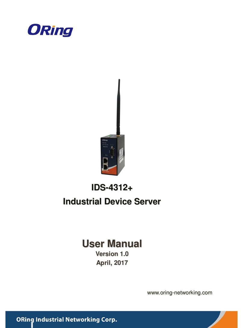
ORiNG IDS-4312+ User manual
ORiNG
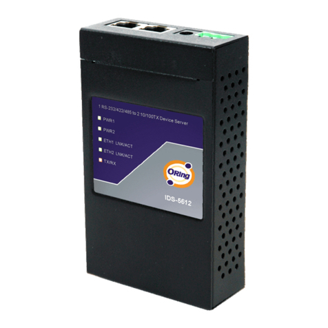
ORiNG IDS-5612 Series User manual
ORiNG
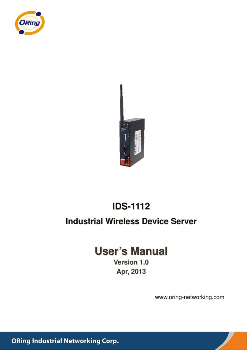
ORiNG IDS-1112 User manual
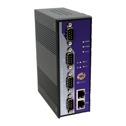
ORiNG
ORiNG IDS-5042 Series User manual
ORiNG
ORiNG IDS-342GT+ User manual
Popular Server manuals by other brands
Dell EMC
Dell EMC PowerEdge R340 Installation and service manual

Lenovo
Lenovo ThinkSystem SR670 reference guide

Digital Equipment
Digital Equipment Prioris HX590 DP Service maintenance manual

HP
HP ProLiant DL145 Maintenance and service guide

NEC
NEC Express5800/320Fd-LR user guide
Dell
Dell PowerEdge T710 Information update
