PWR-1PWR-2
V2+ V2- V1+ V1-
1A@24V
Q I G Quick Installation Guide
Quick Installation Guide
Version 2.2
Q I G
Cable Types and Specifications:
For pin assignments for different types of cables, please refer to the following
tables.
10/100 Base-T(X) MDI/MDI-X
Pin Number MDI port MDI-X port
1 TD+(transmit) RD+(receive)
2 TD-(transmit) RD-(receive)
3 RD+(receive) TD+(transmit)
4 Not used Not used
5 Not used Not used
6 RD-(receive) TD-(transmit)
7 Not used Not used
8 Not used Not used
Note: “+” and “-” signs represent the polarity of the wires that make up each
wire pair.
10/100 Base-T(X) RJ-45
Pin Number Assignment
1 TD+
2 TD-
3 RD+
4 Not used
5 Not used
6 RD-
7 Not used
8 Not used
Resetting
To reboot the switch, press the button for 2-3 seconds.Reset
To restore the switch configurations back to the factory defaults, press the button for 5 seconds.Reset
Wiring
The device has two sets of power inputs, power input 1
and power input 2. Follow the steps below to wire redundant
power
Power inputs
The two relay contacts on the terminal block allow you to form fail close circuits.
The relay contacts will respond to user-configured events according to the wiring.
Relay contact
Grounding and wire routing help limit the effects of noise due to electromagnetic
interference (EMI). Run the ground connection from the ground screws to the grounding
surface prior to connecting devices.
Grounding
Configurations
After installing the switch, the green power LED should turn on. Please refer to the
following tablet for LED indication.
1. Launch the Internet Explorer and type in IP address of the switch. The default static IP address is
192.168.10.1
2. Log in with default user name and password
(both are ). After logging in, you shouldadmin
see the following screen. For more information
on configurations, please refer to the user
manual. For information on operating the switch
using ORing’s Open-Vision management utility,
please go to ORing website.
Follow the steps to set up the card:
Specifications
Cable Type Max. Length Connector
10BASE-T Cat. 3, 4, 5 100-ohm UTP 100 m (328 ft) RJ-45
100BASE-TX Cat. 5 100-ohm UTP UTP 100 m (328 ft) RJ-45
STEP 1: Insert the negative/positive wires into the V-/V+ terminals, respectively.
STEP 2: To keep the wires from pulling loose, use a small flat-blade screwdriver
to tighten the wire-clamp screws on the front of the connector.
ORi ng Switch Mod el IES -2050A
10 /100 Ba se-T(X ) Port s in RJ45 Auto
MD I/MDI X
Phy sical Ports
5
Tec hnology
Et herne t Stand ards
IE EE 802. 3 for 10B ase-TX
IE EE 802. 3u for 10 0Base -TX
IE EE 802. 3x for Fl ow cont rol
IE EE 802. 1D for ST P (Span ning Tree Prot ocol)
IE EE 802. 1w for RS TP (Ra pid Spa nning Tree Protocol )
IE EE 802. 1AB for L LDP (Li nk Layer Disc over y Proto col)
Fau lt Contact
Relay Relay output to carry capacity of 1A a t 24 VDC
Pow er
Redund ant Inp ut powe r
Power co nsump tion( Typ. )
Du al DC inp uts, 12 ~48VD C on 6-pi n termi nal blo ck
Ov erloa d curre nt prot ectio n
Rever se pola rity pr otect ion
Pr esent
Pr esent o n termi nal blo ck
Phy sical Chara c teristic
En closu re IP-3 0 Metal ( non UL ce rtifi ed)
Di mensi on (W x D x H) 26 .1 mm (W) x 9 5 mm (D) x 14 4.3(H ) mm (1.0 3 x 3.74 x 5. 68 inch .)
Weig ht (g)
Env ironmenta l
-4 0 to 85 C (- 40 to 185 F)
o o
St orag e Temp erat ure
MA C Table 1K
≤4 Wa tts, 12 VDC/0 .29A (3 W), 24V DC/0. 14A (3W ), 48VD C/0.0 8A (4W)
* Su pplie d by SELV sou rce evaluat ed by UL 61 010-1 o r 61010 -2-20 1 power s upply o nly.
* Fourni p ar la sou rce SELV évalué e uniqu ement par l'alimen tation UL 6101 0-1 or 61 010-2 -201.
39 5 g
Pr iorit y Queue s 4
Pr ocess ing Sto re-an d-Forwar d
Sw itch Pr opert ies
Sw itchi ng late ncy: 8. 94 µs
Sw itchi ng band width : 1Gbps
Th rough put (pa cket pe r secon d): 76. 19Mpp s@64B ytes pa cket
VL AN: Po rt base d
Se curit y Features En able/ disab le port s,
VL AN to seg regat e and sec ure net work traffi c
So ftwar e Fea tures
ST P/RST P (IEEE 8 02.1D /w)
Redund ant Rin g (O-Ri ng) wit h recovery ti me less t han 10m s over 2 50uni ts
DH CP Clie nt
Port bas e VLAN
LL DP (Lin k Laye r Disco very P rotoc ol)
Port con figuratio n, stat us, sta tisti cs, mon itori ng, sec urity
SN MP v1/v 2c /v3 an d private MIB s uppor t
Ne twork Redun dancy
O- Ring
O- Chain
Fast r ecovery
RS TP/ST P
-4 0 to 75 C (- 40 to 167 F)
o o
Op erat ing Temperature
5% t o 95% Non -cond ensin gOp erat ing Hum idity
Reg ulatory App r ovals
CE E MC (EN 55 024, EN 5 5032, E N 61000 -6-2, E N 61000 -6-4) , FCC Pa rt 15 BEM C
EN 5 5024 (I EC/EN 6 1000- 4-2 (ES D: Cont act 4KV, Ai r 8KV), I EC/EN 6 1000- 4-3 (RS : 3V),
IE C/EN 61 000-4 -4 (EFT Power 0. 5KV, Sign al 0.5K V), IEC /EN 610 00-4- 5 (Surg e: Po wer 0.5 KV, RJ45 0. 5KV),
IE C/EN 61 000-4 -6 (CS: 3 V), IEC /EN 610 00-4- 8(PFM F), IEC /EN 61000-4-11 (DIP) )
EN 6 1000- 6-2 (IE C/EN 61 000-4 -2 (ESD : Conta ct 4KV, Air 8 KV), IE C/EN 61 000-4 -3 (RS: 1 0V),
IE C/EN 61 000-4 -4 (EFT Power 2K V, Signal 1 KV), IE C/EN 61 000-4 -5 (Sur ge: Power 0. 5KV),
IE C/EN 61 000-4 -6 (CS: 1 0V), IE C/EN 61 000-4 -8(PF MF), IE C/EN 61000-4-11 (DIP))
EM S
IE C6006 8-2-2 7Sh ock
IE C6006 8-2-3 1
IE C6006 8-2-6Vi brat ion
EN 6 0950- 1 (LVD)
Sa fety
Fr ee Fall
MTB F
17 96601 .9604 h rs
PRINTED ON RECYCLED PAPER
S W I T C H
I N D U S T R I A L
Industrial Lite-Managed Switch
DIP-Switch setting
P.F. Trigger alert when power fails (On: Enable, Off: Disable function)
R.E. Enable/Disable O-Ring function (On: Enable, Off: Disable)
R.M. Enable/Disable Ring Master Mode (On: Enable, Off: Disable)
R.S. Select O-Ring redundant port (On: ring port set to port-5 and port-6,
Off: ring port set to port-1 and port-2)
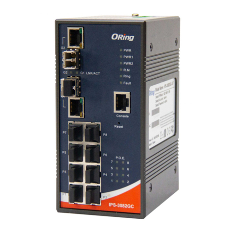
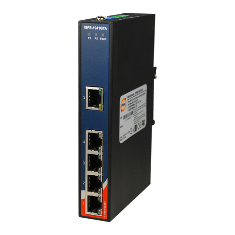
P1 Green On Power module 1 is activated
P2 Green On Power module 2 is activated
R.M Green On System running in Ring Master mode
Ring Green
On System running in Ring mode
Blinking Ring structure is broken (i.e. part of the
ring is disconnected)
Fault Amber On Faulty relay (power failure or port
malfunctioning)
10/100Base-T(X) Fast Ethernet ports
LNK
/ACT Green On Links are connected
Blinking Transmitting data
Duplex/
Collision Amber
On Full-duplex mode
Off Half-duplex mode
Blinking Half-duplex and collision occurred
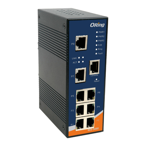
IES-2050A
IES-2050A
Packe t buffe r 1M bits
EN 5 5032, E N 61000 -6-4, C ISPR3 2, EN 610 00-3- 2, EN 610 00-3- 3, VCCI c lass A, F CC Par t 15 B clas s AEM I
War ranty
5 ye ars
ORing Industrial Networking Corp.
Copyright© 2015 ORing
All rights reserved.
TEL: +886-2-2218-1066
FAX: +886-2-2218-1014
Address 3F No 542 2 Zhongzheng Rd Xindian Dist New: ., . - , ., .,
Taipei City 23148 Taiwan,
Website: www.oringnet.com
E-mail: support@oringnet.com
Contact for maintenance and repair service:
!
Warning [AVERTISSEMENT]
Take into consideration the following guidelines before wiring the device
[Tenez compte des directrices suivantes avant de câbler l’appareil.]
1. Terminal block is mating with Plug and suitable for 12-24AWG.
Torque value 4.5 lb-in.
[Le bornier est compatible avec les connecteurs et convient pour 12-24AWG.
Valeur de couple 4,5 lb-in.]
2. The temperature rating of the input connection cable should higher than 105°C
[La température de service nominale du câble d’entrée doit être supérieure à 105 °C]
* Indoor use and pollution degree II, it must be wiped with a dry cloth for clean up the
device and label.
* Utilisation en intérieur et degré de pollution II, il faut l'essuyer avec un chiffon sec pour
nettoyer l'appareil et son étiquette.
* Do not block air ventilation holes.
* Ne bouchez pas les orifices de ventilation.
* If the equipment is used in a manner not specified by the manufacturer, the protection
provided by the equipment may be impaired.”
* Si l’appareil est utilise d’une maniere non specifiee par le fabricant, la protection qu’il
apporte peut se voir diminuee.”
* Shall be mounted in the Industrial Control Panel and ambient temperature is not exceed
75 degree C
* doit être monté dans le panneau de commande industriel et la température ambiante ne
doit pas dépasser 75 degrés C
!
Up t o 2000mOp erat ing Alt itude


