manuals.online logo
Brands
  1. Home
  2. •
  3. Brands
  4. •
  5. ORiNG
  6. •
  7. Switch
  8. •
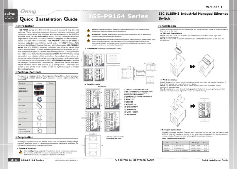
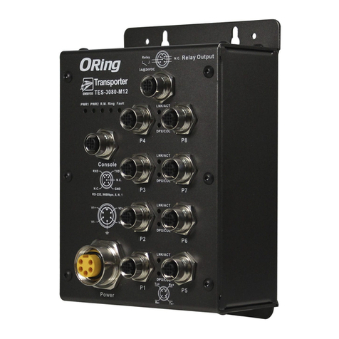
  9. ORiNG Transporter Series User manual

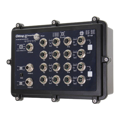
ORiNG Transporter Series User manual

68.00
79.30
180.00
Ø5.0
Ø11.05
Ø5.0
206.00
206.00
222.00
68.00
260.00
237.90
207.90
FaultRingR.M.PWR
Reset
3A@24 VDC
Relay N .C.
Rel ay Outp ut
Con sole
N.C.
RXD
RS-23 2, 9600 bps, 8, N , 1
GND
TXD
N.C.
P1
LNK/A CT
DPX/C OL
PoE
P2
LNK/A CT
DPX/C OL
PoE
P3
LNK/A CT
DPX/C OL
PoE
P4
LNK/A CT
DPX/C OL
PoE
P9
LNK/A CT
DPX/C OL
PoE
P10
LNK/A CT
DPX/C OL
PoE
P11
LNK/A CT
DPX/C OL
PoE
P12
LNK/A CT
DPX/C OL
PoE
P5
P6
P7
P8
P13
P14
P15
P16
LNK/
ACT
100M
LNK/
ACT
100M
Power
Failu re
Bypas s
Tx+ Rx +
Tx-Rx-
Tx+: Po E Vout+
Tx- : Po E Vout+
Rx+: Po E Vout-
Rx- : PoE Vo ut-
P1~ P16
Pow er
N.C.
N.C.
V+
V-
N.C.
G1/ G2
1.BI_ DA+
2.BI_ DA-
3.BI_ DB+
4.BI_ DB-
5.BI_ DD+
6.BI_ DD-
7.BI_ DC-
8.BI_ DC+
G2
G1
TPS-3 162GT- M12X- BP1-MV
Quick Installation Guide
Version 1.0
Quick Installation Guide
Introduction
PRINTED ON RECYCLED PAPER
Q I G
ORing's Transporter series managed Ethernet switches are designed for
TM
industrial applications, such as rolling stock, vehicle, and railway
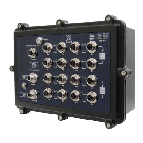
applications. The is a managed PoETPS-3162GT- M 1 2 X - BP1-MV
Redundant Ring Ethernet switch with 16x10/100Base-T(X) P.S.E. and
2x10/100/1000Base-T(X) ports which is specifically designed for the
toughest and fully compliant with EN50155 requirement. With completely
support of Ethernet Redundancy protocol, O-Ring (recovery time < 10ms
over 250 units of connection), O-Chain and MSTP/RSTP/STP (IEEE
802.1s/w/D) can protect your mission-critical applications from network
interruptions or temporary malfunctions with its fast recovery technology.
TPS-3162GT-M12X-BP1-MV also supports Power over Ethernet, a system
to transmit electrical power, along with data, to remote devices over
standard twisted-pair cable in an Ethernet network. Each TPS-3162GT-
M12X-BP1-MV switch has 16X10/100Base-T(X) P.S.E. (Power Sourcing
Equipment) ports. P.S.E. is a device (switch or hub for instance) that will
provide power in a PoE setup. EN50155TPS-3162GT-M12X-BP1-MV
Ethernet switch use M12 connectors to ensure tight, robust connections,
and guarantee reliable operation against environmental disturbances, such
as vibration and shock. can be managedTPS-3162GT-M12X-BP1-MV
centralized and convenient by a powerful windows utility ~ Open-Vision. In
addition, the wide operating temperature range from -40 C to 75 C can
o o
satisfy most of operating environment. Therefore, the switch is one of the
most reliable choices for rolling stock and highly-managed PoE Ethernet
application.
Package Contents
Installation
Wall-mount
The device can be fixed to the wall. Follow the steps below to install the device on the wall.
Step 1: Hold the evice upright against the walld
Step 2: Insert four screws through the large opening of the keyhole-shaped apertures at the
top and bottom of the unit and fasten the screw to the wall with a screwdriver.
Step 3: Slide the evice downwards and tighten the four screws for added stability.d
The device is shipped with the following items. If any of these items is
missing or damaged, please contact your customer service representative
for assistance.
Preparation
Before you begin installing the device, make sure you have all of the package
contents available and a PC with Microsoft Internet Explorer 6.0 or later, for
using web-based system management tools.
Elevated Operating Ambient: If installed in a closed environment, make sure
the operating ambient temperature is compatible with the maximum
ambient temperature (Tma) specified by the manufacturer.
Reduced Air Flow: Make sure the amount of air flow required for safe operation
of the equipment is not compromised during installation.
Mechanical Loading: Make sure the mounting of the equipment is not in a
hazardous condition due to uneven mechanical loading.
Safety & Warnings
For pin assignments of power, console and relay output ports, please refer to the following tables.
Contents
TPS-3162GT-M12X-BP1-MV
Pictures Number
1
CD 1
Dimension
Panel Layouts
Front View
1. Reset button
2. Power status LED
3. R.M. status LED
4. Ring status LED
5. Fault LED
6. Relay output port
7. Console port
8. Power connector
Wiring
Grounding
Grounding and wire routing help limit the effects of noise due to electromagnetic interference
(EMI). Run the ground connection from the grounding pin on the power connector to the grounding
surface prior to connecting devices.
Power port pinouts
The device supports one set of power supplies and uses the 7/8 inch 5-
pin male connector on the front panel for the power input.
Step 1: Insert a power cable to the power connector on the device.
Step 2: Rotate the outer ring of the cable connector until a snug fit is
achieved. Make sure the connection is tight.
N.C .
N.C .
V+
V-
Relay output port pinouts
Rela y N.C.
3A@2 4VDC
Network Connection
The switch has sixteen 10/100Base-T(X) and two 10/100/1000Base-T(X) Ethernet ports and 1 x
bypass included the form of M12 connector. Depending on the link type, the switch uses CAT 3, 4,
5,5e UTP cables to connect to network devices (PCs, servers, switches, routers, or hubs). Please
refer to the following table for cable specifications.
TPS-3162GT-M12X-BP1-MV
TPS-3162GT-M12X-BP1-MV 1907-200-J3162X1MV1-FX020
S w i tc h
E N 5 0 1 5 5
EN50155 18-port managed
PoE Ethernet switch
I N D U S T R I A L
1
Instead of screwing the screws in all the way, it is
advised to leave a space of about 2mm to allow
room for sliding the switch between the wall and the
screws.
The switch uses the M12 A-coded 5-pin female connector
on the front panel for relay output. Use a cable with an M12
A-coded 5-pin female connector to connect the relay. The
relay contacts will detect user-configured events and form
an open circuit when an event is triggered.
QIG 1
10
15
14
13
Console port pinouts
N.C.
RXD
RS-2 32 , 9600bps, 8, N , 1
GND
TXD
N.C.
9
11
4 52 3
Circuit Overloading: Consideration should be given to the connection of the equipment to
the supply circuit and the effect that overloading of the circuits might have on overcurrent
protection and supply wiring. Appropriate consideration of equipment nameplate ratings
should be used when addressing this concern.
Unit =mm (Tolerance ±0.5mm)
6
7
8
12
9. PoE Fast Ethernet ports
10. LNK/ACT indicator for PoE Fast Ethernet
port
11. PoE status LED for PoE Fast Ethernet ports
12. Duplex/collision indicator for
PoE Fast Ethernet port
13. Gigabit Ethernet ports with bypass
14. LNK/ACT indicator for Gigabit Ethernet port
15. Speed indicator for Gigabit Ethernet port
N.C .
4-Pin PoE Port Definition
Cable
Type
Max. Length
Connector
10BASE-T Cat. 3, 4, 5 100-ohm UTP 100 m (328 ft)
4-pin female M12 D-coding
connector
100BASE-TX Cat. 5 100-ohm UTP UTP 100 m (328 ft)
4-pin female M12 D-coding
connector
1000BASE-T Cat. 5/Cat. 5e 100-ohm UTP UTP 100 m (328 ft)
8-pin female M12 X-coding
connector
For pin assignments of the LAN ports, please refer to the following tables.
1
Tx+
2
Rx+
Tx-
3
Rx-
4
10/100Base-T(X) P.S.E. M12 port
Pin No. Description
#1 Tx+ with PoE Vout+
#2 Rx+ with PoE Vout-
#3 Tx- with PoE Vout+
#4 Rx- with PoE Vout-
Faul tRingR.M.PWR
Rese t
3A@2 4VDC
Rela y N.C.
Rel ay Outp ut
Con so le
N.C.
RXD
RS-2 32, 960 0bps, 8 , N, 1
GND
TXD
N.C.
P1
LNK/ ACT
DPX/ COL
PoE
P2
LNK/ ACT
DPX/ COL
PoE
P3
LNK/ ACT
DPX/ COL
PoE
P4
LNK/ ACT
DPX/ COL
PoE
P9
LNK/ACT
DPX/ COL
PoE
P10
LNK/ACT
DPX/ COL
PoE
P11
LNK/ACT
DPX/ COL
PoE
P12
LNK/ACT
DPX/ COL
PoE
P5
P6
P7
P8
P13
P14
P15
P16
LNK/
ACT
100M
LNK/
ACT
100M
Powe r
Fail ure
Bypa ss
Tx+ R x+
Tx-Rx-
Tx+: P oE Vout+
Tx- : P oE Vout+
Rx+: P oE Vout-
Rx- : Po E Vout-
P1~ P1 6
Pow er
N.C.
N.C.
V+
V-
N.C.
G1/ G2
1.BI _DA+
2.BI _DA-
3.BI _DB+
4.BI _DB-
5.BI _DD+
6.BI _DD-
7.BI _DC-
8.BI _DC+
G2
G1
TPS- 316 2GT-M 12X- BP1- MV
Q I G Quick Installation Guide
PRINTED ON RECYCLED PAPER
Quick Installation Guide
Version 1.0
Q I G
Specifications
S w i tc h
E N 5 0 1 5 5
I N D U S T R I A L
1. Launch the Internet Explorer and type in IP address of the device. The default static
IP address is 192.168.10.1
Follow the steps below to log in and access the system:
2. Log in with default user name and password (both are ).admin
3. After logging in, you should see the following screen. For more information on
configurations, please refer to the user manual. For information on operating the device
using ORing’s Open-Vision management utility, please go to ORing website.
Resetting
To restore the device configurations back to the factory defaults, press the button for 5Reset
seconds. Once the power indicator starts to flash, release the button. The device will then
reboot and return to factory defaults.
Configurations
After installing the and connecting cables, start the evice byswitch d
turning on power. The green power LED should turn on. Please refer to the
following tablet for LED indication.
EN50155 18-port managed
PoE Ethernet switch
LED
Color
Status
Description
PWR Green On DC power module activated
R.M Green On System running in Ring Master mode
Ring Green On System running in Ring mode
Fault Amber On Errors occur (power failure or port link down)
10/100Base-T(X) Ports
LNK/ACT Green On Port is linked
Blinking Transmitting data
PoE Green On Port providing power to PD
DPX/COL Amber On Port running in full-duplex mode
Blinking Collision occurs
10/100/1000Base-T Ports
LNK/ACT Green On Port is linked
Blinking Transmitting data
100M Green On Port speed at 100M
Power
Redund ant Input Pow er
Power Co nsumption(Typ.)
72 /110 (5 0.4- 137. 5) VDC . 7/8 inch 5-pi n male c onne ctor
28 w atts ( PoE p ower bu dget n ot inc lude d)
Physical Charac teristic
Enc losur e IP-3 0
Dim ensio n (W x D x H) 260 (W ) x 68 (D) x 222 (H) mm (10. 23 x 2.6 8 x 8.74 i nch. )
Weigh t (g) 28 50 g
Environmental
-40 to 85 C (-40 to 1 85 F)
o o
Sto rage Tempe ratu re
5% t o 95% Non -con dens ing
Ope rati ng Humi dity
Regulatory Appr ovals
CE EMC (EN 55 024, E N 5503 2), FC C Part 15 B, EN 5 0155
EMC
EN 55024 (I EC/E N 6100 0-4- 2 (ESD) , IEC/ EN 610 00-4-3 (RS) ,IEC /EN 61 000-4-4 (EF T),
IEC/EN 61 000- 4-5 (S urge), IEC/ EN 610 00-4 -6 (CS), IEC/ EN 610 00-4 -8(PFMF), I EC/E N 6100 0-4-11 (DIP ))
EMS
IEC60068-2-27
Sho ck
IEC60068-2-31
IEC6006 8-2- 6
Vib rati on
Fre e Fa ll
MTBF
26 1222 hr s
EN60950 -1
Saf ety
Fault Contact
Relay Relay outpu t to car ry cap acity of 3A at 2 4VDC on 5-pin A-co ding M 12 fem ale connect or
Overloa d Curre nt Protection
Revers e Polarity P rotec tion
Present
-40 to 75 C (-40 to 1 67 F)
o o
Ope rati ng Tem pera ture
ORi ng Switch M odel
10/ 100 Bas e-T(X) Port s in
M12 Auto MD I/MDIX with
P.S.E.
16 x M1 2 connect or (4-pin D-codin g, female )
Physical Ports
Technology
Eth ernet S tanda rds
IEEE 802.3 for 1 0Base-T
IEEE 802.3u fo r 100Base-TX
IEEE 802.3ab f or 1000Base-T
IEEE 802.3x fo r Flow control
IEEE 802.3ad f or LACP (Link Aggregati on Control Protocol)
IEEE 802.1D fo r STP (Spanning Tree Prot ocol)
IEEE 802.1p fo r COS (Class of Ser vice)
IEEE 802.1Q fo r VLAN Tagg ing
IEEE 802.1w fo r RSTP (Rapid Spanning Tr ee Protocol)
IEEE 802.1s fo r MSTP (Multiple Spann ing Tree Protocol)
IEEE 802.1x fo r Authenticati on
IEEE 802.1AB f or LLDP (Link Layer Disc overy Protocol)
IEEE 802.3af P oE specificat ion (up to 15.4 Watts per port for P.S.E.)
819 2 MAC add resse s
MAC Tabl e
4
Pri ority Queues
10/ 100/1 000Ba se-T(X ) ports
in M1 2 2 x M12 c onnectors (8-pin X-codin g, female )
RS- 232 Ser ial Con sole Port RS-23 2 in M12 connector (5 -pin A-co ding). Ba ud rate setting: 96 00bps, 8, N , 1
Sto re-a nd-Forward
Pro cessi ng
Sw itch Pr opert ies
Sw itchi ng late ncy: 7 us
Sw itchi ng band width : 7.2 Gbps
Max . Numbe r of Availa ble VLA Ns: 409 6
IGM P multi cast gr oups: 1 024
Port ra te limi ting: U ser Define
Sec urity Feat ures
Ena ble/d isabl e ports , MAC bas ed port s ecuri ty
Port bas ed netw ork acce ss cont rol (80 2.1x)
VLA N (802. 1Q) to se grega te and se cure ne twork t raff ic
Sup ports Q -in-Q V LAN for p erfor mance & s ecuri ty to exp and the V LAN spa ce
Radius ce ntra lized passwo rd mana gemen t
SNM P v1/v2 c/v3 en crypt ed auth entic ation a nd acce ss secu rity
Sof twar e Feat ures
STP /RSTP /MSTP ( IEEE 80 2.1D/ w/s)
Redund ant Ring (O-Rin g) with r ecov ery tim e less th an 10ms o ver 25 0 units
TOS/Di ffser v suppor ted
Qua lity of Service (802.1p) for r eal-t ime traffic
VLA N (802. 1Q) wit h VLAN ta gging a nd GVRP s uppor ted
IGM P Snoop ing for m ultic ast fil terin g
Port con figuration, statu s, stat istic s, moni torin g, secu rity
NTP f or sync hroni zing of c locks o ver ne twork
Sup port PT P Clien t (Prec ision T ime Pro tocol ) clock s ynchronizat ion
DHC P Server / Clie nt supp ort
Port Tru nk supp ort
MVR ( Multi cast VL AN Registration ) suppo rt
Mod bus TC P
Net work Redundancy
O-R ing
O-C hain
MRP * NOTE
STP
RST P
MST P
Warni ng / Moni torin g Syst em
Relay ou tput fo r fault e vent alarming
Sy slog se rver / client to record and view e vent s
Inc lude SM TP for event wa rning n otifi catio n via ema il
Event sel ectio n support
TPS -3162GT-M12X-BP1-MV
Total PoE budg et 90 w atts ( Max. 90 watt s)
*Note: This function is avai lable by request only.
ORing Industrial Networking Corp.
Copyright© 2019 ORing
All rights reserved.
TEL: +886-2-2218-1066
FAX: +886-2-2218-1014
Website: www.oringnet.com
E-mail: support@oringnet.com
Present
EN 55032, C ISPR 32, EN 6 1000 -3-2, E N 6100 0-3- 3, FCC Part 1 5 B class A
EMI
EN 50155
Oth er
Warranty
5 ye ars
8-Pin Gigabit Port Definition
10/100/1000Base-T(X) M12 port
Pin No. Description
#1 BI_DA+
#2 BI_DA-
#3 BI_DB+
#4 BI_DB-
#5 BI_DD+
#6 BI_DD-
#7 BI_DC-
#8 BI_DC+
TPS -3 162 GT-M 12X -BP 1-M V
TPS-3162GT-M12X-BP1-MV

This manual suits for next models

1

Other ORiNG Switch manuals

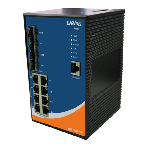
ORiNG IGS-9084GP-FB2-SS User manual

ORiNG

ORiNG IGS-9084GP-FB2-SS User manual

ORiNG IGPS-R9084GP User manual

ORiNG

ORiNG IGPS-R9084GP User manual

ORiNG IBS-102FX User manual

ORiNG

ORiNG IBS-102FX User manual

ORiNG IGS-9812GP User manual

ORiNG

ORiNG IGS-9812GP User manual

ORiNG IES-1050A User manual

ORiNG

ORiNG IES-1050A User manual

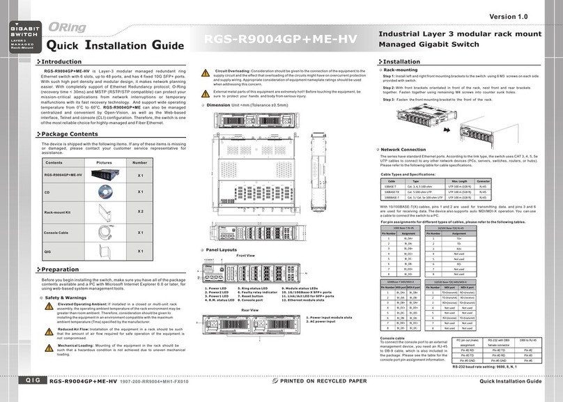
ORiNG RGS-R9004GP+ME-HV User manual

ORiNG

ORiNG RGS-R9004GP+ME-HV User manual

ORiNG IPS-1042FA-MM-SC User manual

ORiNG

ORiNG IPS-1042FA-MM-SC User manual

ORiNG IGS-P9164 Series User manual

ORiNG

ORiNG IGS-P9164 Series User manual

ORiNG IGS-9844GPFX Series User manual

ORiNG

ORiNG IGS-9844GPFX Series User manual

ORiNG TRGPS-9084TG-M12X-BP2-MV User manual

ORiNG

ORiNG TRGPS-9084TG-M12X-BP2-MV User manual

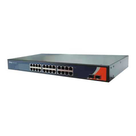
ORiNG RGS-9244GP User manual

ORiNG

ORiNG RGS-9244GP User manual

ORiNG IGPS-1042GPA User manual

ORiNG

ORiNG IGPS-1042GPA User manual

ORiNG TPS-3162GT-M12-BP1 User manual

ORiNG

ORiNG TPS-3162GT-M12-BP1 User manual

ORiNG IGS-9844 User manual

ORiNG

ORiNG IGS-9844 User manual

ORiNG RES-1242P User manual

ORiNG

ORiNG RES-1242P User manual

ORiNG IGS-1042GPA User manual

ORiNG

ORiNG IGS-1042GPA User manual

ORiNG IPS-2042TX Series User manual

ORiNG

ORiNG IPS-2042TX Series User manual

ORiNG IGPS-1080A User manual

ORiNG

ORiNG IGPS-1080A User manual

ORiNG IES-180-L User manual

ORiNG

ORiNG IES-180-L User manual

ORiNG DGS-9168GP-SS-AIO_S User manual

ORiNG

ORiNG DGS-9168GP-SS-AIO_S User manual

ORiNG IGPS-9042GP-24V User manual

ORiNG

ORiNG IGPS-9042GP-24V User manual

ORiNG RGS-R9244GP+ Series User manual

ORiNG

ORiNG RGS-R9244GP+ Series User manual

ORiNG TGPS-9084GT-M12X-BP2-MV User manual

ORiNG

ORiNG TGPS-9084GT-M12X-BP2-MV User manual

ORiNG TGPS-9164GT-M12X-BP2-24V User manual

ORiNG

ORiNG TGPS-9164GT-M12X-BP2-24V User manual

Popular Switch manuals by other brands

ADC LoopStar 745 Specification sheet

ADC

ADC LoopStar 745 Specification sheet

Nortel CVX 600 Hardware installation guide

Nortel

Nortel CVX 600 Hardware installation guide

Lenovo RackSwitch G8296 installation guide

Lenovo

Lenovo RackSwitch G8296 installation guide

Mellanox Technologies Spectrum SN2100 Hardware user manual

Mellanox Technologies

Mellanox Technologies Spectrum SN2100 Hardware user manual

MW MW-CTR-LUNA230 installation manual

MW

MW MW-CTR-LUNA230 installation manual

TP-Link TL-SG105E user guide

TP-Link

TP-Link TL-SG105E user guide

EtherWAN EX77900 Series installation guide

EtherWAN

EtherWAN EX77900 Series installation guide

ZyXEL Communications GS1100 Series user guide

ZyXEL Communications

ZyXEL Communications GS1100 Series user guide

D-Link DGS-1100-05PDV2 Quick installation guide

D-Link

D-Link DGS-1100-05PDV2 Quick installation guide

TRENDnet TE100 S800i Quick installation guide

TRENDnet

TRENDnet TE100 S800i Quick installation guide

Allied Telesis AT-8000S/24POE datasheet

Allied Telesis

Allied Telesis AT-8000S/24POE datasheet

Kontakt Simon TEW4 01 Series Technical data

Kontakt Simon

Kontakt Simon TEW4 01 Series Technical data

HP ProCurve 1600M Installation and getting started guide

HP

HP ProCurve 1600M Installation and getting started guide

Cisco 1548M quick start guide

Cisco

Cisco 1548M quick start guide

Televes MS54NG manual

Televes

Televes MS54NG manual

AYRSTONE AyrMesh quick start guide

AYRSTONE

AYRSTONE AyrMesh quick start guide

iPuray BRT-607 quick start guide

iPuray

iPuray BRT-607 quick start guide

Endress+Hauser Thermophant T TTR31 operating manual

Endress+Hauser

Endress+Hauser Thermophant T TTR31 operating manual

manuals.online logo
manuals.online logoBrands
  • About & Mission
  • Contact us
  • Privacy Policy
  • Terms and Conditions

Copyright 2025 Manuals.Online. All Rights Reserved.