manuals.online logo
Brands
  1. Home
  2. •
  3. Brands
  4. •
  5. ORiNG
  6. •
  7. Switch
  8. •
  9. ORiNG IGPS-1042GPA User manual

ORiNG IGPS-1042GPA User manual

IGPS-1042GPA
10/1 00/1 000T
3
4
1
2
5
PW1 PW2 Fa ult
6
1000M 100M
PoE
P5 P6
100/1000X
6
5
PWR- 1PWR- 2
V2- V2 + V1- V1 +
1A@2 4V DC 50 -57V
G
Quick Installation Guide
Introduction
PRINTED ON RECYCLED PAPER
Preparation
Before you begin installing the switch, make sure you have all of the package
contents available and a PC with Microsoft Internet Explorer 6.0 or later, for
using web-based system management tools.
Elevated Operating Ambient: If installed in a closed or multi-unit rack
assembly, the operating ambient temperature of the rack environment may be
greater than room ambient. Therefore, consideration should be given to
installing the equipment in an environment compatible with the maximum
ambient temperature (Tma) specified by the manufacturer.
Safety & Warnings
Dimension
Panel Layouts
1. PWR indicators
2. Faulty relay indicator
3. DIP switch
4. SFP port
5. Link/Act LED for SFP port
6. Link/Act LED for Gigabit
PoE LAN ports
7. PoE LED for LAN ports
8. Gigabit PoE LAN ports
Package Contents
Front View
The device is shipped with the following items. If any of these items is
missing or damaged, please contact your customer service representative for
assistance.
Installation
Step 1: Slant the switch and screw the Din-rail kit onto the back of the switch, right in
the middle of the back panel.
Step 2: Slide the switch onto a DIN-rail from the Din-rail kit and make sure the switch
clicks into the rail firmly.
DIN-rail Installation
Step 1: Screw the wall-mount kit onto the rear panel of the switch. A total of six
screws are required, as shown below.
Step 2: Use the switch, with wall mount plates attached, as a guide to mark the
correct locations of the four screws.
Step 3: Insert a screw head through the large parts of the keyhole-shaped apertures,
and then slide the switch downwards. Tighten the screws for added stability.
Wall-mounting
Q I G 1907-200-H1042GPAX2-FX011
Reduced Air Flow: Installation of the equipment in a rack should be such that the
amount of air flow required for safe operation of the equipment is not compromised.
Mechanical Loading: Mounting of the equipment in the rack should be such that a
hazardous condition is not achieved due to uneven mechanical loading.
Circuit Overloading: Consideration should be given to the connection of the equipment to
the supply circuit and the effect that overloading of the circuits might have on overcurrent
protection and supply wiring. Appropriate consideration of equipment nameplate ratings
should be used when addressing this concern.
Network Connection
The switch provides standard Ethernet ports. According to the link type, the switch uses
CAT 3,4,5,5e UTP cables to connect to any other network devices (PCs, servers,
switches, routers, or hubs). Please refer to the following table for cable
specifications.
Cable Types and Specifications:
Unit =mm (Tolerance ±0.5mm)
Features
Contents
Wall-mount Kit
DIN-rail Kit
IGPS-1042GPA
Pictures Number
X 2
X 1
QIG X 1
X 1
6-pin terminal block X 1 6
7
8
Rear View
1
1. Din-rail screw holes
Top Panel
1. Wall-mount screw holes
2. Terminal blocks: PWR1, PWR2
, Relay
3. DIP Switch
4. Ground wire.
2 3
4
1
1
is an unmanaged Ethernet Switch with 4x10/100/1000Base-T(X) P.S.EIGPS-1042GPA
ports with 2x100/1000Base-X SFP ports and extended operating temperature range from
-40°C to 75°C for the harsh environments. supports power over Ethernet,IGPS-1042GPA
a system to transmit electrical power, along with data, to remote devices over standard
twisted-pair cable in an Ethernet network. P.S.E is a device (switch or hub for instance)
that will provide power in a PoE setup. Therefore, the switch is one of the most reliable
choices for PoE Ethernet application.
Support 4 ports 10/100/1000Base-T(X) P.S.E ports.
Support IEEE 802.3at compliant PoE and total power budget is 120Watts with
maximum 30Watts per port.
Support auto-negotiation and auto-MDI/MDI-X
Support store and forward transmission
Support flow control
Support Jumbo frame up to 10K Bytes
Provide Relay output for power failed warning system
Rigid IP-30 housing design
DIN-Rail and wall mounting enabled
IGPS-1042GPA
94.9
68.15
8.0
14.0 6.0 5
25.0
50.0
25.5
8.5
25.6
24.3
Ø5.9
Ø3.0
26.1
144.3
12.3
13.1
24.3
Ø4.0
12
Version 2.1
Quick Installation Guide
Industrial Unmanaged Gigabit PoE Switch
Cable Type Max. Length Connector
10BASE-T Cat. 3, 4, 5 100-ohm UTP 100 m (328 ft) RJ-45
100BASE-TX Cat. 5 100-ohm UTP UTP 100 m (328 ft) RJ-45
1000BASE-T Cat. 5 / Cat. 5e 100-ohm UTP UTP 100 m (328 ft) RJ-45
G I G A B I T
I N D U S T R I A L
S W I T C H
P o E
IGPS-1042GPA
IGPS-1042GPA
10/100/1000T
3
4
1
2
5
PW1 P W2 Faul t
6
1000M 100M
PoE
P5 P6
100/1000X
6
5
3
4
5
IGPS-1042GPA
10/10 0/10 00T
3
4
1
2
5
PW1 P W2 Faul t
6
1000M 100M
PoE
P5 P6
100/1000X
6
5
Q I G Quick Installation Guide
Quick Installation Guide
Q I G
G I G A B I T
I N D U S T R I A L
S W I T C H
P o E
DIP Switch Setting (Power Side)
Wiring
The switch supports dual redundant power supplies, Power Supply1
(PWR1) and Power Supply 2 (PWR2). The connections for PWR1,
PWR2 and the RELAY are located on the terminal block.
STEP 1: Insert the negative/positive wires into the V-/V+ terminals,
respectively.
STEP 2: To keep the DC wires from pulling loose, use a small flat-
blade screwdriver to tighten the wire-clamp screws on the front of the
terminal block connector.
PWR-1PWR-2 1A@ 24V
V2- V2+ V1- V1+
Power inputs
The two sets of relay contacts of the 6-pin terminal block connector are used to detect user-
configured events. The two wires attached to the fault contacts form an close circuit when a
user-configured event is triggered. If a user-configured event does not occur, the fault
circuit remains opened.
Relay contact
Grounding and wire routing help limit the effects of noise due to electromagnetic
interference (EMI). Run the ground connection from the ground screws to the grounding
surface prior to connecting devices.
Grounding
Configurations
After installing the switch, the green power LED should turn on. Please refer
to the following tablet for LED indication.
For pin assignments for different types of cables, please refer to the following
tables.
Note: “+” and “-” signs represent the polarity of the wires that make up each
wire pair.
ORing Industrial Networking Corp.
Copyright© 2013 ORing
All rights reserved.
TEL: +886-2-2218-1066
FAX: +886-2-2218-1014
Website: www.oringnet.com
E-mail: support@oringnet.com
Version 2.1
10/100Base-T(X) P.S.E. RJ-45 port
Pin No.
Description
#1
TD+ with PoE Power Input +
#2
TD- with PoE Power Input +
#3
RD+ with PoE Power Input -
#4
N.C.
#5
N.C.
#6
RD- with PoE Power Input -
#7
N.C.
#8
N.C.
1000Base-T P.S.E. RJ-45 port
Pin No.
Description
#1
BI_DA+ with PoE Power Input +
#2
BI_DA- with PoE Power Input +
#3
BI_DB+ with PoE Power Input -
#4
BI_DC+
#5
BI_DC-
#6
BI_DB- with PoE Power Input -
#7
BI_DD+
#8
BI_DD-
LED
Color
Status
Description
PW1 Green On DC power 1 activated
PW2 Green On DC power 2 activated
Fault Amber On Faulty relay (power failure or port disconnected)
10/100/1000Base-T(X) Gigabit PoE Ethernet ports
LNK/ACT
Green On Port link at 1000Mbps
Amber On Port link at 10/100Mbps
PoE Green On Power supplied over Ethernet
SFP Port
LNK/ACT Green On Port is linked
Industrial Unmanaged Gigabit PoE Switch
DIP-2
OFF
DIP-1
1000Mbps
Description
ON 100Mbps
port 5port 6
DIP Switch Setting (SFP Speed Selection)
Specifications
ORing Switch Model
Physical Ports
Technology
Ethernet Sta n dards
LED Indicators
Green: Power LED x2Pow e r in dicator
10/100/ 1000Bas e-T(X) P.S.E.
Por t in RJ45 Auto M DI/MDIX
IGPS-1042GPA
4
IEEE 802.3 for 10Ba se-T
IEEE 802.3u for 100 Base-TX
IEEE 802.3ab for 10 00Base-T
IEEE 802.3z for 100 0Base-X
IEEE 802.3x for Flo w control
IEEE 802.3at PoE speci ficati on
MAC Table 1024
Environmental
-40 to 85 C (-40 to 18 5 F )
o o
Storage Tem p era t ure
Operating Temperature
5% to 95% Non-co n densingOperating Humid i ty
Regulatory Approvals
CE EMC (EN 55024 , E N 55032), FCC Part 15 B
EMC
EN 55024 (IEC/ E N 61000-4-2 (E S D: Contact 4KV, Air 8 K V), IEC/EN 6100 0 -4-3 (RS: 3V),
IEC/EN 61000 - 4-4 (EFT Power 0.5 K V, Signal 0 . 5KV),
IEC/EN 61000 - 4-5 (Surge: Power 0. 5 KV, Signa l 1 KV), IEC/EN 610 0 0-4-6 (CS: 3V) ,
IEC/EN 61000 - 4-8(PFMF), I E C/EN 61000-4 - 11 ( DIP))
EMS
IEC60068-2 - 27Shock
IEC60068-2-31
IEC60068-2 - 6Vibration
Free Fall
MTBF
910925 hours
-40 to 75 C (-40 to 16 7 F )
o o
Amber: Indic a te PWR1 or PWR2 fai l ure
Fault indi c ator
Fault Contact
Rel ay Relay ou t put to carry capa c ity of 1A at 24 VDC
Power
Red u ndant Input pow e r
PoE Power B u dget
<6.5Wat t s, 0.13-0.11A
Overload curr e nt protection
Rever s e polarity prot e ction
Present
Present
Physical Characteristic
Enclosure IP - 30 Metal
Dimension (W x D x H)
Weight (g ) 458g
Dual 50~57VD C o n 6-pin termina l b lock
26.1 (W) x 94.9 (D ) x 1 44 .3 (H) mm (1.03 x 3.7 4 x 5 .68 inches)
10/100/100 0 Base-T(X) RJ45
port indicat o r and Po E i ndicator
Upper LED for Li n k/Act indicat o r: Green for por t L in k/Act
Lower LED for PoE indi c ator, Green for PoE power e n able
EN 60950-1 (LVD)Safety
DIP Switch for power fail alarm
Pow e r 1 fa il warning: ON for E n able, OFF for dis a bleDIP-Switch 1
Pow e r 2 fa il warning: ON for E n able, OFF for dis a ble
DIP-Switch 2
Processing S t ore-and-Forward
100/1000Ba s e-X SFP por t 2
Green for port L i nk/Act.
100/1000Ba s e-X SFP por t i ndicator
DIP Switch for SFP port speed
ON: 100Mbps, O F F: 1000 M bps(defaul t )
DIP switch 1(S F P Port 6 )
Jumbo Frame Up to 10KBytes
Pow e r consumption ( Typ.)
120W max, 30W pe r p ort
EN 55032, CISP R 32, EN 61000-3- 2 , EN 61000-3-3 , F CC Par t 1 5 B cl ass AEMI
Warranty
5 ye ars
Pac ke t b uffer 1M bit s
Sw itch Propert i es
Sw itching laten c y: 7 us
Sw itching bandw id th: 12Gbps
Throughput ( p acket per second ) : 8 .688Mpps@6 4 By tes packet
ON: 100Mbps, O F F: 1000 M bps(defaul t )
DIP switch 2(S F P port 5)
Hardware Ve r sion V5.0
PRINTED ON RECYCLED PAPER
IGPS-1042GPA
DIP-2
OFF
OFF
ON
DIP-1
Power failure relay alarm disabled
PWR-1 failure, relay alarm enabled
PWR-2 failure, relay alarm enabled
OFF
ON
OFF
Description
ON PWR-1 or PWR-2 failure,
relay alarm enabled
ON
IGPS-1042GPA

Other ORiNG Switch manuals

ORiNG IGPS-R9084GP User manual

ORiNG

ORiNG IGPS-R9084GP User manual

ORiNG IES-3080 Series User manual

ORiNG

ORiNG IES-3080 Series User manual

ORiNG IES-3240 User manual

ORiNG

ORiNG IES-3240 User manual

ORiNG IGS-1042GPA User manual

ORiNG

ORiNG IGS-1042GPA User manual
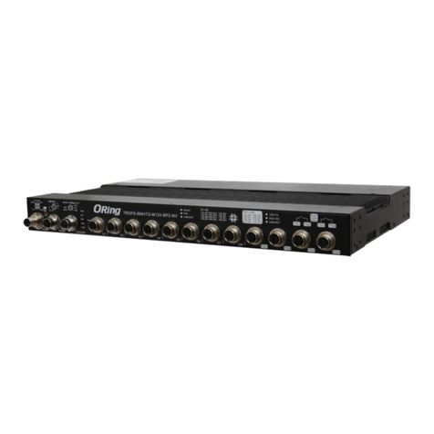
ORiNG TRGPS-9084TG-M12X-BP2-MV User manual

ORiNG

ORiNG TRGPS-9084TG-M12X-BP2-MV User manual

ORiNG RGS-R9244GP+ Series User manual

ORiNG

ORiNG RGS-R9244GP+ Series User manual

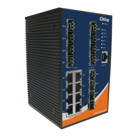
ORiNG IGS-9084GP User manual

ORiNG

ORiNG IGS-9084GP User manual

ORiNG TPS-3162GT-M12-BP1 User manual

ORiNG

ORiNG TPS-3162GT-M12-BP1 User manual

ORiNG IGS-1042GPA User manual

ORiNG

ORiNG IGS-1042GPA User manual
ORiNG IGPS-9084GP User manual

ORiNG

ORiNG IGPS-9084GP User manual

ORiNG TGXPS-1080-M12-24V Series User manual

ORiNG

ORiNG TGXPS-1080-M12-24V Series User manual

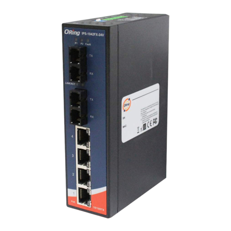
ORiNG IPS-2042 Series User manual

ORiNG

ORiNG IPS-2042 Series User manual

ORiNG IGPS-1080A User manual

ORiNG

ORiNG IGPS-1080A User manual

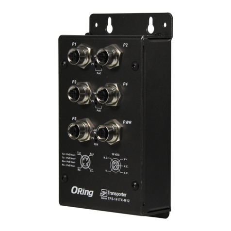
ORiNG TPS-141TX-M12 Series User manual

ORiNG

ORiNG TPS-141TX-M12 Series User manual

ORiNG TES-3080-M12 Series User manual

ORiNG

ORiNG TES-3080-M12 Series User manual

ORiNG IGS-9084GP-FB2 User manual

ORiNG

ORiNG IGS-9084GP-FB2 User manual

ORiNG IES-1080A User manual

ORiNG

ORiNG IES-1080A User manual

ORiNG TPS-3882GT-M12-BP1 User manual

ORiNG

ORiNG TPS-3882GT-M12-BP1 User manual

ORiNG IGS-9848GPF User manual

ORiNG

ORiNG IGS-9848GPF User manual

ORiNG IGPS-1411GTPA User manual
ORiNG

ORiNG IGPS-1411GTPA User manual

ORiNG IPS-1080-24V User manual

ORiNG

ORiNG IPS-1080-24V User manual

ORiNG TXPS-1080-M12-24V Series User manual

ORiNG

ORiNG TXPS-1080-M12-24V Series User manual

ORiNG IGPS-9080-24V User manual

ORiNG

ORiNG IGPS-9080-24V User manual

ORiNG IGPS-1082GP Series User manual

ORiNG

ORiNG IGPS-1082GP Series User manual

Popular Switch manuals by other brands

ABK PA-2088S owner's manual

ABK

ABK PA-2088S owner's manual

Leviton W5603 manual

Leviton

Leviton W5603 manual

Offgridtec US-12N operating instructions

Offgridtec

Offgridtec US-12N operating instructions

Siemens SIMATIC NET RUGGEDCOM RSG2488F installation manual

Siemens

Siemens SIMATIC NET RUGGEDCOM RSG2488F installation manual

Arista DCS-7508 quick start guide

Arista

Arista DCS-7508 quick start guide

Bay Networks 281xSA Using

Bay Networks

Bay Networks 281xSA Using

Alloy POEGEM12T2SFP user manual

Alloy

Alloy POEGEM12T2SFP user manual

Covid MH22-220 user manual

Covid

Covid MH22-220 user manual

MiLAN MIL-S8000G user guide

MiLAN

MiLAN MIL-S8000G user guide

Crestron GreenLight DIN-8SW8 Operations & installation guide

Crestron

Crestron GreenLight DIN-8SW8 Operations & installation guide

ENSIM SENSORS DX-ECAS Series manual

ENSIM SENSORS

ENSIM SENSORS DX-ECAS Series manual

Altimium SCA51TS user manual

Altimium

Altimium SCA51TS user manual

AbleNet Big Beamer quick start guide

AbleNet

AbleNet Big Beamer quick start guide

Extron electronics SW2 HDMI Specifications

Extron electronics

Extron electronics SW2 HDMI Specifications

Teknion KDH064B User instruction

Teknion

Teknion KDH064B User instruction

ATEN VM7814 quick start guide

ATEN

ATEN VM7814 quick start guide

Fujitsu series3-1621 User giude

Fujitsu

Fujitsu series3-1621 User giude

Accton Technology USB204A Quick installation guide

Accton Technology

Accton Technology USB204A Quick installation guide

manuals.online logo
manuals.online logoBrands
  • About & Mission
  • Contact us
  • Privacy Policy
  • Terms and Conditions

Copyright 2025 Manuals.Online. All Rights Reserved.