Q I G Quick Installation Guide
PRINTED ON RECYCLED PAPER
Quick Installation Guide
Version 2.1
Q I G
LED indication table
Specifications
Q I G
Wiring
PW1 Green On DC power module 1 activated
PW2 Green On DC power module 2 activated
Fault Amber On Faulty relay (power failure or port disconnected)
ORing Industrial Networking Corp.
Copyright© 2011 ORing
All rights reserved.
TEL: +886-2-2218-1066
FAX: +886-2-2218-1014
Website: www.oringnet.com
E-mail: support@oringnet.com
PWR-1PWR-2
V2- V2+ V1- V1+
1A@24V
The switch supports dual redundant power supplies, Power Supply1
(PWR1) and Power Supply 2 (PWR2). The connections for PWR1,
PWR2 and the RELAY are located on the terminal block.
STEP 1: Insert the negative/positive wires into the V-/V+ terminals,
respectively.
STEP 2: To keep the DC wires from pulling loose, use a small flat-blade
screwdriver to tighten the wire-clamp screws on the front of the
Power inputs
The two sets of relay contacts of the 6-pin terminal block connector are used to detect user-
configured events. The two wires attached to the fault contacts form an open circuit when a
user-configured when an event is triggered. If a user-configured event does not occur, the
fault circuit remains closed.
Relay contact
Configurations
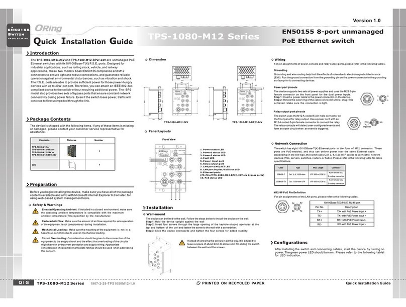
After installing the IBS-102FX and connecting cables, start the switch by turning on power.
The green power LEDs should turn on.and
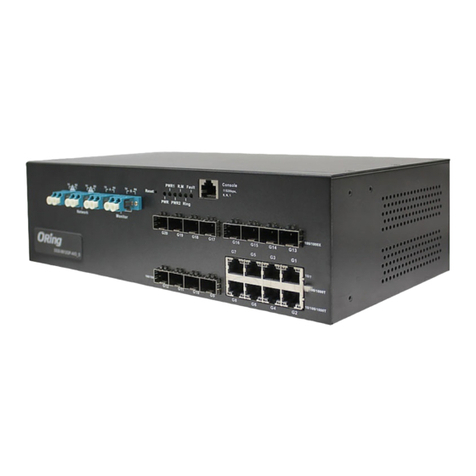
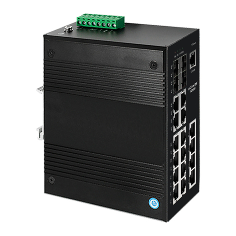
IBS-102FX Series
B Y PA SS
I N D U S T R I A L
S W I T C H
Industrial Optical Bypass Switch
Practical Operation
The Bypass switch deliver the
data between the Network ports
and the Monitor (local) ports
Normal mode:
The N etw ork d ata traffi c
routed directly to the other
Network port. And the Monitor
data traffic routed directly to
the other Monitor port.
Bypass mode:
Nomal mode Bypass mode
P1 P 2 Fault
IBS -102FX
A
A
100M / 1G / 10 G bp s
Network
B
TX
RX
B
TX
RX
TX
RX
TX
RX
Moni tor
Alar m
P1
P2
DIP Switch Function
DIP-2
OFF
OFF
ON
DIP-1
Power failure relay alarm disabled
PWR-1 failure, relay alarm enabled
PWR-2 failure, relay alarm enabled
OFF
ON
OFF
Description
ON PWR-1 or PWR-2 failure,
relay alarm enabled
ON
ORing Bypass Switch Model
Physical Ports
Fiber Ethernet
Optical Fiber
DIP Switch Setting
Power-1 failed warning detection: (On) relay enabled (Off ) relay disabledDIP-Swicth No.1
LC connector
IBS-102FX-SS-LC
4 Duplex Single-mode LC
connector
Single-mode: 9/125 mµ
Operating Wavelength 1310 40, 1550 40 nm± ±
Environmental
-40 to 85 C (-40 to 185 F)
o o
Storage Temperature
Operating Temperature
5% to 95% Non-condensingOperating Humidity
Regulatory approvals
CE EMC (EN 55024, EN55032), FCC Part 15BEMC
EN 55024 (IEC/EN 61000-4-2,(ESD), IEC/EN 610000-4-3(RS),
IEC/EN 61000-4-4 (FET),IEC/EN61000-4-5 (Surge),
IEC/EN61000-4-6 (CS), IEC/EN61000-4-8(PFMIF), EN61000-4-11(DIP))
EMS
IEC60068-2-27Shock
IEC60068-2-31
IEC60068-2-6Vibration
Free Fall
MTBF
1246758hrs
-40 to 75 C (-40 to 167 F)
o o
DIP-Switch No.2
Fault contact
Relay Relay output to carry capacity of 1A at 24 VDC
Power
Input power
Power consumption (Typ.) 2.7 Watts
Overload current protection Present
Physical Characteristic
Enclosure IP-30
Dimension (W x D x H)
Weight (g) 405g
Dual 12~48 VDC power inputs at DC-Jack and 4-pin terminal block
26.1(W)x94.9(D)x144.3(H) mm (1.03x3.74x5.68inch.)
LED Indicators
Green : power LED x 2.Power indicator
Green On : Operated in normal mode
Normal indicator
IBS-102FX-MM-LC
4 Duplex Multi-mode LC
connector
Multi-mode: 50/125µm or 62.5/125µm
Insert loss typical1.2 dB , Maximun 2 dB
Switching time < 8ms
Power-2 failed warning detection: (On) relay enabled (Off ) relay disabled
Amber for power failed indicator
Fault Indicator
850 40, 1310 40 nm± ±
typical1.2 dB , Maximun 1.6 dB
Reverse Polarity Present on Terminal Block
EN 55032, CISPR32, EN 61000-3-2, EN 61000-3-3, FCC Part 15B class AEMI
Warranty
3 years
IBS-102FX Series
