R2 TST Series Instructions for use

ENGLISH
Stoneburier
Mod. TST - TSThi
Instructions and maintenance manual
(Translation of the original instructions)

Index Pag.
Introduction............................................................................................................................... 3
Machine identification………………………………………………………………………………... 3
Description of the machine and its proper use.…………………………………………………… 4
Technical specifications and dimensions................................................................................. 5
Handling and transportation of the machine………………………………………………………. 5
Accident prevention.................................................................................................................. 6
Components assembly and coupling of the working equipment………………………………... 7
Cardan shaft connection…………………………………………………………………………….. 8
Preparation for use…………………......................................................................................... 9
Working depth adjustment………............................................................................................. 9
Levelling adjustment…............................................................................................................. 9
Machine use…………………………………………………………………………………………... 10
Maintenance............................................................................................................................. 11
Hoes replacement.................................................................................................................... 12
End of work and storage of the machine.................................................................................. 13
Scrapping and disposal of the components and packaging …………………………………… 13
Specific references for the hydraulic machines…………………………………………………… 14
Guarantee and Certification….................................................................................................. 18
WARNING
Always keep a safe distance when you are in view of the danger symbol placed on the side and back
of the machine.
ATTENTION cardan shaft in movement, danger of entanglemnet while turning. DO NOT TOUCH. DO
NOT APPROACH.
PTO tractor speed: 540 RPM
Before using the machine read the instruction booklet.
Turn off the tractor before making any adjustment in the machine , take the
key and read the instruction booklet.
ENGLISH 2
2

3 3
ENGLISH
Introduction
We would like to start by thanking you for having chosen our product and hope that you will be
happy with your choise.
In order that your STONEBURIER Mod. TST-TSThi can offer the maximum efficiency for many
years, we ask you to pay attention to the use and maintenance instructions which you will find in this
manual. Observance of these regulations will prevent breakdowns and accidents for which our
company will not accept responsability.
This use and maintenance manual is to be considered an integral part of the machine and therefore
it must always accompany the machine when it is sold, even in the event of its sale to third parties.
If you keep this manual in a safe place and in good condition, you - and whoever must use the
machine - will be able to have a complete, legible reference on hand at all times.
Description of the symbols used in the manual
This symbol will be used in the
manual to indicate actions
( misuse ) elements, behaviours
and situations that could risk
your security and the one of
other people.
The rounded symbols with
white pictograms will be used in
the manual to indicate the
Individual Protective Devices
necessary while using the
machine or while making any
adjustments.
This symbol will be used in this
manual to indicate that the
described operation must be
done with the walking tractor or
tractor turned off and the key
disconnected
NOTE: : This manual concerns the use and maintenance description of the mechanic Stoneburiers
TST which corrisponds largely to the hydraulic models TSThi; the differences between the two
models will be indicated with a caption.
(*note n mod. hi) (nindicates the note number)
and examined in an specific section of the manual.
1 - Machine identification
Each R2 machine has a CE plate with the main details of the R2 company and of the machines.
The plate is positioned on the lateral upper part of the machine.
Fig. 1

2 - Description of the machine and its proper use
(*note 1 mod. hi)
The STONEBURIER Mod. TST-TSThi is the only machine that applied to low powered tractors,
mills, buries the stones, levels and compresses the soil in a single operation.
As it can be seen from the illustration (Fig. 2) the STONEBURIER Mod. TST-TSThi has a milling
group to work the soil and to bury the stones, an adjustable- height scraper to level the soil, and a
particular mesh roller to tamp the soil and to adjust the working depth.
The STONEBURIER Mod. TST-TSThi is especially indicated for the soil preparation where it is
necessary to bury stones and weed. For a better result, we advise you to use the machine in a soil
previously broken up.
Fig. 2
A – Main body of
the machine
(stoneburier )
B –Roller group.
C –Register roller
adjustment
D – Scraper
E- Three-point
linkage
THE STONEBURIERS Mod. TST-TSThi are designed to be applied exclusively to
professional driven tools (tractors with three-point linkage and PTO 540 r.p.m. or hydraulic
drive) with EC certificated an with appropriate HP.
The STONEBURIERS Mod. TST-TSThi are deigned exclusively for the soil working.
Any other type of use is considered improper and dangerous. In all those cases that the
STONEBURIER Mod. TST-TSThi are used for different purposes of those determined , the
manufacturer disclaims any liability for damages of any nature.
Read always the instruction booklet of the working equipment (tractor) before fitting and using the
R2 machine.
The proper use of the machine implies:
-The respect of the rules of use and maintenance established by the manufacturer and gathered in
this manual.
-the exclusive use of spare parts and original R2 accessories
The machine must be used, maintained and repaired only by competent staff.
The qualified staff enabled to use the machine must be properly trained and informed of the proper
use of the equipment and the risks that could be run.
The user is required to comply with the rules and existing Legislation relating to fire prevention,
safety at work and traffic in public roads
C
D
E
B
A
ENGLISH 4
4

3 - Technical specifications and dimensions
(*note 2 mod. hi) Model
TST100 TST113 TST130 TST 150
Milling width (Fig. 3 – Ref. A) 100 cm 113 cm 130 cm 150 CM
Levelling width (Fig. 3 – Ref. B) 100 cm 113 cm 130 cm 150 CM
Compactness width (Fig. 3 – Ref. C) 121 cm 132 cm 150 cm 170 CM
Depth (Fig. 3 – Rif D) 110cm 110cm 110cm 110cm
Maximum height from the ground (Fig. 3 – Ref. E) 80 cm 80 cm 80 cm 80 cm
Tractor HP 16-30 HP 18-30 HP 23-30 HP 30 – 40 HP
Maximum working depth 14 cm 14 cm 14 cm 14 cm
Number of Hoes 28 32 36 40
Weight 195 Kg 218 Kg 240 Kg 280 Kg
Chain Lubricant: ROLOIL LITEX - EP/ 2
Gear Box lubricant : ROLOIL Dolomiti super HD Turbo/15W40
Note: Emission of airborne noise. The noise produced by the machine varies according to the soil
features at work. Exposure also depends strictly on the noise produced by the tractor. Considering the
data in the literature relating to similar equipment, it can be considered an approximate value of exposure
to the noise determined by the tractor between 90 dB (A) and 95 dB (A).
Verify the level of exposure to the noise with the proper instruments each time any work is performed. Follow the legislative
references of your country to identify the personal protective necessary equipment
Fig. 3
5 5
ENGLISH
Fig. 4a
Fig. 4b
4 - Handling and machine transportation
(*note 3 mod. hi)
- The machine must be handled with lifting equipment Make sure that such equipment (including the
straps and the strings ) have a carrying capacity appropriate to the weight to be lifted and that they
are in good maintenance conditions.
E
A-B
D
C
55°
. The machine can be anchored:
a) while unpacking it (three point linkage frame not assembled): through the arms lifting tractor
connection(Fig. 4a).
b) machine completely assembled through the three point pin (Fig. 4b)
Due to the centre of gravity, the machine will lean about 55° while lifting it.
In order to make handling operations safely , always wear safety shoes and
make sure that there are no people or animals nearby while working.
- The machine must be transported by professional means of conveyance (trucks, vans, etc.).Do not
use carry the machine in a car. In all cases, before transporting the machine , make sure that it is well
anchored with straps and strings and that it is stable enough. The anchor points can be the roller
group support, the three point linkage pin, the coupling tractor arms and the roller support.
- Always check that any walkways, ramps, etc. that must be crossed are well anchored and have a
capacity capable of supporting the total load of the vehicle + machine + operator. When using ramps
for loading, ensure that the vehicle has the handbrake on and have been positioned the wedges
suitable for locking the wheels.

5 - Accident prevention
(*note 4 mod. hi)
Most accidents that happen at work, during the maintenance or the shifting of a
machine, are due to negligence in the observance of the most elementary rules of
accident prevention
It is, therefore, necessary that whoever uses the machine read and respect the rules written below
and the ones on the adhesive stickers of the machine.
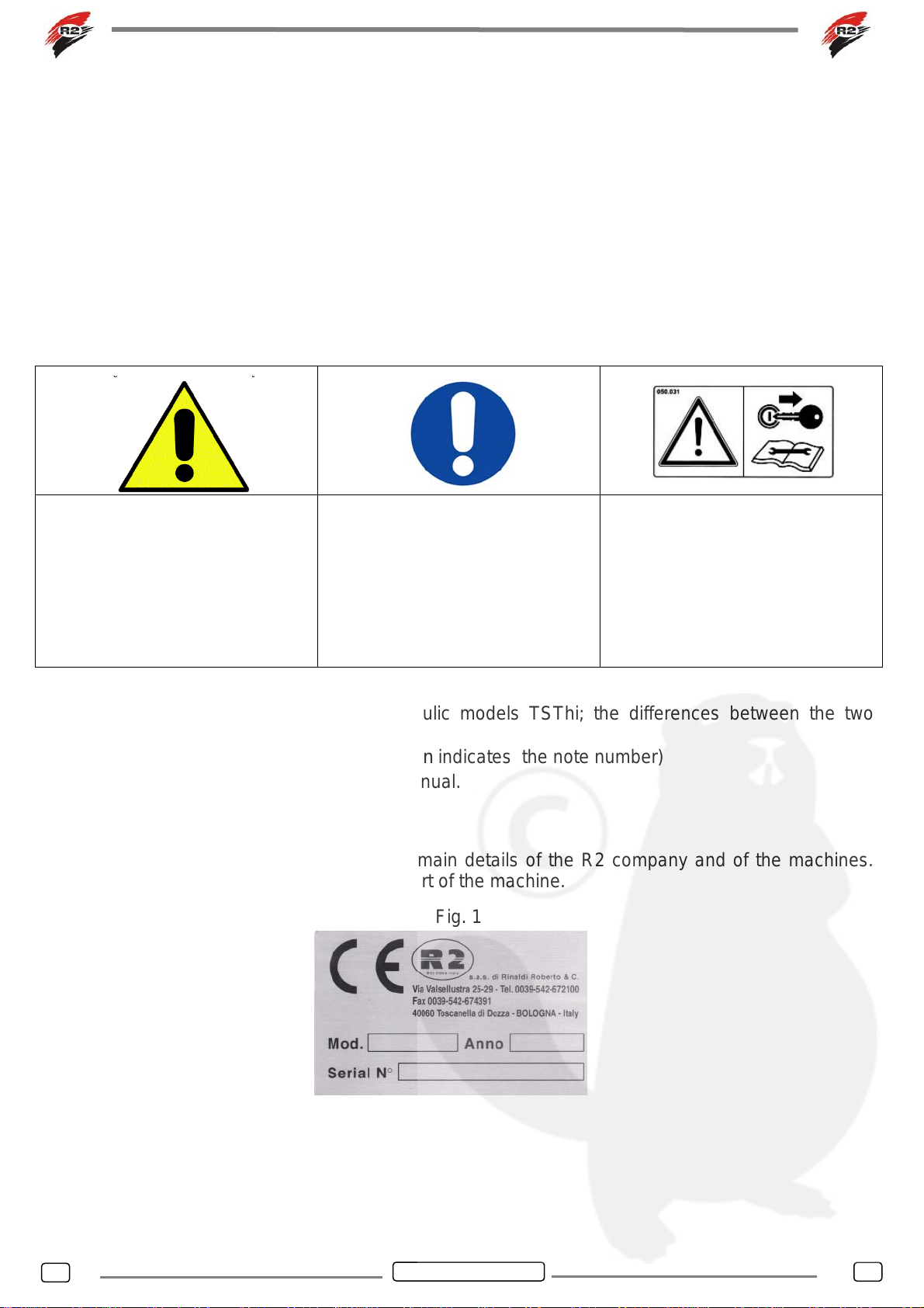
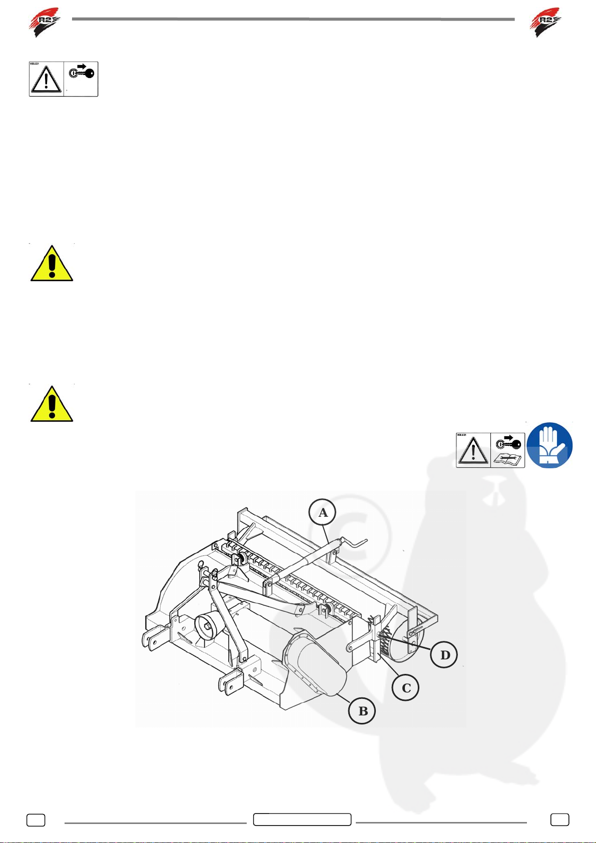
1. Verify that on the machine are stuck all the security signs and that they are readable.
2. Before cleaning the machine, making any adjustments or reparations, turn off the tractor
engine. Before each operation put the machine on the floor or on steady supports.
3. Never approach to the machine moving parts
4. The STONEBURIER Mod. TST – TSThi has been manufactured for a specialized use. It
must, therefore,always be in perfect working conditions and only R2 spare parts should be
used when making any reparations.
5. Before using the machine , check the tightening of the nuts and screws, in particular those of
the hoes and the three point-linkage
6. Keep away all the people or animals before starting to work.
7. Be careful when working alongside roads, pathways or sloping ground.
8. Do not leave the machine working without supervision.
9. While checking or repairing the machine, be sure that nobody can start it up accidentally.
10.Wear tight-fitting clothes that do not cause any footholds in the rotating parts of the machine .
11.Do not climb on the machine at work.
12.Do not interfere with objects on the machine while working.
13.Never use the machine without the back roller or without the protections delivered with the
machine. Never remove the protections.
14.In order to adjust the scraper, always turn off the tractor engine and make this operation
safely.
15.In case the machine blocks, before making any reparations, turn off the tractor engine and
remove the key
16.Always read the tractor instruction booklet before fitting and using the R2 machine. Do not
remove or evade the security systems of the tractor; before start working, be sure that the
security systems of the tractor work correctly; if not, do not use the machine.
17. Do not carry people , animals or objects on the machine.
18.In case of road traffic respect the regulations in force in your country; put on the machine all
the signals required; always verify the maximum weight allowed on the wheel axle. Pay
attention: the road holding, the stability in cornering and the tractor braking can result different
because of the presence and position of the machine.
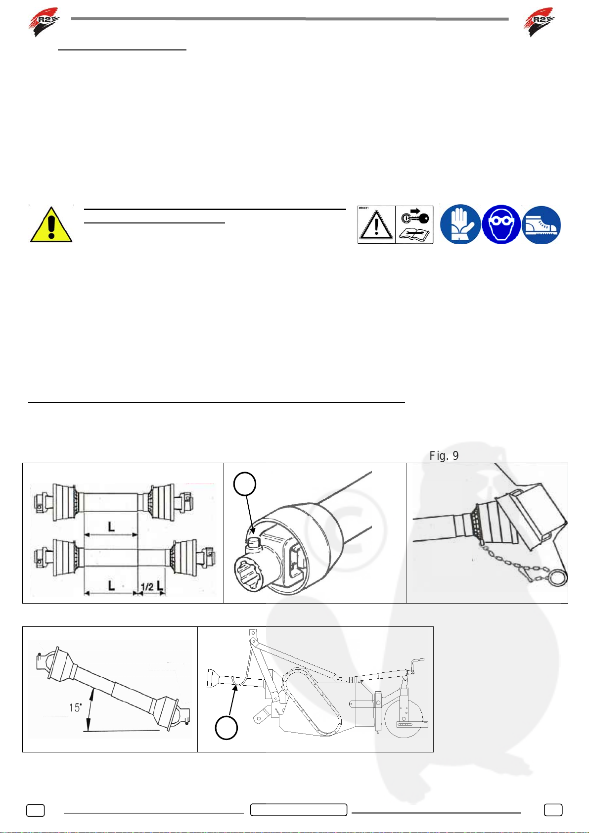
19.While fixing the cardan always follow the instructions given by the constructor.(the cardan’s
operation and maintenance manual) and the instructions illustrated in this booklet.
20.Be very careful while assembling the machine to the tractor.
21.The diameter of the machine pins for the tractor connection, must correspond to the balls of
connection of the tractor.
22.Do not go near and do not allow anyone to approach in the area of the tractor lifting
ENGLISH 6
6

6 – Components assembly and tractor coupling.
(*note 5 mod. hi)
The assembly must be made on a steady surface or on an homogeneous level floor.
During the assembly wear leather gloves and accident-prevention shoes.
If pneumatic wrenches are used, wear the ear
protections
6.1 Assembly of the three-point linkage frame.
- Assembly the roller support to the machine through the arms (Fig. 5 Rif. A) tightening the bolts and
nuts so that the support can turn during the adjustement;
- Assemble the register roller adjustment as indicated in figure (Fig. 5 - Rif. B) tightening the bolts and
nuts so that the register roller and the support can turn during the adjustment;
Assemble the zinced sides (Fig. 5 – Rif. C) as indicated in the figure;
- Assemble the grid (Fig. 5 Rif. D), tightening the bolts in such a way that the rubber cylinders leave a
partial elasticity of the grid with respect to the machine.
-Assemble the three point linkage frame (Fig.5 – Ref. E) to the supports(Fig. 5 – Ref. F) as shown in
the figure(note:the elements that make part of the frame must be screwed outside the supports).
Thighten the four screws three point linkage frame and the screws of the three point (Fig. 5 – Rif. G)
a 85 Nm.
Fig. 5
A – Roller support
B – Register roller
C – Sides
D – Grid and grid
supports.
E – Three point
frame.
F –Three point
frame support
G – Bolts three
point.
6.2 Tractor hooking.
Fig. 6
Put the two parallel arms of the tractor coupling (Fig. 6 –
Ref. A) in the stoneburier oscillating arms (Fig. 6 – Ref.
B)
Conect the tractor three point linkage to the machine
and adjust it so that the stoneburier is parallel to the soil
or slighltly inclined backwards(never inclined forward).
Pull the chains of the lifting arms so that the machine
does not oscillate across.
E
D
G
F
B
C
A
F
A B
ENGLISH 7
7

6.3 – Cardan shaft connection
Once the machine has been connected to the tractor, verify the exact length of the cardan shaft. For a
safety function of the cardan shaft, it is very important to check that in the different working positions
the drive hoses fit in half of their length and never less than 1/3 of their length (Fig.7); repeat this
control when the STONEBURIER is fitted to another tractor.
When fitting the cardan shaft, be sure that the bolt or push-button on both sides are well locked (Fig.9
- Ref.A).
Lock the cardan protections with the suitable chain to avoid them from turning during the motion drive
(Fig. 9).
To reduce the cardan wear ( and increase the length of life) limit the working angle maximum to 15°
(fig. 10).
Read carefully the cardan instruction booklet
before the connection. Make the operations
wearing appropriate protective devices for each
person.
-It is forbiddden to use the cardan without the protections It is necessary to replace the cardan
protections once they are worn out.
- In order that the cardan and their components last longer, when the machine is not working ,
anchor the cardan to the hook so that it does not touch the ground (Fig. 11 – Ref. A)
Cardan type: CE type 4 for nominal horse-power up to 35 HP at 540 r.p.m
The use of cardans with different characteristics than the ones supplied excludes the GUARANTEE
automatically.
ALWAYS USE CE CARDANS AND IN PERFECT STATE OF REPAIR
Fig. 7 Fig. 8 Fig. 9
Fig. 10 Fig. 11
A
A
ENGLISH 8
8

7 - Preparation for use
Before using the machine it is necessary to perform the following controls with the
tractor and the key off:
- Check the bolts tightening and that all the elements are in perfect conditions.
- Check that the security signs are present and legible.
8 - Working depth adjustment
(*note 6 mod. hi)
The working depth is adjusted by the screw crank register roller (Fig.12 - Ref.A). The roller must be
adjusted so that during the working the machine sides are leaned or inserted on the soil ( the inferior
side of the chain guard (Fig. 12-Ref. B) touches the soil.
In order to avoid dangerous situations, it is necessary that during the milling the sides
touch the soil.
9 – Levelling adjustment.
The levelling is made with the back shovel (Fig.12 - Ref.C); the scraper is adjusted manually with the
two special screws and depends on the working depth chosen (Fig.12 - Ref.D). For a good levelling
result, be sure that while working there is always earth in front of the scraper.
Adjust the scaper always with the tractor off and the key off. Wear protective
gloves to prevent injury to the hands skin.
Fig. 12
A
D
C
B
ENGLISH 9
9

10 – Machine use
(*note 7 mod. hi)
10.1 – Soil working
Once you have made the adjustments, it is possible to operate the tractor; the PTO will determinate
the hoes rotation . Pressing the forward, the working soil will start. The operator’s position is at the
driver’s tractor seat
It is important to remember that while driving you should not make any turning maneuvers (the hoes
are inserted into the ground) but only small corrections of direction.
To change direction do as follows:
1. Stop the motion of the tractor feed.
2. Stop the PTO motion.
3. Lift the machine using the tractor lift group.
4. In order to change direction, place yourself in the track you would like to follow.
5. Lower the machine
6. Operate again the PTO motion.
7. Operate again the forward motion.
Keep in mind the rules for the prevention of accidents mentioned in Section 5.
Always remember to:
- Keep away people or animals from the working area; do not allow anyone to aprroach to the
machine while working.
- Never approach to the mecchanical moving parts; wear safety shoes. If while working, there is a lot
of dust (which will depend on the type of soil) wear a dust mask
- Do not use the machine in reverse; do not use the machine on steep slopes
(verify the tractor instruction booklet ).
- Before operating the machine, verify that the safety system of the tractor
functions correctly
10.2 – Milling group
The Stoneburier Mod. TST – TSThi has been designed and constructed so as to minimize the
possibility that the milling group can lock while working. It is not excluded, however, that this can
happen if there are stones or big stones, iron wires or other elements that can fit in or roll in the
hoes. In order to avoid the stoneburier from locking, we advise to remove the big stones, the iron
wires, etc. from the surface before working.
To unlock the machine it is possible to do in the following way:
- Disconnect the tractor PTO.
- Lean the machine on the soil (lowering the lifting unit) and go some metres forward (with the
PTO disconnected) so that the milling group turns in the opposite way of the working sense.
If the machine blocks it is necessary to check the milling group. TURN OFF
THE TRACTOR ENGINE and REMOVE THE KEY. The key must be
kept by the person that will remove the stuff that has locked the
machine
To unlock the machine remove the stuff with a long shaped tool; do not use the hands.
ENGLISH 10
10

11 - Maintenance
(*note 8 mod. hi)
Operations to be carried out in order to maintain the machine in good working conditions:
- Before using the machine:
1. Check the screws tightening of the three-point linkage frame and the good state of repair of the
pins and the safety pins of the connection arms.
2. Check that the screws are tight, in particular check that the hoes screws are intact, if while
working they break, it is necessary to stop working and replace them.
- Regularly:
1. Lubricate the universal joint spider (Fig. 13 – Ref. A) and the other cardan elements as
indicated in the instruction booklet, through the greasers.
2. Lubricate the universal joint (Fig. 14-Ref. A) and the forks (Fig. 14-Ref. B) of the double joint
transmission each 50 working hours :
- At the beginning of the working season and each 4 months:
1. Check the level of the lubricant oil in the gear-box through the transparent cap put on the gear
box side (Fig. 15 – Ref. A); the quantity of oil is enough if it is visible through the cap. If you
need to fill oil up,use the cap put on the upper part of the gear box (Fig. 15 – Ref. B).
2. Grease the roller supports (Fig. 16 - Ref. A).
3. Check the grease level in the chain guard using the specially provided cap (Fig. 17 – Ref. A);
During the maintenance operations wear protective gloves; for the lubrification/greasing
operations always wear nitrile gloves and protective glasses
If the maintenance is made on a raised plane (for example
on a workbench), always wear safety shoes. All the
maintenance work must be performed with the tractor off
and the key off.
Fig. 13 Fig. 14 Fig. 15
Fig. 16 Fig. 17
After finishing the lubrification /
greasing operations, clean the
residual of lubricant left on the
floor to avoid sliding.
A A
A
B BB
A
A
ENGLISH 11
11

12 - Hoes replacement
The hoes replacement must be made disassembling the roller group and the lateral protections
and placing the machine on the back side so that the hoes are parallel to the ground. Place the
machine on a stable and safe plane. The hoes are important in the STONEBURIER TST-TSThi
because the depth of the stones burying depends on the hoes length. A higher consumption of the
blades reduces the working quality. Whenever you change the hoes use new nuts, screws and
bolts.
N.B. Use always original steel bolts.
Fig. 18
A: Steel self-locking nut M10 x 1,25 x 30 DIN
960 – 8.8
B: Nut seat
C: steel nut M 10 x 1,25
D: Hoe
E: disk hoe-holder
Tightening of the hoes screws: 85 Nm
While replacing the hoes, wear protective gloves. If the maintenance is made on a raised
plane, always wear safety shoes.
If the tightening of the hoes screws is made with pneumatic screwdrivers, put on ear protections and
protective glasses.
If the tightening of the hoes screws is
made with pneumatic screwdrivers,
put on ear protections and protective
glasses.
E
A
D
C
B
10 Kg
6-7 bar
ENGLISH 12
12

13 - End of work and machine storage
If the STONEBURIER mod. TST-TSThi must remain unused for a long period, it is necessary to
perform the following steps:
1. Wash thoroughly the machine and then dry it. WARNING: do not clean the double joint with
clutch with a polishing machine.
2. Check thoroughly the working of all the moving parts and replace the damaged, worn or
deteriorated ones.
3. Check the tightening of all the bolts.
4. Check the lubricant level in the chain guard (Fig. 17-Ref. A) and in the gear box (Fig. 15 Ref. A
and B).
5. Protect and lubricate all the metal unpainted parts, then cover the machine and keep it in a dry
place, it will be ready for use at any time.
Attention: Before using the machine again, refer to the “Maintenance” chapter.
Keep the machine in a way that people or animals do not run any risk (stumbling, machine falling
down) and protect the prominent parts in order that they do not cause injury.
To avoid danger situations, store the machine in a way that does not hamper the escape routes, the
emergency exits, fire protections (fire extinguishers, hydrants, etc.) and first aid (first aid boxes,
etc.) from the storage place.
If the washing and/or cleaning of the machine is made by compressed air
or water, be sure that there are no people or animals in the working area
and wear protective glasses and if necessary a dust mask. Do not direct
the jet of compressed air or water to people or animals
14 - Scrapping and disposal of the components and packaging
In case of machine scrapping, it is necessary to make it unusable to prevent that others can use it
again; the reuse of the machine by a third party, can be dangerous and accidents can be
prosecuted according to Civil and Criminal Procedure, under the laws in force in your country,
towards those that get rid of the machine without precautions.
In order to make the machine unusable, it is necessary to disassemble the pinion-hub and dispose
it separately from the rest of the machine
The machine is made of metal parts and of lubricant substances; they must be disposed in special
waste disposal centers.
According to the type of transport, the machine can be packed in a cardboard (box) wood (pallet)
plastic (polypropylene strapping and stretch film polyethylene) and metal (steel strapping seal or
wire if the machine is delivered directly on a pallet); these items must be disposed in special waste
disposal centers
The polyethylene stretch film must not be used as a children toy because it may cause
e
suffocation.
For the environment respect, dispose the materials in centers for separate rubbish.
ENGLISH 13
13

Specific references for the hydraulic machines
(*note 1 mod. hi)
The TST hi have been designed to be
applied to hydraulic machines which
have an oil pressure between 150 and
180 bar.
1- Register adjustment roller (screw
crank )
2- Hydraulic motor
Fig. 19
(*note 2 mod. hi)
ModelTST 100 hi TST 113 hi TST 130 hi TST 150 hi
Maximum height from the ground 55 cm 55 cm 55 cm 55 cm
Oil pressure requested 150 - 180 bar 150 - 180 bar 150 - 180 bar 150 - 180 bar
Technical specifications of the hydaulic motor.
NOTE: the following data which concerns to the engine specifications are given by the manufacturer of the
hydaulic motor; for the specifications of the engine application to the R2 machine look at the previous table
and to the considerations of the following notes
Data Valore (Funz. Cont.)
Geometric displacement (cm³/rev.) 102
Max input pressure (bar) 210
Max operating pressure (bar) 175
Max torque (daNm) 26
Max flow (l/min) 75
max rotating speed (rpm) 735
Max power (kw) 17
Max cont. Return pressurewithout drain line (bar) 0 ÷ 100 rpm 75
Max cont. Return pressurewithout drain line (bar) 100 ÷ 300 rpm 50
Max cont. Return pressurewithout drain line (bar) > 300 rpm. 25
Max return pressure with drain line (bar) 140
Max starting pressure with no load (bar) 12
Min. starting torque (daNm) at max. ΔP 21,5
1 2
ENGLISH 14
14

(*note 3 mod. hi)
The stoneburiers TSThi can be lifted anchoring the lifting equipment with the hook (Fig. 20); pay
attention to the machine inclination while lifting it.
Fig. 20
(*note 4 mod. hi)
-
For the hydraulic machines, it is important to consider the following rules to pevent
accidents
Caution: the hydraulic system is under pressure.
- Before connecting a hose to the hydraulic circuit of the tractor, be sure that the circuits side
of the tractor and side of the machine are not under pressure.
- The pipe connections are protected by rubber stoppers, to prevent foreign bodies from
entering. When the Mill Grader R2 is disconnected from the tractor , it is recommended to
place the protective taps on the pipe fittings. When the Mill Grader R2 is connected to the
tractor, the caps remain attached through a ring to the hoses, so that they can be repositioned
next time.
- Check regularly the hydraulic hoses! the damaged or worn out must be replaced immediately.
The new ones must have the specifications and the quality required by the
constructor(contact our technical service).
- If there is a leak, you must repair it immediately to avoid accidents.
- All the liquids under pressure, especially the hydraulic circuit oil , can cause serious skin
accidents!In case of wounds, go immediately to the doctor: there can be risk of infection
- Before working on the hydraulic circuit, lower
the machine, remove the pressure from the
hydraulic circuit, stop the tractor and remove
the key from the console .
- In case of repair or work wear nitrite gloves and
protective glasses
ENGLISH 15
15

(*note 5 mod. hi)
In this type of machines the tractor connection is supplied by the reseller. Address to the reseller for
the assembly connection instructions of the Stoneburier R2-Tractor. Fig. 21
Hydraulic circuit connection
A –
G1/2” main ports thread depth 15
mm
B –
G1/4” drain port thread depth 15 mm
WARNING: the hydraulic circuit must be connected in a way that the rotor (milling group)
turns in the opposite sense of the feed tractor (the stoneburier must turn in the opposite
sense of the wheels tractor.
Screw the hoses to the engine as indicated in Fig. 22, and fit them through the quick coupling to the
feed circuit and tractor drain.
Always wear gloves and protective glasses during
the fitting operations.
Fig. 22
A: Main port – INPUT
B: Main port – OUTPUT
C: Pipe – connecting feed hose (with sealing washer)
D: Feed hoses
E: Drainage (fitting with seal washer). Drainage port can be
found in the front or back part of the engine.
A C
B
D
A
E
B
ENGLISH 16
16

(*note 6 mod. hi)
Adjust the working depth using the screw crank
(*note 7 mod. hi) (*nota 8 mod. hi)
17 17
ENGLISH
General rules for the hydraulic motor use:
- Working oil temperatures in the hydraulic system should be kept between +30°C and +60°C. The
anti-wear and lubrication properties of the oil are greatly reduced at higer temperatures.
- The ambient temperature around the engine should be between -30°C and +90°C
- Only use an oil containing antiwear additives ISO 46 or with a viscosity at normal operating
temperature of approx. 37 cSt, it should also have an adeguate viscosity index. Under no
circumsances should oil viscosity be outside the range of 22 cSt to 75 cSt.
- Before starting the hydraulic system check oil level and firm mounting of all components.
- Run the system unloaded for 10÷15 minutes to purge air from the circuit to prevent foaming and
deviation.
- Check for leak, rectify and refill reservoir
- Check oil level regularly and clean filters or replace them according to filter manufacturers advice
For maximum life from motor oil contamination shoul never exceed the 20/16 (see ISO 4406).
To ensure this level, return line filters should maintain 40 µm absolute or 25 µm nominal in open
circuit, 20 µm absolute and 10 µm nominal in closed circuit.

Guarantee
Our equipment is covered by guarantee against manufacturing and/or assembly defects for 2 years
from the date of delivery to the customer.
This guarantee is limited to the replacement of defective parts and does not include labour costs or
transport.
This guarantee does not cover the following cases:
- When the user has made adaptations to the original machine.
- When the machine has been used in excess of its power limits.
- When R2 spare parts are not used.
- When the equipment is not used in accordance with the manual instructions.
- When the equipment has been used incorrectly.
The R2 Company reserves the right to modify the data in this manual whenever this is considered
necessary for technical or commercial improvements regarding the product itself.
Certification
The EC certification supplied with
the machine certifies that the
machine complies with the current
provisions of Law.
INFORMATION
The EC certificate is enclosed with
the machine documentation and
contains the manufacturer’s details,
the machine data and the
machine’s declaration of conformity
according to the Directive EC as in
the copy shown in the figure
beside.
R2 S.a.s.
Stampato in Italia – Printed in Italy
It is forbidden to copy this booklet or part of it
without the authorization.
ENGLISH 18
18

NOTE
This manual suits for next models
5
Table of contents
Other R2 Farm Equipment manuals