Osborne Big Wheel RF2 Series Quick reference guide

Osborne Big Wheel hog feeders are packaged carefully and compactly to ensure
their safe arrival at minimum cost. Each part was quality inspected prior to
shipment and each carton was carefully packed to ensure that all necessary
parts were present for the assembly.
UNPACKING
Upon receiving your shipment, check the cartons for in transit handling damage.
ALERT THE DELIVERING CARRIER IMMEDIATELY if damage is discovered.
Continue unpacking only after the carrier has acknowledged the damage and
potential loss of contents.
NOTICE
All loss or damage in transit is the responsibility of the delivering carrier,
NOT OSBORNE INDUSTRIES. To protect your rights in the event of damage
or loss, sign the delivery waybill only after the carrier has acknowledged in writing that damage or loss has occurred. In the event that damage is
revealed only after unpacking is complete, notify the delivering carrier immediately and request an inspection of the damaged merchandise before proceeding.
1. Install axle (Item 10) into center recess of trough (Item 12). Drill 3/16-in.
holes through trough using axle as guide. Secure using 10-24 at head
machine screws and 10-24 nuts (Items 11 & 13).
2. Place 3/4-in. feed wheel washer (Item 9) on axle followed by feed wheel
(Item 8). If wheel does not turn freely, check for and remove paint or
galvanizing residue.
3. Force trough divider cage (Item 6) onto trough using rubber mallet.
Ensure no gaps exist between cage and trough as berglass could break
when bolts are installed.
Drill 5/16-in. holes through trough using cage as a guide. Install 5/16
x 7/8-in. bolts and 5/16-in. nuts (Items 7). DO NOT OVER-TIGHTEN
BOLTS ON FIBERGLASS.
4. Attach 5/16 x 1 3/4-in. cage tightener bolt and 5/16-in. hex nut (Items 4)
into top of cage divider but do not tighten.
RLX-0525_N
RF2 SERIES
FINISH CONFINEMENT FEEDER
Assembly & Operating Instructions
Big Wheel®Hog Feeders
Required Tools
cordless drill 3/16-in. drill bit
5/16-in. drill bit 1/2-in. wrench
3/8-in. wrench 9/16-in. wrench
1/2-in. socket wrench screwdriver
pliers rubber mallet
NOTE: Standard drill bits rapidly become dull when used on berglass. Ma-
sonry bits are recommended. Use thread-locker on all bolts.
ASSEMBLY AND OPERATING INSTRUCTIONS:

5. Slide hopper bottom (Item 3) inside cage. 6. Slide feed sweep (Item 2) on axle assembly inside hopper bottom. If it
does not touch the hopper bottom, remove it and turn it over.
Raise feed sweep about 1/8-in. and tighten set screw. Rotate the wheel
to ensure the sweep does not rub; adjust as necessary.
7. Slide hopper top (Item 1) inside the hopper bottom level and as far as
possible. Tighten cage tightener bolt and nut until the hopper no longer
rotates within the cage. Install 5/16-in. cage tightener jam nut (Item 4)
and tighten to secure.
8. Drill 5/16-in. holes through hopper top and bottom using the cage as a
guide. Install 5/16 x 7/8-in. bolts and 5/16-in. nuts (Items 5). DO NOT
OVER-TIGHTEN ON FIBERGLASS.
9. Install crossbar (Item 15) on rim of hopper top. Align crossbar directly
above the cage bars with slotted holes. Drill 3/16-in. holes through rim
of hopper top using crossbar as a guide. Secure with 10-24 round head
machine screws and 10-24 nuts (Item 16).
10. Insert 3/8 x 1-1/2-in. bolt (Item 18A) into round hole at end of cone strap
(Item 17). Place 3/8-in. jam hex nut (Item 18B) on bolt and thread to
expose about 3/4-in. of threads.
11. Install 5/16-in. at washer (Item 18C) on bolt, followed by berglass cone
(Item 19), another washer (Item 18C) and onto cone support (Item 20).
NOTE: Thread cone support onto bolt until the end of the bolt is ush with
the bottom of the nut inside cone support. Turn assembly over to verify
bolt is only threaded into nut and not extending into cone support. If it is
extending too far, the completed assembly may be limited to adjustment.
12. Tighten 3/8-in. jam hex nut against washer. Do not over-tighten.
ANCHORING THE FEEDER
Big Wheel Feeders must be anchored securely to ooring. Order anchor brackets (Item 23) separately. Standard anchor brackets (FF-00RF2E ) are installed
with existing fasteners through existing holes in trough divider cage (three (3) brackets required per feeder). Hook anchor brackets (FF-00RF2F) are installed
anywhere along the lip of the trough divider cage (three (3) brackets required per feeder). Use concrete bolts or slot locks to attach anchors to ooring. Specialty
bolt-and-post anchor kits and fenceline adapters are also available from Osborne, ordered separately. Follow installation instructions included with optional ac-
cessories. Contact Osborne Customer Service for ordering information.
D
D
F
SECTION D-D
Nut to Tighten
Bolt NOT extending
into cone support.
1/8-in.
(3 mm)
gap
Axle Feed
Sweep
Bottom of
Hopper

13. Place completed assembly into feeder hopper. Align cone support onto
axle assembly.
14. Ensure feed ow control (Item 14) is set to ‘0’. Remove bottom two (2)
nuts and spring and set aside.
15. Place feed ow control onto crossbar with back side of assembly resting
against at side of crossbar. Install the feed ow control to crossbar with
5/16 x 7/8-in. bolt and 5/16-in. ange nut.
16. Connect feed ow control and cone strap. Hold cone strap upwards
against nut on feed ow control (A), and adjust nut (A) until cone is lightly
resting on feed sweep. Tighten second nut (B) against nut (A).
17. Slide feed ow control spring onto bolt from the bottom up. Thread nuts
(C & D) behind it.
18. While holding a wrench on nut (A), tighten nut (C) to tension the spring to
a length of 3.5-in. Tighten nut (D) against nut (C).
NOTE: Refer to ADJUSTMENT RECOMMENDATIONS below to set the
recommended cone height to start pigs.
19. Place bump bar agitators (Items 21) into the two middle holes on the
crossbar. Install washer and nuts (Items 22). Adjust length of bump bars
with the nut. Use pliers to hold the bump bars in place. When the wheel
is turned, the bump bars should only drag along the hopper bottom about
one-fourth of a full circle.
OPTIONAL LID INSTALLATION
20. Install berglass hopper lid (Item 24) by aligning indentions in lid with
crossbar. Attach hook and spring to crossbar to secure.
ADJUSTMENT AND TRAINING RECOMMENDATIONS
To train pigs on the feeder, set feed ow control to 1 1/2 to 2 and manually turn feed wheel until feed begins to ow into trough. Manually scoop feed into the
trough and ll for rst use. As rst trough full is eaten, pigs learn through play that the feed wheel dispenses feed. Adjust the cone height with feed ow control
as needed. Proper adjustment will vary based upon feed grind, moisture content and animal size.
HH
TT
HH
L
L
N
N
M
O
HH
Hold cone strap up
A
B
RR
SECTION R-R
D
C
Spring
PP
SECTION P-P
A
3.5 in. C
D
HH
TT

Printed in the U.S.A.
P.O. Box 388 • Osborne, KS 67473 U.S.A.
Phone: 1-800-255-0316 • Fax: 1-785-346-2194
Osborne Big Wheel® RF2 Round Finish Feeder - 4.5 bu.
Item # Part # Description
1 KF-N10002 Hopper top
2
KF-N10007 or
KF-N1ZP01 or
KF-N1S003
Feed sweep with set screw
Feed sweep with set screw (zinc plated)
Feed sweep with set screw (stainless steel)
3 KF-F20005 Hopper bottom
4INCLUDED IN
BOLT KIT
5/16 x 1 3/4-in. cage tightener bolt
5/16-in. hex cage tightener nut
5/16-in. cage tightener jam nut
5INCLUDED IN
BOLT KIT
5/16 x 7/8-in. cage divider bolts (7 ea.)
5/16-in. cage divider nuts (7 ea.)
6
KF-F20002 or
KF-F2G001 or
KF-F2S001
Cage divider
Cage divider (galvanized)
Cage divider (stainless steel)
7INCLUDED IN
BOLT KIT
5/16 x 7/8-in. cage divider bolts (8 ea.)
5/16-in. cage divider nuts (8 ea.)
8
KF-F20003 or
KF-F2G002 or
KF-F2S002
Feed wheel
Feed wheel (galvanized)
Feed wheel (stainless steel)
9 IN BOLT KIT 3/4-in. feed wheel washer
10
KF-N10008 or
KF-N1ZP02 or
KF-N1S004
Axle assembly
Axle assembly (zinc plated)
Axle assembly (stainless steel)
11 IN BOLT KIT 10-24 at-head machine screws (4 ea.)
12 KF-F20001 Trough
13 IN BOLT KIT 10-24 ange nuts (4 ea.)
14 KF-F10024 Feed ow control
15 KF-N10011 or
KF-N1ZP04
Crossbar
Crossbar (zinc plated)
16 IN BOLT KIT 10-24 round-head machine screws (4 ea.)
10-24 crossbar nuts (4 ea.)
17 KF-N10013 or
KF-N1ZP05
Cone strap
Cone strap (zinc plated)
18A
18B
18C
INCLUDED IN
BOLT KIT
3/8 x 1 1/2-in. bolt
3/8-in. jam hex nut
5/16-in. washer (2 ea.)
19 KF-N10004 Cone
20 KF-N10009 or
KF-N1ZP03
Cone support
Cone support (zinc plated)
21 FF-00RN1B or
FF-00RN1BZP
Bump bar agitator (2 ea.)
Bump bar agitator (zinc plated; 2 ea.)
22 RFN-2400
RFW-2000
Bump bar lock nut (2 ea.)
Bump bar washer (2 ea.)
23 FF-00RF2E Anchor bracket (3 ea.; order separately)
24 FF-00RN1L Hopper lid (order separately)
Replacement Bolt Kits
KF-F10012 Bolt kit (includes trough divider bolt kit)
KF-F10013 Trough divider bolt kit
KF-F1S005 Bolt kit (includes trough divider bolt kit; stainless steel)
KF-F1S006 Trough divider bolt kit (stainless steel)
OSBORNE BIG WHEEL®RF2 SERIES
FINISH CONFINEMENT FEEDER
PARTS LIST
Additional accessories, including specialty anchors, hopper lids, and multiple options in fenceline adapters, are available from Osborne, ordered separately.
1
2
3
4
5
6
7
8
9
10
11
12
13
15
16
17
21
18
18A
18B
18C
19
18C
20
23
14
22
18A
18B
19
20
18C
21
16
22
17
15
14
24
13
12
11
10
9
8
7
6
54
3
2
1
23

SERIE RF2
COMEDERO DE ENGORDA
Instrucciones de armado y operación
Comederos Big Wheel®para cerdos
1. Coloque el eje (Ítem 10) en el centro del plato (Ítem 12). Perfore oricios
de 3/16 pulgada en el plato usando el eje como guía. Fije usando los
pernos y tuercas 10-24 (Ítemes 11 y 13).
2. Coloque la golilla de la rueda de 3/4 pulgada (Ítem 9), en el eje, seguida
por la rueda (Ítem 8). Si la rueda no gira libremente, revise y remueva los
residuos de pintura o glavanizado.
3. Fuerce la jaula (Ítem 6) en el plato usando un martillo de goma.
Asegúrese de que no queden espacios entre la jaula y el plato, pues se
puede dañar el plato al instalar los pernos.
Perfore oricios de 5/16 pulgada en el plato usando la jaula como guía.
Coloque los pernos y tuercas de 5/16 x 7/8 pulgada (Ítemes 7). NO
APRIETE DEMASIADO LOS PERNOS EN EL PLÁSTICO.
4. Coloque el perno de ajuste de 5/16 x 1 3/4 pulgadas y la tuerca hex de
5/16 pulgada (Ítemes 4) en la parte superior de la jaula pero sin apretar.
HERRAMIENTAS NECESARIAS
Taladro Broca de 3/16 pulgada
Broca de 5/16 pulgada Llave de 1/2 pulgada
Llave de 3/8 pulgada Llave de 9/16 pulgada
Llave de dado 1/2 pulgada Desatornillador
Alicate Martillo de goma
OBSERVACIÓN: Las brocas estándares se desgastan rápidamente. Es re-
comendable usar brocas para cemento. Utilice sellador en todos los pernos.
Los Comederos Big Wheel de Osborne han sido empacados en forma compacta
y con cuidado, para un transporte seguro al mínimo costo. Cada parte ha
pasado por un cuidadoso control de calidad antes de ser despachada, siendo
empacada cuidadosamente para asegurar que todas las partes necesarias
estén disponible en el momento de armado.
DESEMPAQUE
Cuando reciba la mercancía, revise el embalaje y conrme que no tenga daños.
Alerte en forma inmediata a al compañía de transporte si es que hay algún
daño. Continúe desempacando sólo después que la compañía de transporte
ha registrado los daños y pérdidas posibles.
OBSERVACION
La pérdida o daño durante el transporte es responsabilidad de la empresa de
transporte, NO DE OSBORNE INDUSTRIES. Para proteger sus derechos en caso de daño o pérdida, rme la guía de despacho sólo después que la empresa
de transporte haya reconocido el daño o la pérdida por escrito. En caso que el daño se conozca sólo al terminar de desempacar, informe inmediatamente a
la empresa de transporte y solicite una inspección de la mercancía dañada antes de seguir.
INSTRUCCIONES DE ARMADO Y OPERACIÓN:

5. Deslice la tolva inferior (Ítem 3) sobre la jaula. 6. Deslice el barredor de alimento (Ítem 2) sobre el eje dentro de la tolva
inferior. Si ésta no toca la tolva inferior, remuévala y voltéela.
Levante el barredor de alimento aproximadamente 1/8 pulgada y apriete
el perno. Gire la rueda para asegurarse de que el barredor no roza;
ajuste si es necesario.
7. Deslice la tolva superior (Ítem 1) dentro de la tolva inferior, a nivel y lo
más adentro posible. Apriete el perno y tuerca de la jaula hasta que la
tolva ya no gire dentro de la jaula. Coloque la tuerca jadora de 5/16
pulgada (Ítem 4) y apriete hasta asegurar.
8. Perfore oricios de 5/16 pulgada en la tolva superior e inferior usando la
jaula como guía. Coloque los pernos de 5/16 x 7/8 pulgada y las tuercas
(Ítemes 5). NO APRIETE DEMASIADO EL PLÁSTICO.
9. Instale la barra transversal (Ítem 15) en el borde de la tolva superior.
Alinee la barra transversal con las barras de la jaula que tienen oricios.
Perfore un oricio de 3/16 pulg. en el borde de la tolva usando la barra
transversal como guía. Apriete con los pernos y tuercas 10-24 (Ítem 16).
10. Inserte el perno de 3/8 x 1-1/2 pulgadas (Ítem 18A) en el oricio redondo
al extremo de la barra del cono (Ítem 17). Coloque la tuerca jadora de
3/8 pulgada (Ítem 18B) en el perno y gire hasta exponer aproximada-
mente 3/4 del hilo.
11. Coloque la golilla plana de 5/16 pulgada (Ítem 18C) en el perno, seguida
por el cono (Ítem 19), otra golilla (Ítem 18C) y el soporte del cono (Ítem
20).
OBSERVACIÓN: atornille el soporte del cono en el perno de manera
que el perno sólo ingrese al nal de la tuerca. Voltee el armado y veri-
que que el perno esté atornillado solamente en la tuerca y que no se
extiende dentro del soporte del cono. Si está muy adentro puede limitar
los ajustes de todo el sistema.
12. Apriete la tuerca de jación de 3/8 pulgada en la golilla. No apriete
demasiado.
ANCLAJE DEL COMEDERO
Los comederos Big Wheel deben estar bien asegurados en el piso. Pida los soportes de anclas (Ítem 23) en forma separada. Los soportes de anclas es-
tándares (FF-00RF2E) se instalan con las anclas existentes en los oricios de la jaula del plato (requiere 3 soportes por comedero). Los soportes de anclas
tipo gancho (FF-00RF2F) se instalan en cualquier parte del borde de la jaula (requiere 3 soportes por comedero). Utilice pernos para concreto o para slat, para
asegurar los soportes al piso. Osborne también tiene disponibles anclas especiales de poste y perno, y adaptadores para rejas, los que deben ser ordenados
por separado. Siga las instrucciones de instalación incluidas con los accesorios. Para mayor información contacte al Servicio a Clientes Osborne.
D
D
F
SECTION D-D
Apretar tuerca
El perno no se extiende
dentro del soporte del cono
Espacio
1/8-pulg.
(3 mm)
Eje Barredor de
alimento
Fondo de
la tolva

13. Coloque todo este armado dentro de la tolva. Alinee el soporte del cono
sobre el eje.
14. Asegúrese que el control de ujo de alimento (ítem 14) esté en “0”. Rem-
ueva las dos tuercas inferiores y el resorte, y dejar a un lado.
15. Coloque el control de ujo de alimento en la barra transversal, con el
lado posterior sobre el costado de la barra. Instale el mecanismo utili-
zando el perno de 5/16 x 7/8 pulg. y la tuerca de 5/16 pulg.
16. Conecte el mecanismo de ujo de alimento con la barra del cono.
Levante la barra del cono hasta tocar la tuerca (A) en el mecanismo de
ujo y ajuste la tuerca (A) hasta que el cono apenas toque el barredor de
alimento. Apriete la segunda tuerca (B) contra la tuerca (A).
17. Deslice el resorte del mecanismo de control de ujo sobre el perno, de
abajo hacia arriba. Después rosque las tuercas (C & D).
18. Sujetando la tuerca (A) con una llave, apriete la tuerca (C) hasta tensar
el resorte a 3,5 pulg. Apriete la tuerca (D) contra la tuerca (C).
OBSERVACIÓN: Vea las RECOMENDACIONES DE AJUSTE más abajo
para jar el alto recomendado del cono al iniciar a los cerdos.
19. Ubique las barras agitadoras (Ítem 21) en los dos oricios centrales de
la barra transversal. Coloque las golillas y tuercas (Ítemes 22). Ajuste la
altura de las barras agitadoras con las tuercas. Sujete las barras agita-
doras con un alicate. Al girar la rueda, las barras agitadoras sólo deben
arrastrarse por más o menos un cuarto de la vuelta entera.
INSTALACIÓN DE TAPA OPCIONAL
20. Instale la tapa de la tolva (Ítem 24) alineando las hendiduras con la barra
transversal. Asegure a la barra con el gancho y resorte.
RECOMENDACIONES DE AJUSTE Y ENTRENAMIENTO
Para entrenar a los cerdos a comer, je el mecanismo de ujo en la posición 1 1/2 ó 2 y gire la rueda hasta que el alimento uya. Luego llene el plato manual-
mente para el primer uso. Mientras comen el alimento inicial, los cerdos aprenden jugando a que la rueda dispensará alimento. Ajuste la altura del cono como
sea necesario. El ajuste apropiado variará dependiendo de la contextura del alimento, el contenido de humedad y el tamaño de los animales.
HH
L
L
N
N
M
O
HH
Levante la barra del cono
A
B
RR
SECTION R-R
D
C
Resorte
PP
SECTION P-P
A
3,5 pulg. C
D
HH
TT
HH
TT

Comedero de engorda RF2 - 4.5 bu.
Ítem # Parte # Descripción
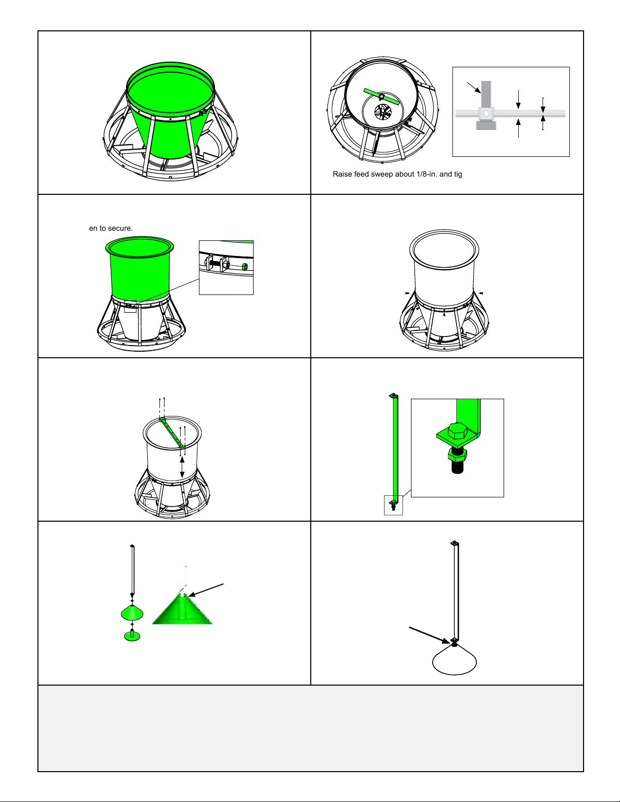
1 KF-F10002 Tolva superior
2
KF-F10007 ó
KF-F1ZP01 ó
KF-F1S003
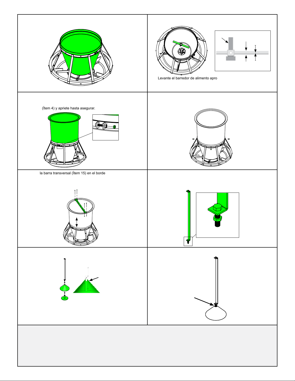
Barredor de alimento con tornillo
Barredor de alimento de zinc con tornillo
Barredor de alimento de acero inox. con tornillo
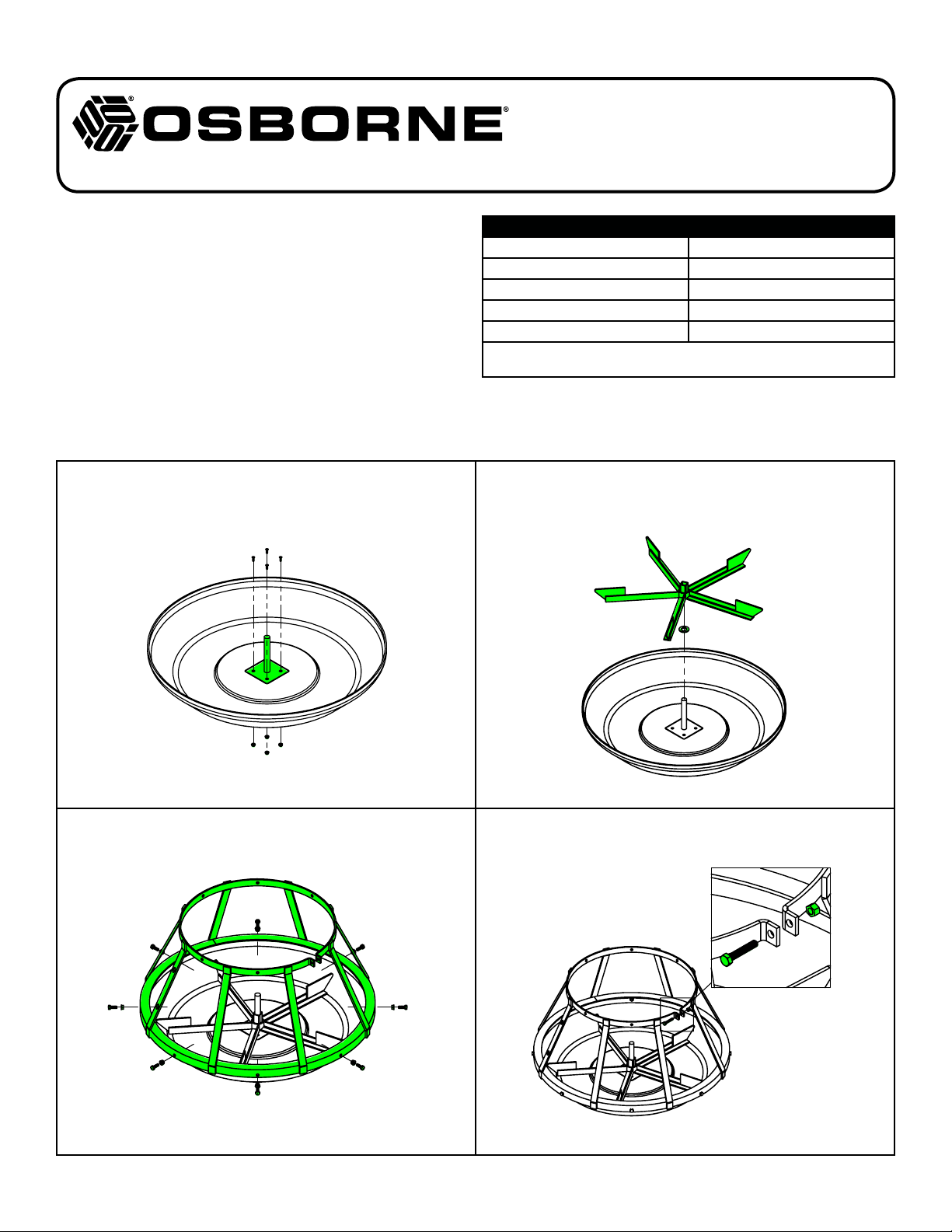
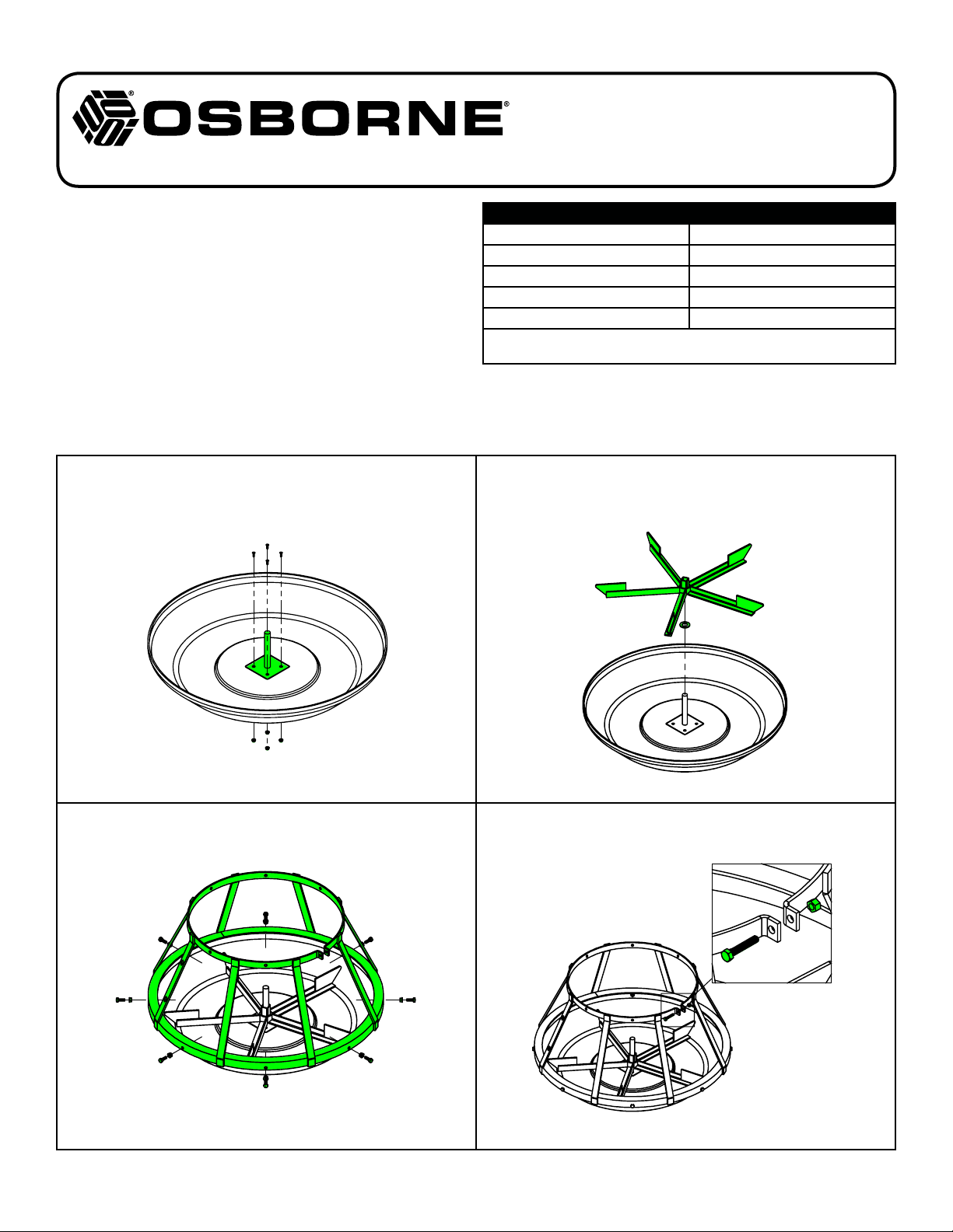
3 KF-F10001 Tolva inferior
4
RFB-2200
RFN-2100
RFN-2200
Perno de ajuste, 5/16 x 1 3/4 pulg.
Tuerca de ajuste, 5/16 pulg.
Tuerca de seguridad, 5/16 pulg.
5RFB-2050
RFN-2300
Pernos jaula divisoria, 5/16 x 7/8 pulg. (7 c/u)
Tuercas jaula divisoria, 5/16 pulg. (7 c/u)
6
KF-F10005 ó
KF-F1G001 ó
KF-F1S001
Jaula divisoria
Jaula divisoria de acero galvanizado
Jaula divisoria de acero inoxidable
7RFB-2050
RFN-2300
Pernos jaula divisoria, 5/16 x 7/8 pulg. (8 c/u)
Tuercas jaula divisoria, 5/16 pulg. (8 c/u)
8
KF-F10006 ó
KF-F1G002 ó
KF-F1S002
Rueda
Rueda de acero galvanizado
Rueda de acero inoxidable
9 RFW-7001 Golilla de rueda, 3/4 pulg.
10
KF-F1008 ó
KF-F1ZP02 ó
KF-F1S004
Eje
Eje de zinc
Eje de acero inoxidable
11 RFB-0821 Pernos del eje, 10-24 (4 c/u)
12 KF-F10003 Plato
13 RFN-0851 Tuercas del eje, 10-24 (4 c/u)
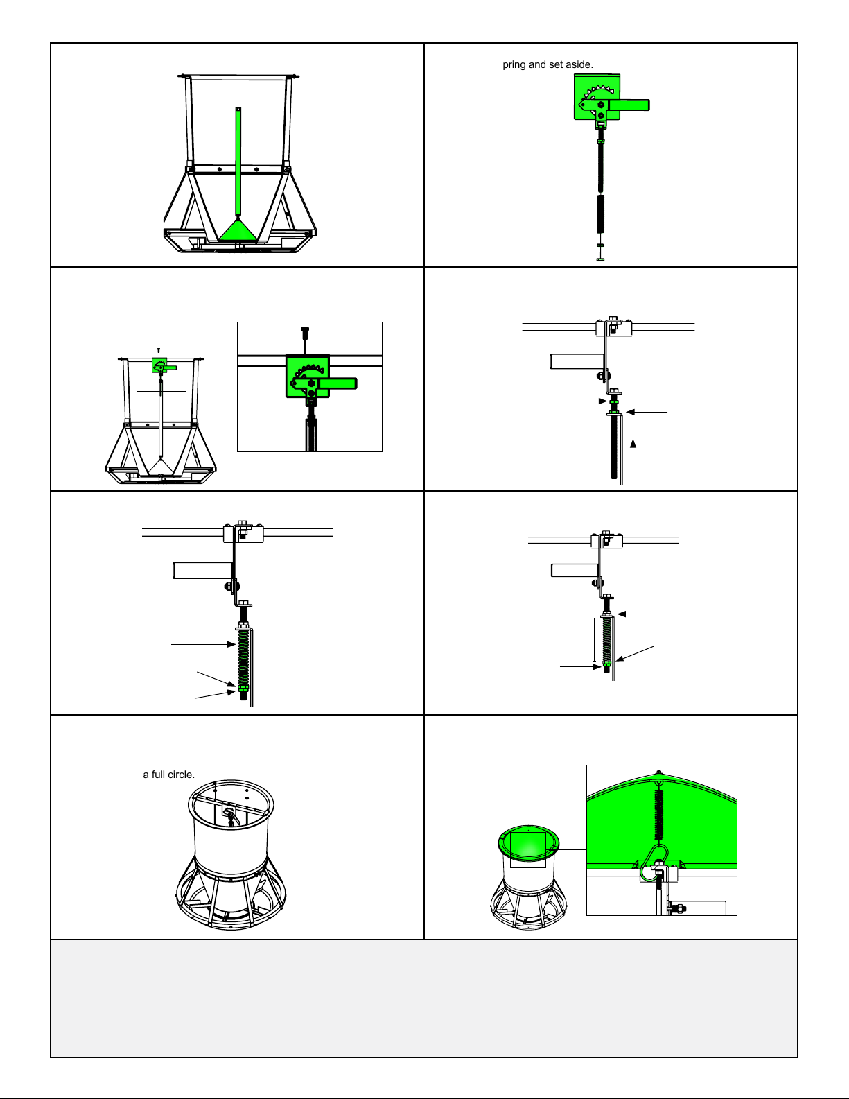
14 KF-F10022 Mecanismo de ujo de alimento
15 KF-F10011 ó
KF-F1ZP04
Barra Transversal
Barra transversal de zinc
16 RFB-0810 Pernos barra transversal, 10-24 (4 c/u)
Tuercas barra transversal, 10-24 (4 c/u)
17 RFN-0811 Barra del cono
Barra del cono de zinc
18A
18B
18C
RFB-3200
RFN-3500
RFW-2000
Perno, 3/8 x 1 1/2 pulg.
Tuerca aseg. hex. 3/8 pulg.
Golilla de soporte del cono, 5/16 pulg. (2 c/u)
19 KF-F10004 Cono
20 KF-F10009 Soporte del cono
Soporte del cono de zinc
21 FF-00RF1B ó
FF-00RF1ZP
Barra agitadora (2 c/u)
Barra agitadora de zinc (2 c/u)
22 RFN-2400
RFW-2000
Tuerca barra agitadora (2 c/u)
Golilla barra agitadora (2 c/u)
23 FF-00RF1E Soporte de ancla (3 c/u; ordenar por separado)
24 Tapa de la tolva (ordenar por separado)
Parte #
KF-N10002
KF-N10007 ó
KF-N1ZP01 ó
KF-N1S003
KF-F20005
Incluído en kit
de pernos
Incluído en kit
de pernos
KF-F20002 ó
KF-F2G001 ó
KF-F2S001
Incluído en kit
de pernos
KF-F20003 ó
KF-F2G002 ó
KF-F2S002
Kit de pernos
KF-N10008 ó
KF-N1ZP02 ó
KF-N1S004
Kit de pernos
KF-F20001
Kit de pernos
KF-F10024
KF-N10011 ó
KF-N1ZP04
Kit de pernos
KF-N10013 ó
KF-N1ZP05
Incluído en kit
de pernos
KF-N10004
KF-N10009 ó
KF-N1ZP03
FF-00RN1B ó
FF-00RN1BZP
RFN-2400
RFW-2000
FF-00RF2E
FF-00RN1L
P.O. Box 388 • Osborne, KS 67473 U.S.A.
Teléfono: 1-785-346-2192 • Fax: 1-785-346-2194
Impreso en EE.UU.
KITS DE PERNOS DE REPUESTO
KF-F10012 Kit de pernos (incluye kit de pernos de la jaula)
KF-F10013 Kit de pernos de la jaula
KF-F1S005 Kit de pernos (incluye pernos de la jaula, acero inox.)
KF-F1S006 Kit de pernos de la jaula (acero inox.)
OSBORNE BIG WHEEL®SERIE RF2
COMEDERO DE ENGORDA
LISTA DE PARTES
Accesorios adicionales, como tapas de comederos y opciones múltiples de adaptadores para rejas, están disponibles en Osborne y deben ser ordenados por separado.
1
2
3
4
5
6
7
8
9
10
11
12
13
15
16
17
21
18
18A
18B
18C
19
18C
20
23
14
22
18A
18B
19
20
18C
21
16
22
17
15
14
24
13
12
11
10
9
8
7
6
54
3
2
1
23
Table of contents
Languages:
Other Osborne Farm Equipment manuals