OSCO LA36 User manual

Oct. 2005, Rev. 12
LL
LL
LAA
AA
A3636
3636
36
INSINS
INSINS
INSTT
TT
T
ALAL
ALAL
ALLL
LL
LAA
AA
ATT
TT
TIONGUIDEIONGUIDE
IONGUIDEIONGUIDE
IONGUIDE
OPERATORSPECIALTYCOMPANY,INC.OPERATORSPECIALTYCOMPANY,INC.
OPERATORSPECIALTYCOMPANY,INC.OPERATORSPECIALTYCOMPANY,INC.
OPERATORSPECIALTYCOMPANY,INC.
CASNOVIA, MI 49318 • U.S.A.
®
OSCO REQUIRES THE USE OF CONTACT EDGES OR
PHOTOELECTRIC CONTROLS ON ALL AUTOMATIC
OR REMOTELY-CONTROLLED GATE OPERATORS.
LA36 OPERATOR INSTALLATION GUIDELA36 OPERATOR INSTALLATION GUIDE
LA36 OPERATOR INSTALLATION GUIDELA36 OPERATOR INSTALLATION GUIDE
LA36 OPERATOR INSTALLATION GUIDE
- 2 -- 2 -
- 2 -- 2 -
- 2 -
TABLEOFCONTENTSTABLEOFCONTENTS
TABLEOFCONTENTSTABLEOFCONTENTS
TABLEOFCONTENTS
PRE-INSTALLATION INFORMATION
Safety Information and Warnings ........................................................................................................................................ 3
Pre-Installation Information .................................................................................................................................................. 3
Warranty............................................................................................................................................................................... 3
INSTALLATION
Wiring Specifications ........................................................................................................................................................... 4
Post/Pillar Bracket Installation ............................................................................................................................................ 5
Gate Bracket Installation ..................................................................................................................................................... 5
Control Box Mounting .......................................................................................................................................................... 5
Gate Layout Illustration........................................................................................................................................................ 6
Limit Switch Adjustment...................................................................................................................................................... 7
CONTROL BOARD ADJUSTMENTS and ACCESSORY CONNECTIONS
Control Board Adjustments ................................................................................................................................................. 8
Terminal Connection Descriptions ....................................................................................................................................... 9
Current Sensing Adjustments ........................................................................................................................................... 10
Close Direction Current Sense Adjustment ...................................................................................................................... 10
Open Direction Current Sense Adjustment....................................................................................................................... 10
Maximum Run Timer Adjustment...................................................................................................................................... 10
Auto Close Timer Adjustment ........................................................................................................................................... 10
Battery Back-Up Charger Board Configuration ................................................................................................................. 10
Master/Slave Connection................................................................................................................................................... 10
Onboard L.E.D. Indicator Descriptions.............................................................................................................................. 11
Charger Board Sleep Mode ............................................................................................................................................... 12
Surge Protector Instructions.............................................................................................................................................. 12
Control and Accessory Connection Illustrations .......................................................................................................... 13-16
ILLUSTRATIONS
Loop Layout Illustration...................................................................................................................................................... 17
Edge Layout Illustration ..................................................................................................................................................... 18
Photo Eye Illustration ........................................................................................................................................................ 19
TROUBLESHOOTING ........................................................................................................................................................... 20
PARTS LISTS
How to Order Replacement Parts...................................................................................................................................... 20
Model LA36 Mechanical Parts Exploded View and Parts List......................................................................................... 21
Model LA36 Control Box Exploded View and Parts List .................................................................................................. 22
PREVENTATIVE MAINTENANCE ......................................................................................................................................... 23
Battery Maintenance.......................................................................................................................................................... 23
GATE OPERATOR INSTALLATION CHECKLIST ................................................................................................................ 24
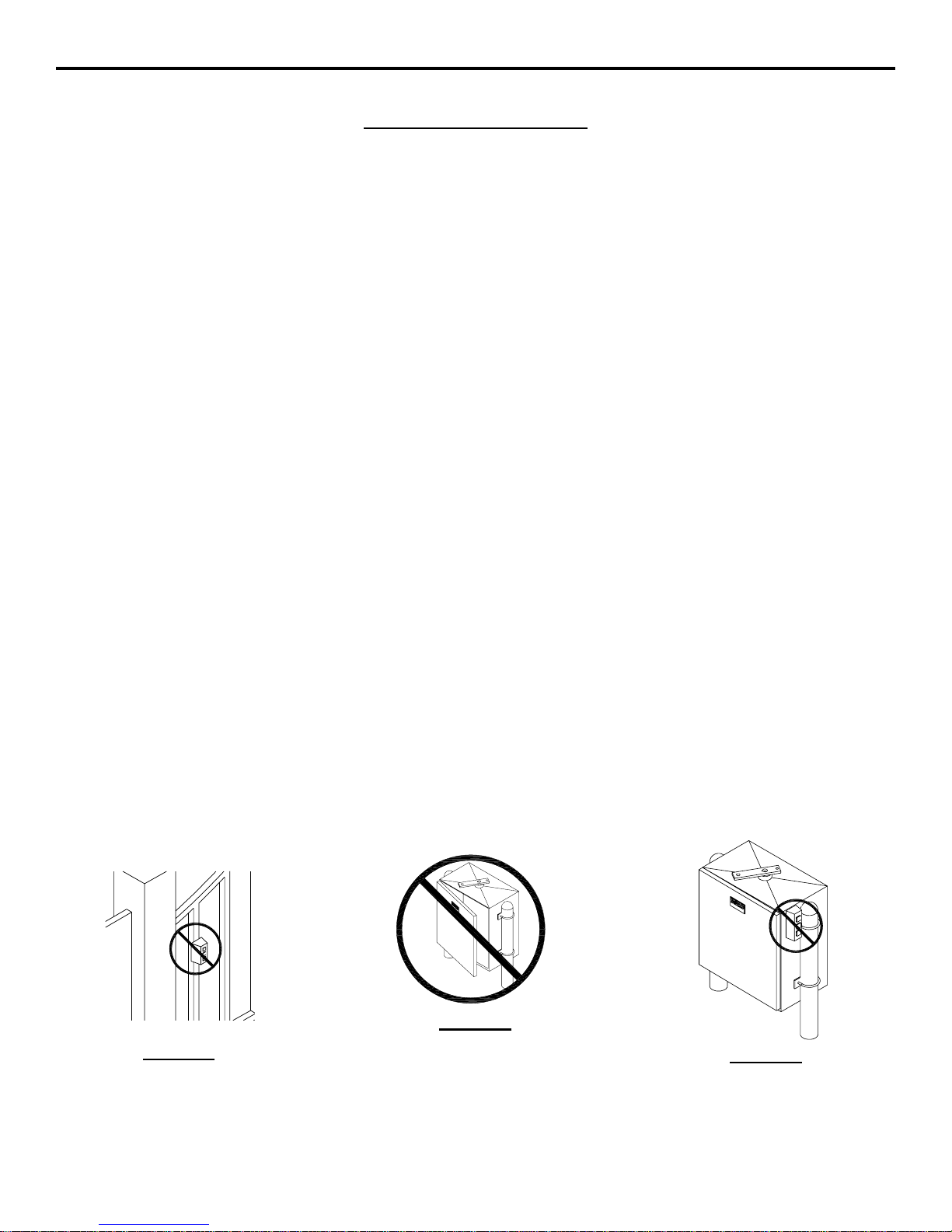
CAUTION!
DO NOT INSTALL
CONTROLSON OR
NEARTHEGATE
CAUTION!
DO NOT INSTALL
CONTROLSON
THEOPERATOR
CAUTION!
ONLYQUALIFIED SERVICE
TECHNICIANSSHOULD
WORK ON AN OSCO
SWINGGATEOPERATOR
2-03-4

LA36 OPERATOR INSTALLATION GUIDELA36 OPERATOR INSTALLATION GUIDE
LA36 OPERATOR INSTALLATION GUIDELA36 OPERATOR INSTALLATION GUIDE
LA36 OPERATOR INSTALLATION GUIDE
- 3 -- 3 -
- 3 -- 3 -
- 3 -
Read the following before beginning to install OSCO swing
gateoperators:
1. Readthe orange“SafetyInstructions” brochureenclosed
with the packet of information. If you do not have one,
pleasecallOSCOat1-800-333-1717torequestone. Read
andfollow all instructions.
2. All electrical connections to the power supply must be
made by a licensed electrician and must observe all
national and local electrical codes.
3. A separate power-disconnect switch should be located
nearthe operatorso thatprimary powercan beturned off
whennecessary.
4. Install the enclosed warning signs on both sides of the
gate. Each sign must be plainly visible from the side of
the gate on which they are mounted.
5. Never reach between, through or around the fence to
operatethe gate.
6. You must install all required safety equipment.
GATEOPERATORCLASSIFICATIONSGATEOPERATORCLASSIFICATIONS
GATEOPERATORCLASSIFICATIONSGATEOPERATORCLASSIFICATIONS
GATEOPERATORCLASSIFICATIONS
All gate operators can be divided into one of four different
classifications,depending on theirdesign and usage.
Class I Residential Vehicular Gate Operator
Avehiculargate operatorintended foruse in ahome ofone to
foursingle familydwellings,or garageor parkingarea associ-
atedwith these dwellings.
Class II Commercial / General Access Vehicular Gate
Operator
A vehicular gate operator intended for use in a commercial
location or building such as a multifamily housing unit of five
ormore singlefamily units, hotel,retail storeor other building
servicingthe generalpublic.
Class III Industrial / Limited Access Vehicular Gate
Operator
A vehicular gate operator intended for use in an industrial
location or building such as a factory or loading dock area or
otherlocation not intendedto service thegeneral public.
Class IV RestrictedAccess Vehicular Gate Operator
Avehiculargate operatorintendedfor useina guardedindus-
trial location or building such as an airport security area or
other restricted access locations not servicing the general
public,inwhich unauthorizedaccessis preventedviasupervi-
sion by security personnel.
PRE-INSTALLATIONPRE-INSTALLATION
PRE-INSTALLATIONPRE-INSTALLATION
PRE-INSTALLATION
INFORMATIONINFORMATION
INFORMATIONINFORMATION
INFORMATION
Before unpacking, inspect the carton for exterior damage. If
youfinddamage,advisethedeliverycarrierofapotentialclaim.
Inspect your package carefully. You can check your
accessory box parts with the enclosed packing slip for your
convenience.Claimsfor shortageswill behonoredfor only30
days from the date of shipment.
Before installing the operator, read this manual completely
toensure all requirementsfor properinstallation are present.
Verify that the voltage to be used matches the voltage of the
operator.
SAFETYINFORMATIONSAFETYINFORMATION
SAFETYINFORMATIONSAFETYINFORMATION
SAFETYINFORMATION
AND WARNINGSAND WARNINGS
AND WARNINGSAND WARNINGS
AND WARNINGS
IMPORTANT!!
Beforeinstallingthe gateoperator,make surethegate’sswing
is free and level throughout the entire swing path. If the gate
does not seem to operate properly, it may affect the operator
performance or greatly shorten the life of the unit. The gate
should be designed so that airflow is ample to prevent wind
resistanceand drag.
The following contact or non-contact obstruction
detection devices have been approved for use
with OSCO slide gate operators as part of a UL325
compliant installation:
ContactEdges:
MillerModels*: MG0-20,MGR-20, MGS-20,and ME-120
Photoeyes:
2520-441 MMTCModel IR-55 photoeye,165’ with
mountinghardware
2520-031 MMTC Model E3K photoeye, 28’ with
mountinghardware
*for OSCO part numbers, contact a sales representative for details
10-05-12
LA36 OPERATOR INSTALLATION GUIDELA36 OPERATOR INSTALLATION GUIDE
LA36 OPERATOR INSTALLATION GUIDELA36 OPERATOR INSTALLATION GUIDE
LA36 OPERATOR INSTALLATION GUIDE
- 4 -- 4 -
- 4 -- 4 -
- 4 -
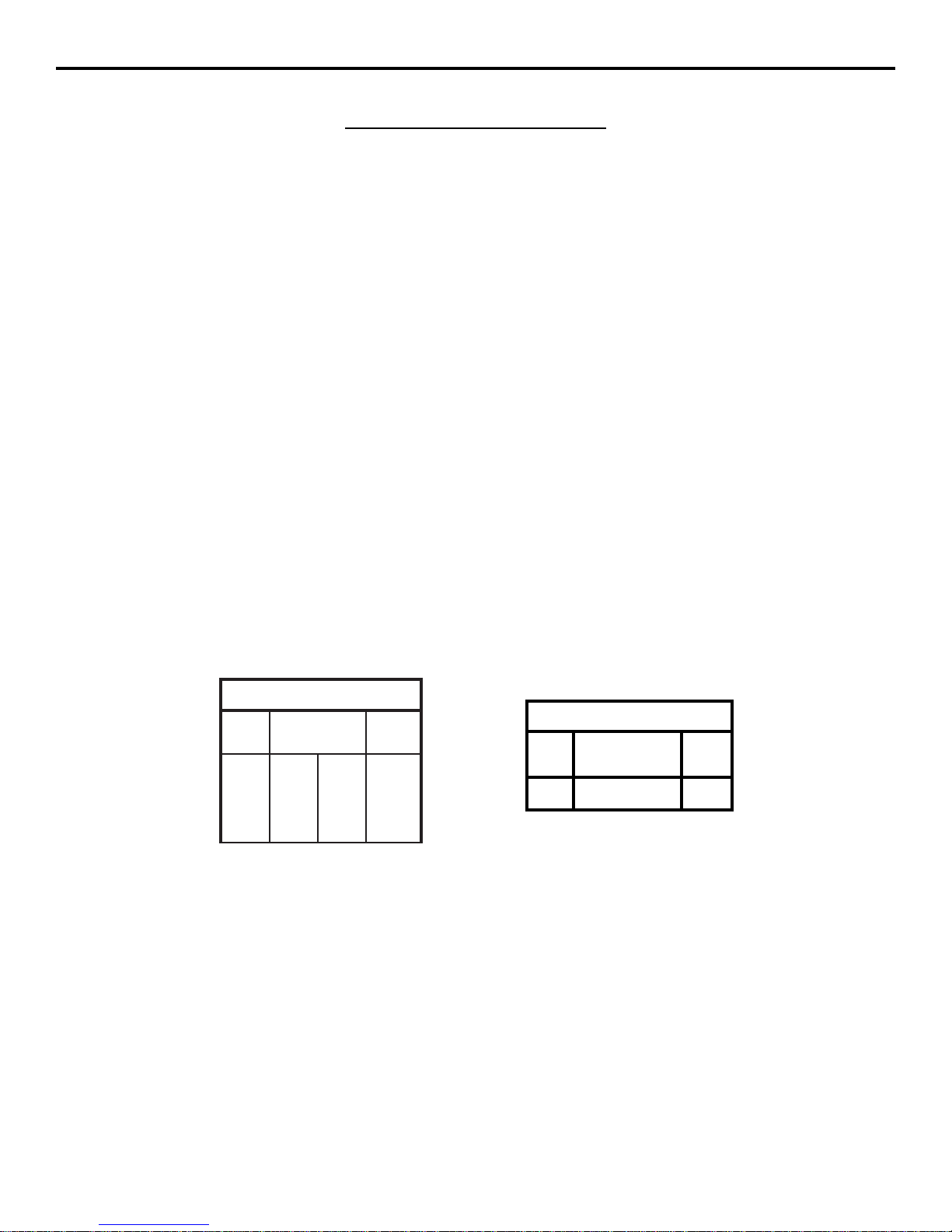
USE COPPER WIRE ONLY!
MODEL LA36MODEL LA36
MODEL LA36MODEL LA36
MODEL LA36
gniriWrewoP
stloV
PH&
ecnatsiDxaM
lauDelgniS
eriW
eguaG
V5118823
4225
4461
2162
41
21
MODEL LA36MODEL LA36
MODEL LA36MODEL LA36
MODEL LA36
ACCESSORY WIRINGACCESSORY WIRING
ACCESSORY WIRINGACCESSORY WIRING
ACCESSORY WIRING
All DC Models
24VDC
0-2000
14
Volts
Maximum
Distance (ft.)
Wire
Gauge
1. Select from the chart at the bottom of this page corre-
spondingto the model,voltage and horsepower rating of
youroperator.
2. Thedistanceshown onthe chartis measuredinfeet from
theoperatortothe powersource.DO NOTEXCEED THE
MAXIMUM DISTANCE. These calculations have been
based on standard 115V with a 10% drop allowable. If
your supply is under the standard rating, the runs listed
maybelonger thanwhat yourapplication willhandle,and
you should not run wire too near the upper end of the
chartfor the gauge ofwire you areusing.
3. When large-gauge wire is used, a separate junction box
(notsupplied)may beneededforthe operatorpowercon-
nection.
WIRINGSPECIFICATIONSWIRINGSPECIFICATIONS
WIRINGSPECIFICATIONSWIRINGSPECIFICATIONS
WIRINGSPECIFICATIONS
4. Allcontroldevices arenow24VDC,which canberuncon-
siderabledistances.
5. Wireruncalculations arebased onthe NationalElectrical
Code, Article 430 and have been carefully determined
basedon motorinrush, brakesolenoids,and operatorre-
quirements.
6. Connectpowerinaccordancewithlocalcodes.The green
ground wire must be properly connected.
7. Wire insulation must be suitable to the application.
8. Controlwiringmustberuninaseparateconduitfrompower
wiring.Runningthemtogethermaycauseinterferenceand
faulty signals in some accessories.
2-03-4
LA36 OPERATOR INSTALLATION GUIDELA36 OPERATOR INSTALLATION GUIDE
LA36 OPERATOR INSTALLATION GUIDELA36 OPERATOR INSTALLATION GUIDE
LA36 OPERATOR INSTALLATION GUIDE
- 5 -- 5 -
- 5 -- 5 -
- 5 -
CONTROLBOX MOUNTINGCONTROLBOX MOUNTING
CONTROLBOX MOUNTINGCONTROLBOX MOUNTING
CONTROLBOX MOUNTING
For dual-leaf applications, both linear drive motors will connect to a single control box. Locate the control box in the vicinity of
eitherlinear actuator motor.Mount the boxfirmly to anon-movable object.Knockouts areprovided for conduits.Do notmount
the control box where a lawn sprinkler may spray water on it.
NOTE: Wheninstalling thecable connecting theoperator to the control box,be sure toleave someslack to allowfor theswing
ofthe gate. Water tight connectors arehighly recommended.
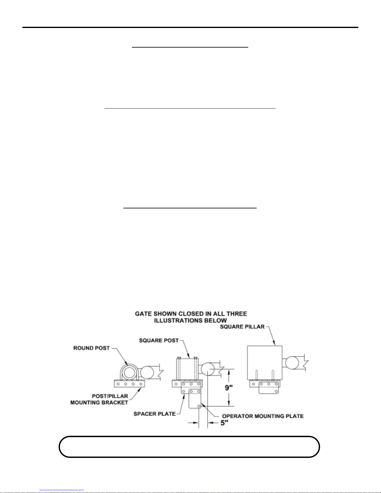
POST/PILLAR BRACKET INSTALLATIONPOST/PILLAR BRACKET INSTALLATION
POST/PILLAR BRACKET INSTALLATIONPOST/PILLAR BRACKET INSTALLATION
POST/PILLAR BRACKET INSTALLATION
Severalbrackets havebeensupplied forpost orpillar mounting.The postpillar bracket,operatormounting bracket,and spacer
plate can be combined in various configurations to fit most applications. It is very important to achieve the required mounting
locationforproper operationand toavoid premature failure.
1. Locatethe post pillarbracket verticallyapproximately halfway upfrom the groundrelative to theoverall gateheight.
2. If mounting to a round post of 4” diameter or less, use two U-bolts to attach the post/pillar bracket.
3. Ifmounting toa square post,use eitherthrough boltsor, if applicable,weld thebracket to thepost directly.Avoiddrilling into
mortarjointswherever possible.
4. When mounting to a pillar, anchor the bracket using 1/2” lag bolts and lag bolt anchors. Drill 3/4” diameter holes to a depth
of 4” using a rotary hammer percussion drill. Insert lag bolt anchors for 1/2” diameter lag bolts. Lubricate bolts before
installationand tighten inplace when done.
GATEBRACKETINSTALLATIONGATEBRACKETINSTALLATION
GATEBRACKETINSTALLATIONGATEBRACKETINSTALLATION
GATEBRACKETINSTALLATION
Referto the illustrationon thefollowing page.
1. Openthe gate toapproximately 90 to 95degrees (full open position).
2. Carefullymount the operator to the post/pillar bracket assemblyand hold the frontend of the operatorlevel and in its fully
open position.If necessary, youcan temporarilyapply powerto theoperator toopen itfully. DO NOTALLOW THE DRIVE
TUBE TO SPIN!
3. Line up the gate bracket with the linear actuator and mark the position. Clamp the bracket in place. Once its final position
is set, permanently attach the bracket.
4. Runthe operator to the fully-closed position,adjusting the closelimit as neededto achieve fulltravel. Make anymounting
changesneeded to achievefull travel withoutthe operator bindingagainst the post,gate, etc.
Thefactory suggested mountingwill use approximately 14”of stroke. Themaximum available strokefor the LA36 is18”.
ASEPARATEPEDESTRIANGATEISREQUIREDFOR ALLPEDESTRIANTRAFFIC.THISGATE
MUSTBEAMINIMUMDISTANCEOF7FEETFROMTHE VEHICULARGATEANDGATE OPERATOR
10-05-12

LA36 OPERATOR INSTALLATION GUIDELA36 OPERATOR INSTALLATION GUIDE
LA36 OPERATOR INSTALLATION GUIDELA36 OPERATOR INSTALLATION GUIDE
LA36 OPERATOR INSTALLATION GUIDE
- 6 -- 6 -
- 6 -- 6 -
- 6 -
GATELAYOUTILLUSTRATIONGATELAYOUTILLUSTRATION
GATELAYOUTILLUSTRATIONGATELAYOUTILLUSTRATION
GATELAYOUTILLUSTRATION
2-03-4

LA36 OPERATOR INSTALLATION GUIDELA36 OPERATOR INSTALLATION GUIDE
LA36 OPERATOR INSTALLATION GUIDELA36 OPERATOR INSTALLATION GUIDE
LA36 OPERATOR INSTALLATION GUIDE
- 7 -- 7 -
- 7 -- 7 -
- 7 -
LIMIT SWITCH ADJUSTMENTLIMIT SWITCH ADJUSTMENT
LIMIT SWITCH ADJUSTMENTLIMIT SWITCH ADJUSTMENT
LIMIT SWITCH ADJUSTMENT
The limit for open is adjusted by screwing the
innertubeinorout.The tubecanonlybescrewed
inabout 1/2”before bottoming out.
The limit for close isaccessedby removing the
gasketedboltinthecoupleroftherearcover.Using
astandard,1/4”-wide screwdriver,theadjustment
screw can be turned one click at a time. Each
clickadjuststheclosingpositionbyapproximately
4” for a 10-foot-wide gate. Each clockwise click
will allow the gate to swing further closed.
Fine tuning can be accomplished by turning the
tube 1/2 turns, keeping in mind that it will also
affectthe full-openposition.
WARNING!
YOU MUST TURN OFF THE POWER SWITCH
LOCATED IN THE LA36 CONTROL BOX
BEFORE ADJUSTING LIMITS OR
SERVICING THE OPERATOR.
12-04-11
DO NOT ALLOW THE DRIVE TUBE TO SPIN WHEN RUNNING!
LA36 OPERATOR INSTALLATION GUIDELA36 OPERATOR INSTALLATION GUIDE
LA36 OPERATOR INSTALLATION GUIDELA36 OPERATOR INSTALLATION GUIDE
LA36 OPERATOR INSTALLATION GUIDE
- 8 -- 8 -
- 8 -- 8 -
- 8 -
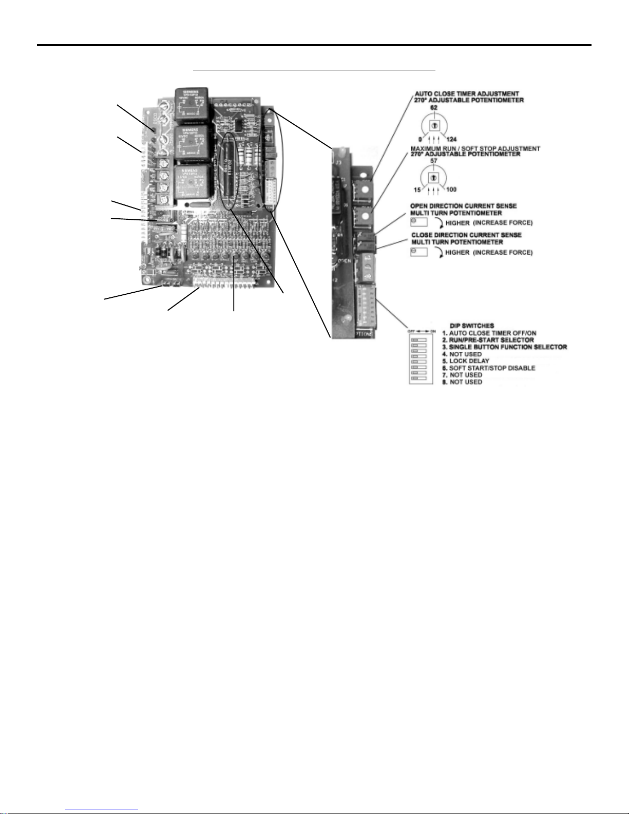
Auto Close Timer Adjustment: This 270-degree adjustable potentiometer will signal the operator to close automatically,
providednoopen, reversingorobstruction signalsare presentfromthe fully-openposition.This timerisadjustable from0 to 124
seconds. This feature is turned on or off using dip switch #1.
Maximum Run Timer Adjustment: This 270-degree adjustable potentiometer sets the amount of full speed run time for the
operator, aswell asthe maximumrun time.Thereshould be approximately threeseconds ofslow speedtravel beforereaching
the end of travel. Maximum run is set automatically as 10 seconds longer than the length of time at full speed.
Open Direction Current Sense Adjustment: This multi-turn potentiometer is used to calibrate the built-in current sensing
featurefor detection of obstructions whilerunning in theopen direction.
Close Direction Current Sense Adjustment: This multi-turn potentiometer is used to calibrate the built in current sensing
featurefor detection ofobstructions while runningin the closeddirection.
Dip Switches:
#1 This switch turns the auto close timer off/on.
#2 This switch is used in conjunction with alarms and flashing lights that may be added to the operator. When the switch is
inthe ON position, thesedevices will startapproximately two secondsprior to theoperator starting. Inthe OFF position,
thedevices will onlywork while the operatoris running.
#3 This switch is used in conjunction with single-button controls and radio receivers. In the ON position, successive inputs
will cause signals in the order of OPEN-STOP-CLOSE-STOP. In the OFF position, inputs will cause an OPEN signal
unless the gate is fully open, in which case it will signal CLOSE.
#4 Not used at this time.
#5 When turned ON, this switch will allow a one-second delay for solenoid locks to unlock before the motor starts.
#6 WhenturnedON, thisswitch disablesthe soft start/stopfeature. Ifthe switchis inthe OFFpositionand thesoft start/stop
isn’tnoticeable, remove one of the twoR2 resistors.
#7 Not used at this time.
#8 Not used at this time. Set to OFF.
CONTROLBOARD ADJUSTMENTSCONTROLBOARD ADJUSTMENTS
CONTROLBOARD ADJUSTMENTSCONTROLBOARD ADJUSTMENTS
CONTROLBOARD ADJUSTMENTS
12-04-11
NOTE:DONOTFORCE270-DEGREEPOTENTIOMETERS
BEYONDTHEIRNORMALRANGEOFMOTION
ORDAMAGEMAYRESULT!
Control Board
with DC
Motor Board
DIAGNOSTIC
L.E.D.s
TERMINAL STRIP #2
CONNECTOR
TERMINAL STRIP #1
CONNECTOR
LIMIT SWITCH
CONNECTOR
LIMIT SWITCH
L.E.D.s
3A Fuse
2A Fuse SOFT
START/STOP
RESISTOR
R2
(1 of 2 shown)

LA36 OPERATOR INSTALLATION GUIDELA36 OPERATOR INSTALLATION GUIDE
LA36 OPERATOR INSTALLATION GUIDELA36 OPERATOR INSTALLATION GUIDE
LA36 OPERATOR INSTALLATION GUIDE
- 9 -- 9 -
- 9 -- 9 -
- 9 -
You must follow all required safety precautions and instructions at all times. Review the safety brochure
included with the operator. If any pages are missing or unreadable, contact OSCO at 1-800-333-1717 to request
additional copies.
Never connect a button station within reach of the gate or on the side of the gate operator or operator
control box.
Do not adjust the circuit board current sensing feature too high. It should be adjusted high enough to keep the
gate from falsely triggering the sensing, but no higher than necessary for the gate to operate. Do not defeat the
purpose of this function!
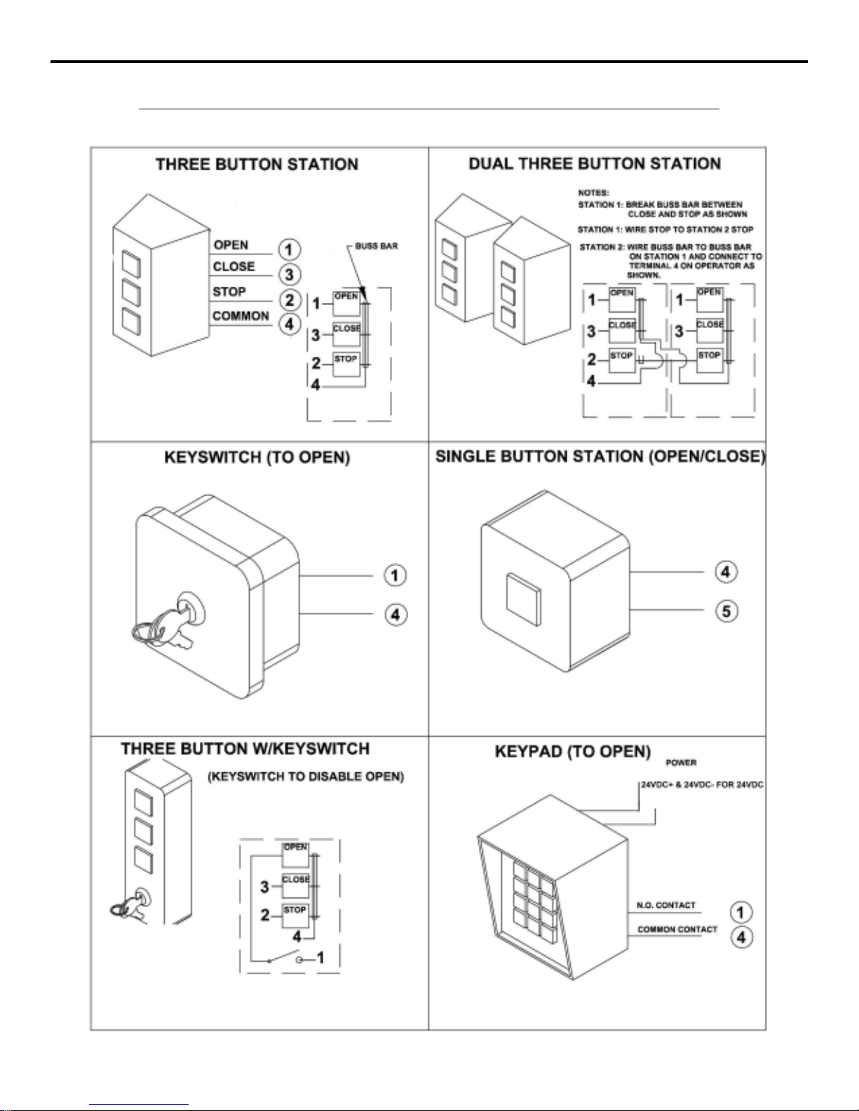
TERMINALCONNECTIONDESCRIPTIONSTERMINALCONNECTIONDESCRIPTIONS
TERMINALCONNECTIONDESCRIPTIONSTERMINALCONNECTIONDESCRIPTIONS
TERMINALCONNECTIONDESCRIPTIONS
TERMINALS FUNCTION DESCRIPTIONOF FUNCTION
24VDC+ 24VDC Providesfused 24VoltDCpower for accessories.
24VDC- COMM.
1 & 4 OPEN Opensthe operator.Several accessories suchas button stations,keypads, trans-
mitters and card readers can be wired to open.
3 & 4 CLOSE Closes the operator. Use caution when wiring accessories to these terminals.
The gate must be clearly visible from the location of any accessories wired
to close.
4 & 5 SINGLE-BUTTON Performs the single-button function which will alternate between open and close
or open, stop and close - depending on dip switch #3. (See page 8for details.)
2 & 4 STOP Stops the operator. If no stop button is used, a jumper is required across 2&4.
4 & 6 REVERSE Thisfunction will cause a reversal when the gate istraveling closed and willtravel
back to the fully open position. Loop detectors are often wired for reverse.
4 & 50 OPEN This function works only while the operator is opening. Any signal to this function
will cause the gate to stop, reverse a short distance, and then stop again. At this
time the auto close timer is disabled, and a renewed input will be required to start
the gate again. Should the gate be restarted and the signal occur again prior to
reaching a limit, the gate will stop again, and this time will sound the emergency
alarm and lock out.
4 & 51 CLOSE This functionworks exactlylike the OPENOBSTRUCTION, except thatit will only
work in the closing direction.
4 & 11 SHADOW/HOLD Thisfunction will keepthe gate inits fullyopen position whilethe signal ispresent.
This is typically used with a loop and loop detector to keep a large swing gate
open while vehicular traffic is passing through.
24VDC+& 60 RUN/PRE-START A24VoltDC devicesuch asa strobelight oralarm canbe wired to these terminals.
Depending on dip switch #2, these devices will either begin three seconds before
the operator starts, or only while the motor is running. (See page 8 for details.)
OBSTRUCTION
OBSTRUCTION
12-04-11

LA36 OPERATOR INSTALLATION GUIDELA36 OPERATOR INSTALLATION GUIDE
LA36 OPERATOR INSTALLATION GUIDELA36 OPERATOR INSTALLATION GUIDE
LA36 OPERATOR INSTALLATION GUIDE
- 10 -- 10 -
- 10 -- 10 -
- 10 -
CURRENTSENSING ADJUSTMENTSCURRENTSENSING ADJUSTMENTS
CURRENTSENSING ADJUSTMENTSCURRENTSENSING ADJUSTMENTS
CURRENTSENSING ADJUSTMENTS
Because gates vary in construction and may have different force requirements in the open and close directions to move, the
OSCO control board has separate Multi-turn potentiometers for adjusting in both directions independently. The adjustment
should be set light enough to maintain minimal force (40 lbs.) should an obstruction occur, but high enough to keep the gate
movingunder normalconditionswithout interruption.
Priorto adjustingthe operatorcurrent sensingfunctions, makesure the gatemoves freelyin bothdirections. Abadly alignedor
poorlymaintained gatemay causefalse triggeringof the currentsensor. Referto page8when following the instructionsbelow.
Afactory adjustmenttool hasbeen supplied tomake theseadjustments easier.Thistool canbe foundin theinformationpacket.
CLOSEDIRECTION CURRENTSENSEADJUSTMENTCLOSEDIRECTION CURRENTSENSEADJUSTMENT
CLOSEDIRECTION CURRENTSENSEADJUSTMENTCLOSEDIRECTION CURRENTSENSEADJUSTMENT
CLOSEDIRECTION CURRENTSENSEADJUSTMENT
When the gate operator leaves the factory, it has been preset for a relatively light gate function and will require additional
adjustment.Begin by starting the gategoing closed. If the operatorstops and reverses, turn the close direction potentiometer
(see page 8) one turn higher, press the STOP button, and try again. Repeat this process until the gate no longer causes false
trippingof thecurrent sensor.Note that eachtime thegate operatorreverses, theSTOP buttonmustbe pressed.Next, turn the
close direction potentiometer lower slowly while the operator is running the gate closed until the gate operator stops and
reversesagain. From thispoint, turn the close direction potentiometer higherby 1 1/2turns. Additional adjustmentby 1/2-turn
increments may be necessary.
OPENDIRECTION CURRENTSENSE ADJUSTMENTOPENDIRECTION CURRENTSENSE ADJUSTMENT
OPENDIRECTION CURRENTSENSE ADJUSTMENTOPENDIRECTION CURRENTSENSE ADJUSTMENT
OPENDIRECTION CURRENTSENSE ADJUSTMENT
Repeatthe sameprocess withthe opendirection potentiometer whilerunning thegate inthe opendirection. Once this is done,
run the gate through several complete cycles and make sure the gate does not false trip in either direction.
MAXIMUM RUN TIMER ADJUSTMENTMAXIMUM RUN TIMER ADJUSTMENT
MAXIMUM RUN TIMER ADJUSTMENTMAXIMUM RUN TIMER ADJUSTMENT
MAXIMUM RUN TIMER ADJUSTMENT
This adjustable potentiometer sets the full speed run time for the
operator, as well as the maximum run time. There should be
approximately three seconds of slow speed travel before reach-
ing the end of travel. Maximum run is set automatically as ten
seconds longer than the length of time at full speed. See page 8
for details.
AUTO CLOSE TIMER ADJUSTMENTAUTO CLOSE TIMER ADJUSTMENT
AUTO CLOSE TIMER ADJUSTMENTAUTO CLOSE TIMER ADJUSTMENT
AUTO CLOSE TIMER ADJUSTMENT
This adjustable potentiometer sets the length of time which
elapses before the gate operator automatically closes the gate,
from the fully open position, provided no open, reversing, or ob-
struction signals are present. This feature can be turned on or off
via dip switch selection. See page 8for details. Do not use the
auto close timer without an appropriate reversing device in-
stalled!
MASTER/SLAVE CONNECTIONMASTER/SLAVE CONNECTION
MASTER/SLAVE CONNECTIONMASTER/SLAVE CONNECTION
MASTER/SLAVE CONNECTION
Wire the black and red wires of both operators to M1 and M2 on
the motor board.
BATTERYBACK-UPBATTERYBACK-UP
BATTERYBACK-UPBATTERYBACK-UP
BATTERYBACK-UP
FOR DC MODELS ONLYFOR DC MODELS ONLY
FOR DC MODELS ONLYFOR DC MODELS ONLY
FOR DC MODELS ONLY
CHARGERBOARDCONFIGURATIONCHARGERBOARDCONFIGURATION
CHARGERBOARDCONFIGURATIONCHARGERBOARDCONFIGURATION
CHARGERBOARDCONFIGURATION
ForModelLA36,thevoltage monitor selector switch must be left in
the RUN position to function properly. If AC power is lost, it will
allow the operator to continue to function until the batteries have
droppedto17volts.Whenthebatteries have reached 17 volts, the
operatorwillopenand shut down until the batteriesarerecharged
to24voltsfromeitherreturnofpower,solarpanels,or by installing
fresh,fullychargedbatteries.(You mustturnoff thepowerswitch
beforechangingbatteries if you choose toswapthem out!)
VOLTAGE MONITORSHOWN
ABOVEINTHERUNPOSITION
Multi-turn Potentiometer
Remember it is important not to set the adjustment
too high! Doing so will defeat the purpose of the cur-
rent sensing as an obstruction detecting feature.
12-04-11

LA36 OPERATOR INSTALLATION GUIDELA36 OPERATOR INSTALLATION GUIDE
LA36 OPERATOR INSTALLATION GUIDELA36 OPERATOR INSTALLATION GUIDE
LA36 OPERATOR INSTALLATION GUIDE
- 11 -- 11 -
- 11 -- 11 -
- 11 -
ONBOARDL.E.D.INDICATORDESCRIPTIONSONBOARDL.E.D.INDICATORDESCRIPTIONS
ONBOARDL.E.D.INDICATORDESCRIPTIONSONBOARDL.E.D.INDICATORDESCRIPTIONS
ONBOARDL.E.D.INDICATORDESCRIPTIONS
CONTROLBOARD L.E.D. INDICATORS:
OPEN This indicator is lit when an open signal is present. This signal can come from such devices as button
stations, radio receivers, keypads and telephone entry systems.
CLOSE This indicator is lit when a closed signal is present. This signal typically comes from three-button stations.
STOP This indicator is lit when there is a break in the stop circuit. Make sure there is a stop button wired in and
workingproperly.
SINGLE This indicator is lit when a signal from a single-button station or radio receiver is present.
CLOSEOBST Thisindicator islit whenaclose obstruction signal ispresent. Thissignal cancomefrom edgesand photo
eyes which have been wired to the close obstruction inputs.
OPENOBST This indicator is lit when an open obstruction signal is present. This signal can come from edges and
photoeyes which havebeen wired tothe open obstructioninputs.
SAFETYLOOP This indicator is lit when a reversing signal is present. This signal is generated by a loop detector wired to
the safety loop terminals.
SHADOWLOOP This indicator islit when a shadow/hold open signal is present. Thissignal is generated by aloop detector
wiredto the shadowloop terminals.
These indicators are not used and will be lit at all times.
These indicators are not used and will be lit at all times.
MOTORBOARDL.E.D. INDICATORS:
NONLABELED One of thesetwo indicators willbe lit whenthe motor isrunning the gateopen, and theother is litwhen the
motor is running the gate closed.
BRAKEREL. This indicator is lit when the operator is running at full speed.
DCOPERATORS ONLY:
DCPOWER Indicates theoperator has power to operate. This indicator flashes when in sleep mode.
BATTERY
CHARGING Indicatesbatteries arebeing charged.
OPENGATE Operator is in open then lockout stage.
POWER
LOCKOUT Flashes when controls/motor are in lockout mode.
LSC-1
LSC-2
LSO-1
LSO-2
12-04-11

LA36 OPERATOR INSTALLATION GUIDELA36 OPERATOR INSTALLATION GUIDE
LA36 OPERATOR INSTALLATION GUIDELA36 OPERATOR INSTALLATION GUIDE
LA36 OPERATOR INSTALLATION GUIDE
- 12 -- 12 -
- 12 -- 12 -
- 12 -
CHARGERBOARDSLEEP MODECHARGERBOARDSLEEP MODE
CHARGERBOARDSLEEP MODECHARGERBOARDSLEEP MODE
CHARGERBOARDSLEEP MODE
When primary AC power is not available, the operator will continue to
operate in battery only mode if the charger board is set in its RUN mode
(see Battery Backup Charger Configuration). Accessories wired into
the operator will continue to draw power, even when the operator is not
openingor closing the gate. Thiscan dramatically reduce the amountof
standbytime availablefrom the batteries.
To extend the available standby time, the charger board has a “sleep”
mode feature which will turn off power to all controls except for any that
arewiredaccordingtotheschematicsbelow.Byremovingtheblackjumper
cap JP1 located in the upper right hand corner of the charger board this
feature can be enabled. In the absence of incoming power sufficient to
change the batteries and operate the controls, the control power will be
shutoffafter15 minutesof inactivity.This will removepower toall acces-
sories except those wired as shown below. Those wired as shown will
continueto havepower atall timesand will upon activation generatefirst
a“wake” signal thatwill powerall controlsbackup, andthen createeither
anopen signal orsingle buttonsignal, dependingonhow thewire jumper
shownbelow is connected.
OPEN
TERMINAL WAKE
TERMINAL
JP1
JUMPERCAP
CHARGERBOARD
SURGEPROTECTORINSTRUCTIONSSURGEPROTECTORINSTRUCTIONS
SURGEPROTECTORINSTRUCTIONSSURGEPROTECTORINSTRUCTIONS
SURGEPROTECTORINSTRUCTIONS
The optional surge protector should be connected
to any inputs that have an accessory connected to
it. This includes the 3-button station, so it must be
connected to 1, 2A and 3 in all cases. The green
wire connected to ground, which is electrically the
same as terminal 4. The red wires connect to
terminals 2A and 24VDC+. This will cause the
2 amp fuse to blow if this section of the module
becomes shorted. With any of the other inputs
connectedto the surge protector, if theirprotection
linebecomes shorteddueto asurge overthe rating
of the module, the corresponding LED on the main
board will remain lit, causing a constant signal to
the controller. If this is found, please replace the
entiresurge protector with a newunit.
Do not simply unhook the shorted wire, as this
removesthe protection from the circuit that was
saved by the protector in the first place!
12-04-11
LA36 OPERATOR INSTALLATION GUIDELA36 OPERATOR INSTALLATION GUIDE
LA36 OPERATOR INSTALLATION GUIDELA36 OPERATOR INSTALLATION GUIDE
LA36 OPERATOR INSTALLATION GUIDE
- 13 -- 13 -
- 13 -- 13 -
- 13 -
CONTROL and ACCESSORY CONNECTION ILLUSTRATIONSCONTROL and ACCESSORY CONNECTION ILLUSTRATIONS
CONTROL and ACCESSORY CONNECTION ILLUSTRATIONSCONTROL and ACCESSORY CONNECTION ILLUSTRATIONS
CONTROL and ACCESSORY CONNECTION ILLUSTRATIONS
10-02-3

LA36 OPERATOR INSTALLATION GUIDELA36 OPERATOR INSTALLATION GUIDE
LA36 OPERATOR INSTALLATION GUIDELA36 OPERATOR INSTALLATION GUIDE
LA36 OPERATOR INSTALLATION GUIDE
- 14 -- 14 -
- 14 -- 14 -
- 14 -
CONTROL and ACCESSORY CONNECTION ILLUSTRATIONSCONTROL and ACCESSORY CONNECTION ILLUSTRATIONS
CONTROL and ACCESSORY CONNECTION ILLUSTRATIONSCONTROL and ACCESSORY CONNECTION ILLUSTRATIONS
CONTROL and ACCESSORY CONNECTION ILLUSTRATIONS
5-04-9

LA36 OPERATOR INSTALLATION GUIDELA36 OPERATOR INSTALLATION GUIDE
LA36 OPERATOR INSTALLATION GUIDELA36 OPERATOR INSTALLATION GUIDE
LA36 OPERATOR INSTALLATION GUIDE
- 15 -- 15 -
- 15 -- 15 -
- 15 -
OSCO CONTROL and ACCESSORY CONNECTION ILLUSTRATIONSOSCO CONTROL and ACCESSORY CONNECTION ILLUSTRATIONS
OSCO CONTROL and ACCESSORY CONNECTION ILLUSTRATIONSOSCO CONTROL and ACCESSORY CONNECTION ILLUSTRATIONS
OSCO CONTROL and ACCESSORY CONNECTION ILLUSTRATIONS
2-03-4

LA36 OPERATOR INSTALLATION GUIDELA36 OPERATOR INSTALLATION GUIDE
LA36 OPERATOR INSTALLATION GUIDELA36 OPERATOR INSTALLATION GUIDE
LA36 OPERATOR INSTALLATION GUIDE
- 16 -- 16 -
- 16 -- 16 -
- 16 -
CONTROL and ACCESSORY CONNECTION ILLUSTRATIONSCONTROL and ACCESSORY CONNECTION ILLUSTRATIONS
CONTROL and ACCESSORY CONNECTION ILLUSTRATIONSCONTROL and ACCESSORY CONNECTION ILLUSTRATIONS
CONTROL and ACCESSORY CONNECTION ILLUSTRATIONS
12-04-11

LA36 OPERATOR INSTALLATION GUIDELA36 OPERATOR INSTALLATION GUIDE
LA36 OPERATOR INSTALLATION GUIDELA36 OPERATOR INSTALLATION GUIDE
LA36 OPERATOR INSTALLATION GUIDE
- 17 -- 17 -
- 17 -- 17 -
- 17 -
LOOPLAYOUTILLUSTRATIONLOOPLAYOUTILLUSTRATION
LOOPLAYOUTILLUSTRATIONLOOPLAYOUTILLUSTRATION
LOOPLAYOUTILLUSTRATION
Referto Connection Descriptionson page 9and Loop AccessoryConnections on page16 for additionaldetails.
2-03-4

LA36 OPERATOR INSTALLATION GUIDELA36 OPERATOR INSTALLATION GUIDE
LA36 OPERATOR INSTALLATION GUIDELA36 OPERATOR INSTALLATION GUIDE
LA36 OPERATOR INSTALLATION GUIDE
- 18 -- 18 -
- 18 -- 18 -
- 18 -
EDGE LAYOUT ILLUSTRATIONEDGE LAYOUT ILLUSTRATION
EDGE LAYOUT ILLUSTRATIONEDGE LAYOUT ILLUSTRATION
EDGE LAYOUT ILLUSTRATION
Referto Connection Descriptionson page 9 and ContactEdge Connections onpage 15 foradditional details.
2-03-4
LA36 OPERATOR INSTALLATION GUIDELA36 OPERATOR INSTALLATION GUIDE
LA36 OPERATOR INSTALLATION GUIDELA36 OPERATOR INSTALLATION GUIDE
LA36 OPERATOR INSTALLATION GUIDE
- 19 -- 19 -
- 19 -- 19 -
- 19 -
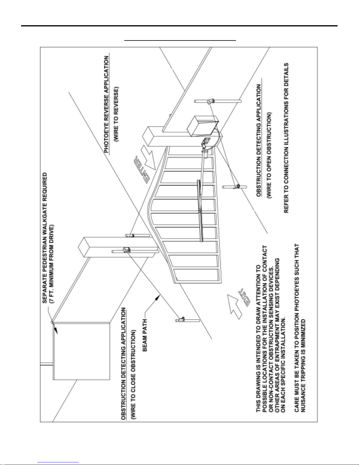
PHOTO EYE ILLUSTRATIONPHOTO EYE ILLUSTRATION
PHOTO EYE ILLUSTRATIONPHOTO EYE ILLUSTRATION
PHOTO EYE ILLUSTRATION
Referto Connection Descriptionson page 9and Photoeye AccessoryConnections on page15 for additional details.
2-03-4

LA36 OPERATOR INSTALLATION GUIDELA36 OPERATOR INSTALLATION GUIDE
LA36 OPERATOR INSTALLATION GUIDELA36 OPERATOR INSTALLATION GUIDE
LA36 OPERATOR INSTALLATION GUIDE
- 20 -- 20 -
- 20 -- 20 -
- 20 -
TROUBLESHOOTINGTROUBLESHOOTING
TROUBLESHOOTINGTROUBLESHOOTING
TROUBLESHOOTING
Operatorfails to start:
A. Makesure youhavepower atthe master distributionpanel
andthat the powerhas not beenturned off.
B. The3-amp fuseonthe controlboard or chargerboard may
haveblown.Replace thefuse(refer tocontrolbox partslist
onpage 22.
Motor operates, but gate does not move:
A. Makesure all mountinghardware is stillattached andthat
all fasteners are tight.
B. Check that the actuator cylinder is moving. If it isn’t, the
gearsin thedrive mayhave stripped.
Motor sounds like it is working harder than normal:
A. Make sure the gate is moving freely and without binding
throughoutits entiretravel.
Gate stopping part way open or closed
(but no visible obstruction):
A. The control board may have received a false obstruction
input triggered by current sensing set too low. Make sure
the gate moves freely through its entire travel before ad-
justing the current sensing.
B. The maximum run timer may have counted down and
expired. This can be caused by having the timer set too
low. Whenthe timer expires, thegate stopsand an alarm
willsound.
C. An obstruction signal from an accessory wired to the ob-
structioninput may havetriggered falsely.Check thecon-
trol board for lit L.E.D. indicators for any of the following
inputs: safety, shadow, open obstruction, close obstruc-
tion, stop, etc. If any are lit when the operator should be
running, remove all devices hooked to that function and
hookthem uponeat atime andtry torunthe operatoruntil
theproblemdevice isfound.Refer to page11 for detailson
thecontrol board indicators.
Gatestaying open withautomatic system:
A. Ifthere arevehicledetectors inyourmachinewhich areset
upfor reverse,one ofyour loops orloop detectorsmay be
sending a false signal. Disconnect the wire harness and
tryrunning theoperator.
B. An opening or reversing device may be stuck or malfunc-
tioning. Try disconnecting these devices and hook them
backup oneata timeand tryrunning theoperator untilthe
malfunctioningdeviceis found.
HOW TO ORDER REPLACEMENT PARTS
Use the part numbers listed on the following pages. Contact your local OSCO dealer or distributor to order parts.
1. Supplythe modelnumber and serialnumber ofyour operator.
2. Specifythe quantity ofpieces needed andorder by part numberand name ofpart.
3. State whether to ship by freight, truck, parcel post, UPS or air express.
4. Statewhether transportation chargesare to beprepaid or collect.
5. Specify name and address of person or company to whom parts are to be shipped.
6. Specify name and address of person or company to whom invoice is to be sent.
WARNING!
YOU MUST TURN OFF THE POWER SWITCH
LOCATED IN THE LA36 CONTROL BOX BEFORE
SERVICING THE GATE OR GATE OPERATOR!
KEEP CLEAR OF THE GATE DURING OPERATION!
12-04-11
Table of contents
Other OSCO Gate Opener manuals


Popular Gate Opener manuals by other brands


Novoferm tormatic
Novoferm tormatic Novomatic 200 Installation, operating and maintenance instructions

CAME
CAME U 8700 installation guide

BFT
BFT PHOBOS N BT Installer's reference guide

Nice
Nice MC824L quick guide

RIB
RIB PRINCE 24V Important Safety Instructions For The Installation

Centurion
Centurion Auto-Mate installation manual


