OSEE HDC6831N User manual

HDC6831N HD-SDI Downconverter
/Demultiplexer /Audio and Video Monitor
USER MANUAL


Product Information
Model: HDC6831N HD-SDI Downconverter/Demultiplexer /Audio and
Video Monitor
Version: V010003
Release Date: June 7th, 2011
Company
OSEE TECHNOLOGY CO., LTD.
Contact Information
Address: No.22 Building, No.68 zone, Beiqing Road, Haidian District,
Beijing, China
Post Code: 100094
Tel: (+86) 010-62434168
Fax: (+86) 010-62434169
Web: http://www.osee-dig.com/
E-mail: [email protected]

Contents
Chapter 1 Introduction................................................................1
1.1 Overview ............................................................................................................. 1
1.2 Features................................................................................................................ 1
1.3 Module Descriptions............................................................................................ 3
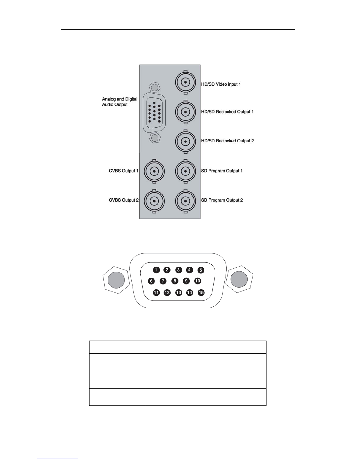
1.3.1 Back Connector............................................................................................................3
1.3.2 Back Connector of HDC6831N....................................................................................4
1.3.3 Signal Flow..................................................................................................................6
Chapter 2 Installation..................................................................7
2.1 Overview ............................................................................................................. 7
2.2 Maximum Power Ratings for Frame ................................................................... 7
2.3 Unpacking the Module ........................................................................................ 7
2.3.1 Preparing the Product for Installation.........................................................................7
2.3.2 Check the Packing List.................................................................................................8
2.4 Installing the Module........................................................................................... 8
2.5 Making the Connections...................................................................................... 9
2.6 Removing the Module ......................................................................................... 9
Chapter 3 Operation and Control .............................................10
3.1 Switches............................................................................................................. 10
3.2 Bank 0 Function Setting .....................................................................................11
3.3 Bank 1 Function Setting .................................................................................... 12
3.4 Bank 2 Function Setting .................................................................................... 14
3.5 LED Indicator .................................................................................................... 15
3.6 Setting Jumper ................................................................................................... 15
Chapter 4 Specifications...........................................................16
4.1 SD/HD-SDI Video Input ................................................................................... 16
4.2 SD/HD-SDI Reclocked Video Output............................................................... 17
4.3 SD-SDI Video Output........................................................................................ 17
4.4 Analog Composite Video Output....................................................................... 18
4.5 Balanced AES Audio Output ............................................................................. 18
4.6 Unbalanced AES Audio Output......................................................................... 19
4.7 Analog Audio Output......................................................................................... 19

Chapter 1 Introduction
HDC6831N HD-SDI Downconverter / Demultiplexer /Audio and Video Monitor 1
Chapter 1 Introduction
1.1 Overview
In the manual, HDC6831N HD-SDI Downconverter / Demultiplexer /Audio and Video Monitor is
introduced. The modules can be installed in 6800N series frame.
HDC6831N is a high definition downconverter from HD-SDI to SD-SDI or analog composite, in
addition, it also support SD-SDI to analog composite downconversion.
HDC6831N is a multiplexer with 2-pair AES/EBU digital audio outputs and 4-channel analog audio
outputs. The module characterizes 8-channel audio meter indication which can be overlapped on
CVBS output or SD-SDI output.
The module can display OSD menu, time code and standards of input and output, and can monitor
8-channel audio signal. Furthermore, it supports SNMP control and status indication.
Tab. 1-1 Description of input and output of HDC6831N
Module Input Output
HDC6831N
1-channel
HD/SD-SDI Video
input
2-channel reclocked HD/SD-SDI loop outputs
2-channel SD-SDI outputs with audio re-inserting and
video processing *
2-channel CVBS outputs with video processing *
4-channel analog audio outputs
2-pair AES/EBU digital audio outputs, balanced or
unbalanced
* video processing means users set the parameters in order to add OSD menu, time code,
standards of input and output and 8-channel audio meter into video.
1.2 Features
The HDC6831N offers the following features:
Auto-detect HD-SDI or SD-SDI input, and convert it into SD-SDI and CVBS outputs with the
approximate frequency
Support several standard conversion of 1080I,1080P,720P,1035I,576I,480I. For more
information, please refer to Tab. 1-2
2-channel reclocked HD/SD-SDI loop outputs
2-channel SD-SDI outputs after downconversion ( only for HD-SDI input), or 2-channel
SD-SDI outputs without downconversion ( only for SD-SDI input)

Chapter 1 Introduction
2 HDC6831N HD-SDI Downconverter / Demultiplexer /Audio and Video Monitor
2-channel CVBS outputs
Users can add OSD menu, time code, standards of input and output and 8-channel audio meter
into video by setting the parameters. For more information, please refer to Fig. 1-1
Color space conversion from HD to SD
SD-SDI output with audio re-inserting
SD-SDI output with EDH re-inserting
De-embed 2-pair balanced or unbalanced AES/EBU digital audio outputs and 4-channel analog
audio outputs
Provide the functions of OSD menu overlapping and SNMP controlling convenient for local
and remote controlling.
FCC Caution:
Any Changes or modifications not expressly approved by the party responsible for compliance could
void the user's authority to operate the equipment.
This device complies with part 15 of the FCC Rules.
Operation is subject to the following two conditions: (1) This device may not cause harmful
interference, and (2) this device must accept any interference received, including interference that
may cause undesired operation.
Note: This equipment has been tested and found to comply with the limits for a Class B digital
device, pursuant to part 15 of the FCC Rules. These limits are designed to provide reasonable
protection against harmful interference in a residential installation. This equipment generates uses
and can radiate radio frequency energy and, if not installed and used in accordance with the
instructions, may cause harmful interference to radio communications. However, there is no
guarantee that interference will not occur in a particular installation. If this equipment does cause
harmful interference to radio or television reception, which can be determined by turning the
equipment off and on, the user is encouraged to try to correct the interference by one or more of the
following measures:
Reorient or relocate the receiving antenna.
Increase the separation between the equipment and receiver.
Connect the equipment into an outlet on a circuit different from that to which the receiver is
connected.
Consult the dealer or an experienced radio/TV technician for help.

Chapter 1 Introduction
HDC6831N HD-SDI Downconverter / Demultiplexer /Audio and Video Monitor 3
Fig. 1-1 Monitoring Status of HDC6831N
Tab. 1-2 Several Video Standard Conversion fulfilled by HDC6831N
Input Output
Video Standard 720P/60,1080I/60,1080P/30,1035I/60,480I/60,
720P/30,720P/59.94,1080I/59.94,1080P/29.97,
1035I/59.94,720P/29.97
480I/60
720P/50,1080I/50,1080P/25,1080P/24,1080PsF/24,
576I/50,720P/25,1080P/23.97,1080PsF/23.97,
720P/23.97,720P/24
576I/50
1.3 Module Descriptions
1.3.1 Back Connector
Input video standard
Output video standard
OSD Menu
8-channel audio meter
(VU/PPM)
Time code

Chapter 1 Introduction
4 HDC6831N HD-SDI Downconverter / Demultiplexer /Audio and Video Monitor
1.3.2 Back Connector of HDC6831N
Fig.1-2 Back Connector of HDC6831N
Fig. 1-3 DB15 (female) in the back connector
Tab. 1-3 Definition of DB15 (female) in the back connector
Number Description
○
1analog audio 1+
○
2 analog audio 2+
○
3 analog audio 3+

Chapter 1 Introduction
HDC6831N HD-SDI Downconverter / Demultiplexer /Audio and Video Monitor 5
Number Description
○
4 GND
○
5 AES B1+
○
6 analog audio 1-
○
7 analog audio 2-
○
8 analog audio 3-
○
9 GND
○
10 AES B1-
○
11 analog audio 4+
○
12 analog audio 4-
○
13 GND
○
14 AES B2+
○
15 AES B2-
Note: To AES/EBU digital audio outputs, you must choose AES B1+ and AES B2+ as outputs when
setting unbalanced audio, and select the right jumper. For more information, please refer to Tab. 3-5
and 3-6.

Chapter 1 Introduction
6 HDC6831N HD-SDI Downconverter / Demultiplexer /Audio and Video Monitor
1.3.3 Signal Flow
Fig. 1-4 Signal Flow of HDC6831N

Chapter 2 Installation
HDC6831N HD-SDI Downconverter / Demultiplexer /Audio and Video Monitor 7
Chapter 2 Installation
2.1 Overview
The power consumption for module and the maximum power ratings that frame can sustain have to
be confirmed before installing the module.
In this chapter, the following topics on installation process for HDC6831N are discussed below:
Unpacking the module
Installing the module
Making the connections
Removing the module
2.2 Maximum Power Ratings for Frame
The maximum power ratings that different types of frames can sustain are listed in the Table 2-1
Tab. 2-1 Maximum Power Consumption
Frame Maximum Voltage Redundant Power Supplies Numbers of Slots
6800N-1U 40W Yes 4
6800N-2U 60W Yes 10
2.3 Unpacking the Module
2.3.1 Preparing the Product for Installation
Contact your dealer right now if any items are missing. Please follow the procedures below before
installing the module:
Check the equipment for any invisible damage that may have occurred during transit.
Confirm all the items listed on the packing list have been received.
Remove all the packing material including electrostatic-resistant packing.
Retain these packing for future use.

Chapter 2 Installation
8 HDC6831N HD-SDI Downconverter / Demultiplexer /Audio and Video Monitor
2.3.2 Check the Packing List
Tab. 2-2 Packed Components
Model Name Description
HDC6831N HDC6831N module (1pc); back connector (1pc), and other accessories
2.4 Installing the Module
Caution:Static electricity may cause sensitive semiconductor out of order. Avoid
installing or removing the module in the electrostatic-induced environment.
Follow the next steps to install the module:
Step 1
Step2
Step3

Chapter 2 Installation
HDC6831N HD-SDI Downconverter / Demultiplexer /Audio and Video Monitor 9
Step 4
Step5
Fig. 2-1 Installation of 2U Frame of 6800N Series
Locate the position for back connector and insert the back connector
Fasten the screw to fix the back connector.
Locate the slot for module.
Get the module installed in the slot, push the module slightly along the slot, press module again
to confirm that the module is installed firmly and then close swivel handle.
Install the front panel.
2.5 Making the Connections
Please connect signals based on Fig. 1-2.
2.6 Removing the Module
Follow the following steps to remove HDC6831N module:
1. Open the front part of frame.
2. Open the swivel handle to the full.
3. First make sure the frame stands firmly, and then pull the module gently along the slot till
out of frame.
4. Install the front panel.

Chapter 3 Operation and Control
10 HDC6831N HD-SDI Downconverter / Demultiplexer /Audio and Video Monitor
Chapter 3 Operation and Control
3.1 Switches
Refer to Figure 3-1 or Table 3-1(Bank 0)or Table 3-2(Bank 1)to complete control
Fig. 3-1 Switches
Rotate SW1 at the position of 0, and select the proper Bank by SW2.
Bank Selection
Rotate the SW1 at the position of “0”. The position of “0” is always used to select Bank. And turn SW2
up or down to select Bank.
1. SW1 Mode Selection
SW1 is a 16-position rotary switch, which is used to select the specific setting.
The selection range is: 0, 1, 2, 3, 4, 5, 6, 7, 8, 9, A, B, C, D, E, F.
2. SW2 Mode Selection
SW2 is a 3-position toggle switch, used to adjust the parameters of the setting made by SW1.
To keep SW2 at the position of “UP” or “DOWN”, the continuous adjustment can be achieved.
SW1 SW2

Chapter 3 Operation and Control
HDC6831N HD-SDI Downconverter / Demultiplexer /Audio and Video Monitor 11
3.2 Bank 0 Function Setting
Tab. 3-1 Bank 0 Function Setting
SW1
Position Function Description Options Default
0 Bank Select
Used to select Bank
Bank 0
Bank 1
Bank 2
Bank 0
1 ASPECT (READ)
Select vertical to horizontal ratio
4:3
16:9
CROPPED 4:3
4:3
2 Over Scan NORMAL NORMAL
3
H/V delay select
Select H/V delay in order to observe the
blanking data
NORMAL,
H DELAY,
V DELAY,
H/V DELAY
NORMAL
4 BLUE/MONO
Display a image in pure blue or B&W mode
NORMAL,
BLUE ONLY,
MONO
NORMAL
5 BRIGHTNESS
Adjust the brightness of a image(only for HD)-128-0-+127 0
6 CONTRAST
Adjust the contrast of a image(only for HD)-128~0~+127 0
7 CHROMA
Adjust the chroma of a image(only for HD)-128~0~+127 0
8 SHARPNESS
Adjust the sharpness of a image(only for HD)0~15 0
9 HUE
Adjust the hue of a image(only for HD)-32~0~+31 0
A SETUP
Setup the standard of NTSC pattern 0 or 7.5IRE 7.5IRE
B AFD AUTO CTL
Automatic checking
ON,
OFF ON
C AFD PRESET
Setup vertical to horizontal ratio
4:3
16:9
CROPPED 4:3
4:3
D~F RESERVED
Note: put SW2 up or down to change the option

Chapter 3 Operation and Control
12 HDC6831N HD-SDI Downconverter / Demultiplexer /Audio and Video Monitor
3.3 Bank 1 Function Setting
Tab. 3-2 Bank 1 Function Setting
SW1
Position Function Description Options Default
0 BANK SELECT
Used to select Bank
Bank 0
Bank 1
Bank 2
Bank 0
1
METER 1 A SRC
Select the audio source of METER 1A, users can
select one arbitrary channel of 16-channel audio
signals from 4 groups for monitoring
CH01-CH16 CH01
2
METER 1 B SRC
Select the audio source of METER 1B, users can
select one arbitrary channel of 16-channel audio
signals from 4 groups for monitoring
CH01-CH16 CH02
3
METER 2 A SRC
Select the audio source of METER 2A, users can
select one arbitrary channel of 16-channel audio
signals from 4 groups for monitoring
CH01-CH16 CH03
4
METER 2 B SRC
Select the audio source of METER 2B, users can
select one arbitrary channel of 16-channel audio
signals from 4 groups for monitoring
CH01-CH16 CH04
5
METER 3 A SRC
Select the audio source of METER 3A, users can
select one arbitrary channel of 16-channel audio
signals from 4 groups for monitoring
CH01-CH16 CH05
6
METER 3B SRC
Select the audio source of METER 3B, users can
select one arbitrary channel of 16-channel audio
signals from 4 groups for monitoring
CH01-CH16 CH06
7
METER 4 A SRC
Select the audio source of METER 4A, users can
select one arbitrary channel of 16-channel audio
signals from 4 groups for monitoring
CH01-CH16 CH07
8
METER 4 B SRC
Select the audio source of METER 4B, users can
select one arbitrary channel of 16-channel audio
signals from 4 groups for monitoring
CH01-CH16 CH08
9 AUD OUT 1 SRC
Select 1-pair audio signals as AES 1 and analog audio
METER 01
METER 02
METE
R 01

Chapter 3 Operation and Control
HDC6831N HD-SDI Downconverter / Demultiplexer /Audio and Video Monitor 13
SW1
Position Function Description Options Default
output 1 & 2 from 4-pair audio signals displaying in
audio meters.
Note: AES 1 and analog audio output 1 & 2 have
nothing to do with whether the audio meters display
on the screen or not. Even if canceling the display of
audio meters, Audio signals can output in normal.
METER 03
METER 04
A
AUD OUT 2 SRC
Select 1-pair audio signals as AES 2 and analog audio
output 3 &4 from 4-pair audio signals displaying in
audio meters.
Note: AES 2 and analog audio output 3 &4 have
nothing to do with whether the audio meters display
on the screen or not. Even if canceling the display of
audio meters, Audio signals can output in normal.
METER 01
METER 02
METER 03
METER 04
METE
R 02
B TEST LEV
Select the test level for the audio meters
-18dB,
-20dB -20dB
C
METER L H POS
Adjust the horizontal position of left audio meter. In
details, adjust the horizontal positions of 1A
,
1B
,
2A
,
2B.
4~159 4
D
METER R H POS
Adjust the horizontal position of left audio meter. In
details, adjust the horizontal positions of 3A
,
3B
,
4A
,
4B.
4~159 159
E~F RESERVED
Note: put SW2 up or down to change the option

Chapter 3 Operation and Control
14 HDC6831N HD-SDI Downconverter / Demultiplexer /Audio and Video Monitor
3.4 Bank 2 Function Setting
Tab. 3-3 Bank 2 Function Setting
SW1
Position Function Description Options Default
0 BANK SELECT
Used to select Bank
Bank 0
Bank 1
Bank 2
Bank 0
1
COMP OSD EN
Select whether overlap OSD into CVBS video.
Including overlapping of main menu, time code,
standards of input and output and 8-channel
audio meter into video.
ON,
OFF ON
2
SDI OSD EN
Users can select not to overlap OSD into SDI
and can also select FOLLOW COMP to keep the
same setting with CVBS
FOLLOW
COMP,
OFF
FOLLOW
COMP,
3
MENU DISPLAY
Select the display mode of control menu. When
setting at AUTOMATIC, the menu will
disappear if users don’t operate for 10 seconds.
But the menu can re-display if users re-operate
the module.
ON,
AUTOMATIC ON
4 STD DISPLAY
Select the display mode of input and output
ON,
OFF,
AUTOMATIC
ON
5 TC DISPLAY
Select the display mode of time code
ON,
OFF ON
6 METER DISPLAY
Select the display mode of audio meter
ON,
OFF ON
7~E RESERVED CH01-CH16 CH07
F FACTORY CALL
Restore the factory default setting
PRESS TO
SET
Note: put SW2 up or down to change the option

Chapter 3 Operation and Control
HDC6831N HD-SDI Downconverter / Demultiplexer /Audio and Video Monitor 15
3.5 LED Indicator
Tab. 3-4 LED Indicator Function
Item(color)Description
HD(green)On: video input signal is in HD-SDI standard
SD(green)On: video input signal is in SD-SDI standard
LOCK(green)On: input signal is locked and can be received in normal
VA L I D (orange)On: not support the current video format
Off: support the current video format
3.6 Setting Jumper
Tab. 3-5 Setting AES1 at balanced or unbalanced digital audio output
BLANCE UNBLANCE
JP02 Closed Open
JP03 Open Closed
JP04 Open closed
Note: please choose AES B1+ as output when setting UNBLANCE
Table 3-6 Setting AES2 at balanced or unbalanced digital audio output
BLANCE UNBLANCE
JP05 Closed Open
JP06 Open Closed
JP07 Open closed
Note: please choose AES B2+ as output when setting UNBLANCE
Analog audio outputs are all in balanced mode. With regard to AES/EBU digital audio output, users
can select audio signal, balanced or unbalanced.
Please set jumpers at BLANCE when outputting balanced audio referring to Tab. 3-5 and Tab. 3-6,
and then connect AES terminal “+”, “-“ and “gnd” of DB15 with 3-pin RCA audio port.
Please set jumpers at UNBLANCE when outputting unbalanced audio referring to Tab. 3-5 and Tab.
3-6, and then connect AES terminal “+” and “gnd” of DB15 with BNC audio port.

Chapter 4 Specifications
16 HDC6831N HD-SDI Downconverter / Demultiplexer /Audio and Video Monitor
Chapter 4 Specifications
In this chapter, the specifications in the following subjects are introduced:
SD/HD-SDI Video Input
SD/HD-SDI Reclocked Video Output
SD-SDI Video Output
Analog Composite Video Output
AES/EBU DigitalAudio Output
AnalogAudio Output
4.1 SD/HD-SDI Video Input
Tab. 4-1 SD/HD-SDI Video Input Specifications
Item Parameter
Number 1
Standards SMPTE 292M HD-SDI or 259M SD-SDI coaxial
cable signal
Connector BNC (IEC169-8)
Impedance 75Ω
Return Loss HD-SDI mode: >18dB From 5Mhz to 1485MHz
SD-SDI mode: >18dB to 270MHz
Equalization HD-SDI mode: 120m Belden 1694A cable
SD-SDI mode: 230m Belden 8281 cable
Table of contents
Other OSEE Media Converter manuals
Popular Media Converter manuals by other brands

Advance acoustic
Advance acoustic MDA-503 owner's manual

Pro-Ject Audio Systems
Pro-Ject Audio Systems Pro-Ject DAC Box DS Instructions for use

Ferport
Ferport SA04PLUS Instructions for use and installation

Manhattan
Manhattan 161336 user manual

Crystal Vision
Crystal Vision ENDAC user manual

Inuktun
Inuktun helios manual