OSEE ADC6820N User manual

ADC6820Nxx Audio A/D
Converter
USER MANUAL


Product Information
Model: ADC6820N Audio A/D Converter
ADC6820NS Audio A/D Converter
ADC6820N4 Audio A/D Converter
ADC6820NS4 Audio A/D Converter
Version: V010000
Release Date: June 5th, 2008
Company
OSEE TECHNOLOGY CO., LTD.
Contact Information
Address: No.22 Building, No.68 zone, Beiqing Road, Haidian District,
Beijing, China
Post Code: 100094
Tel: (+86) 010-62434168
Fax: (+86) 010-62434169
Web: http://www.osee-dig.com/
E-mail: [email protected]

Contents
Chapter 1 Introduction ............................................................................................ 1
Overview............................................................................................................................................ 1
Features.............................................................................................................................................. 1
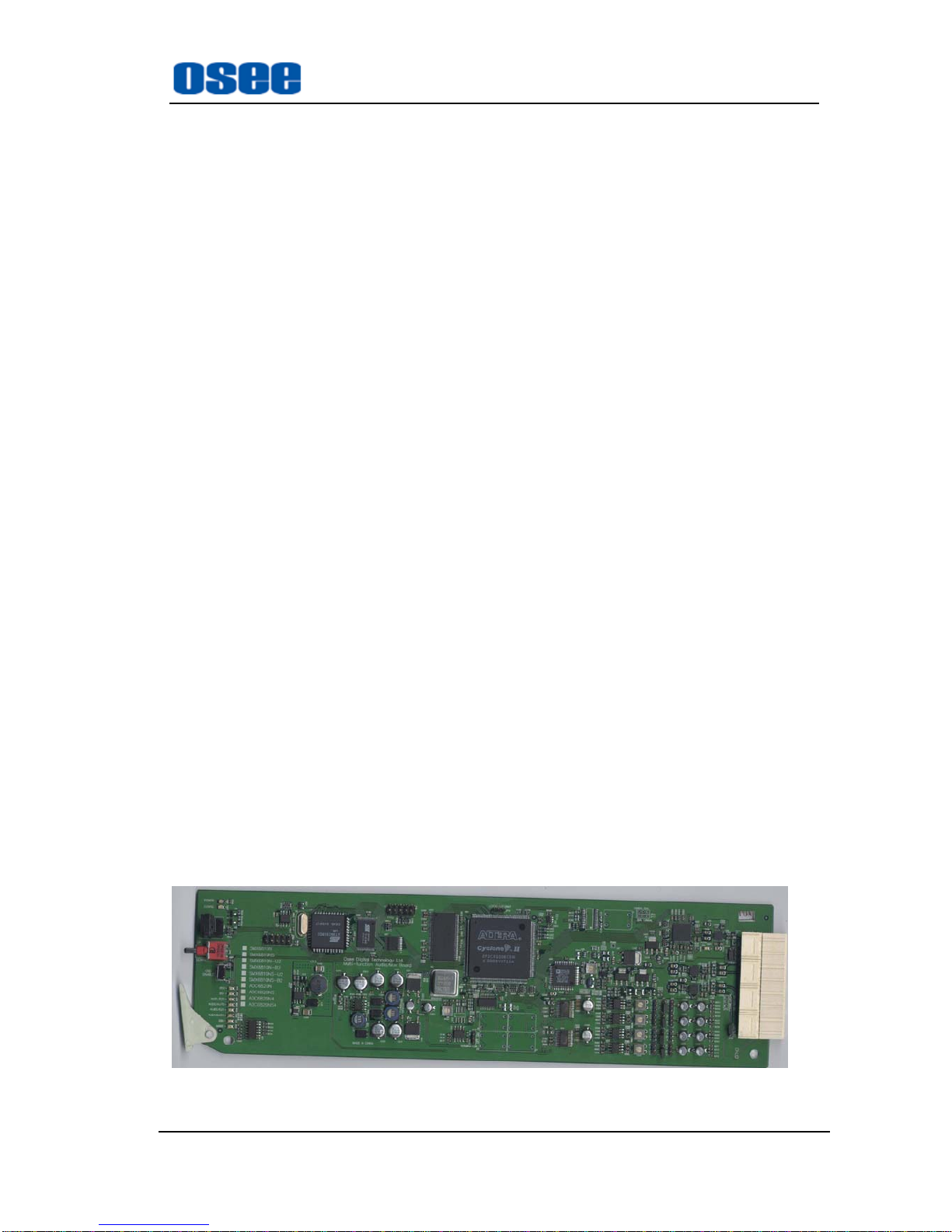
Module Descriptions .......................................................................................................................... 2
The Front Part of Module........................................................................................................... 2
Back Connector.................................................................................................................................. 3
ADC6820Nxx ............................................................................................................................ 3
Signal Flow ........................................................................................................................................ 4
Chapter 2 Installation.............................................................................................. 5
Overview............................................................................................................................................ 5
Maximum Power Ratings for Frame.................................................................................................. 5
Unpacking the Module....................................................................................................................... 5
Preparing the Product for Installation ........................................................................................ 5
Check the Packing List............................................................................................................... 6
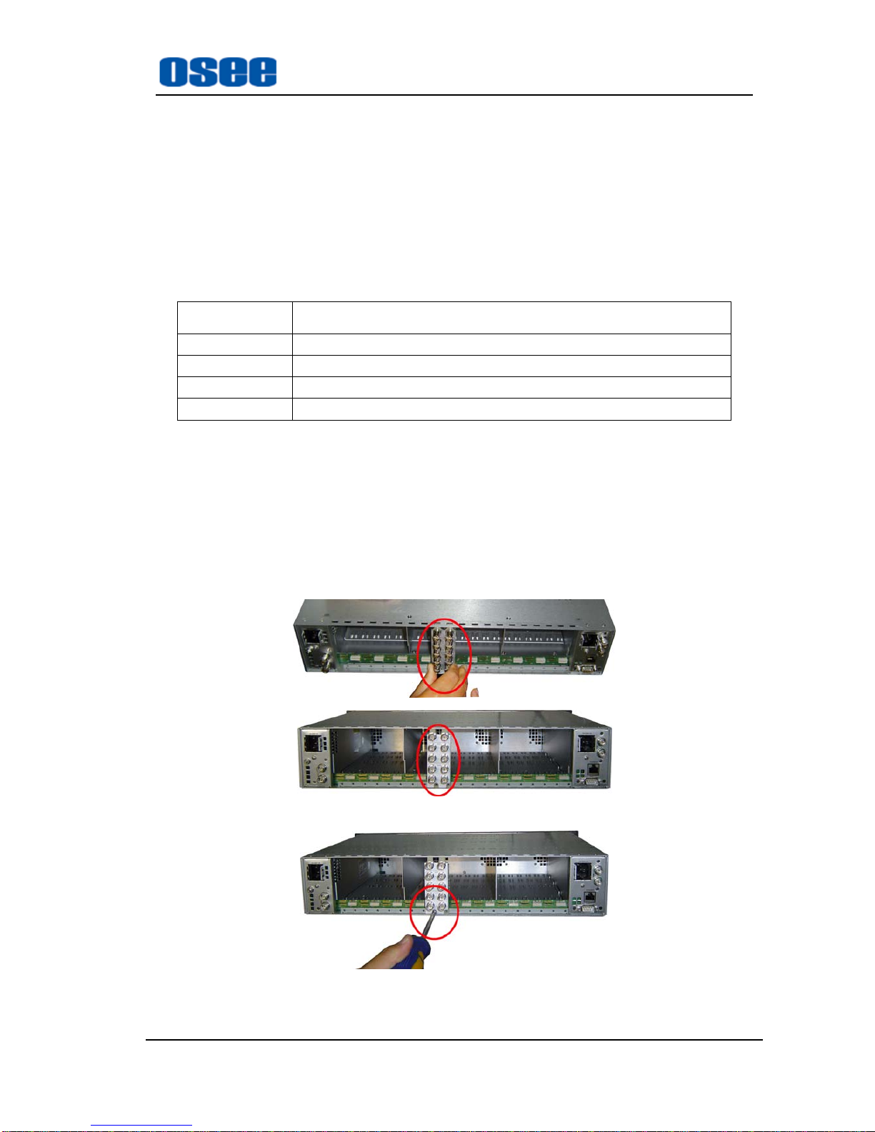
Installing the Module ......................................................................................................................... 6
Making the Connections .................................................................................................................... 7
Removing the Module........................................................................................................................ 7
Setting Jumper.................................................................................................................................... 8
LED Indicator .................................................................................................................................... 9
Output Select Mode ................................................................................................................... 9
General Mode............................................................................................................................. 9
Chapter 3 Operation and Control.......................................................................... 10
Switches and Keys ........................................................................................................................... 10
Chapter 4 Specifications....................................................................................... 16
Analog Audio input.......................................................................................................................... 16
Unbalanced AES/EBU Audio output ............................................................................................... 16
Balanced AES/EBU Output ............................................................................................................. 16
External Reference Input ................................................................................................................. 18
Warranty for osee product................................................................................... 19
What the warranty covers: ............................................................................................................... 19
What the warranty does not cover:................................................................................................... 19

DC6820NXX AUDIO A/D CONVERTER USER MANUAL
- 1 -
ADC6820Nxx Audio A/D Converter
Chapter 1 Introduction
Overview
Four modules will be introduced in Table 1-1 as follows.
Table 1-1 The Description of Audio Processing Module for A/D Converter
Module name Description
ADC6820N 2-chanel balanced analog audio inputs, 2-channel balanced and
unbalanced digital audio outputs respectively, the function of
audio delay
ADC6820N4 4-chanel balanced analog audio inputs, 2-channel balanced and
unbalanced digital audio outputs respectively, the function of
audio delay
ADC6820NS 2-chanel balanced analog audio inputs, 2-channel balanced and
unbalanced digital audio outputs respectively, the function of
audio delay and tracking.
ADC6820NS4 4-chanel balanced analog audio inputs, 2-channel balanced and
unbalanced digital audio outputs respectively, the function of
audio delay and tracking
Each module can provide 1-channel balanced or unbalanced DARS input, 1-channel Ref input, users can
select one of them as synchronization signal. Each module can generate fixed-rate tone signal and
provide flexibility in audio sampling and delay setting.
Features
The ADC6820Nxx offers the following features:
Convert analog audio input into balanced and unbalanced digital audio output
2/4 channel audio inputs, 2 channel balanced and unbalanced digital audio outputs respectively
Selectable delay and synchronizing mode
Either DARS or Ref can be selected as synchronized signal
flexibility in audio sampling, and can provide 16-bit, 20-bit, 24-bit sampling setting
Generating two fixed-frequency audio signals
-96 ~ +12dB audio gain range adjustment
flexibility in delay setting, and the maximum is 1980ms @ 32KHz manual delay

DC6820NXX AUDIO A/D CONVERTER USER MANUAL
- 2 -
Local or remote control and monitoring
Provide audio tracking function, only valid for ADC6820NS and ADC6820NS4
FCC Caution:
Any Changes or modifications not expressly approved by the party responsible for compliance could
void the user's authority to operate the equipment.
This device complies with part 15 of the FCC Rules.
Operation is subject to the following two conditions: (1) This device may not cause harmful interference,
and (2) this device must accept any interference received, including interference that may cause
undesired operation.
Note: This equipment has been tested and found to comply with the limits for a Class B digital device,
pursuant to part 15 of the FCC Rules. These limits are designed to provide reasonable protection against
harmful interference in a residential installation. This equipment generates uses and can radiate radio
frequency energy and, if not installed and used in accordance with the instructions, may cause harmful
interference to radio communications. However, there is no guarantee that interference will not occur in
a particular installation. If this equipment does cause harmful interference to radio or television
reception, which can be determined by turning the equipment off and on, the user is encouraged to try to
correct the interference by one or more of the following measures:
Reorient or relocate the receiving antenna.
Increase the separation between the equipment and receiver.
Connect the equipment into an outlet on a circuit different from that to which the receiver is connected.
Consult the dealer or an experienced radio/TV technician for help.
Module Descriptions
The Front Part of Module
Figure 1-1 shows the board of ADC6820Nxx
Fig. 1-1 the Board of ADC6820Nxx

DC6820NXX AUDIO A/D CONVERTER USER MANUAL
- 3 -
Back Connector
ADC6820Nxx
Fig.1-2 Back Connector of ADC6820Nxx
Tab. 1-2 description of ADC6820Nxx Back Connector
Item Description
AESO1, AESO2
(BNC connector)
AES/EBU unbalanced digital audio output
AESO1, AESO2
(3-pin audio connector)
AES/EBU balanced digital audio output
DATA IN audio tracking input, only valid for ADC6820NS and
ADC6820NS4
DARS/REF AES/EBU unbalanced digital audio synchronized input or
black burst synchronized input(see setting jumper for more
information)
DARS IN AES/EBU balanced digital audio synchronized input
ANALOG AUDIO IN
1A,1B
Analog audio input
ANALOG AUDIO IN
2A,2B
Analog audio input, only valid for ADC6820N4(S)

DC6820NXX AUDIO A/D CONVERTER USER MANUAL
- 4 -
Signal Flow
Fig. 1-3 Signal Flow of ADC6820N
Fig. 1-4 Signal Flow of ADC6820NS
Fig. 1-5 Signal Flow of ADC6820N4

DC6820NXX AUDIO A/D CONVERTER USER MANUAL
- 5 -
Fig. 1-6 Signal Flow of ADC6820NS4
Chapter 2 Installation
Overview
The power consumption for module and the maximum power ratings that frame can sustain have to be
confirmed before installing the module.
In this chapter, the following topics on installation process for ADC6820Nxx are discussed below:
Unpacking the module
Setting Jumper
Installing the module
Making the connections
Removing the module
Maximum Power Ratings for Frame
The maximum power ratings that different types of frames can sustain are listed in the Table 2-1
Tab. 2-1 Maximum Power Consumption
Frame Maximum Voltage Redundant Power Supplies Numbers of Slots
6800N-1U 40W Yes 4
6800N-2U 60W Yes 10
Unpacking the Module
Preparing the Product for Installation
Contact your dealer right now if any items are missing.

DC6820NXX AUDIO A/D CONVERTER USER MANUAL
- 6 -
Follow the procedures below before installing the module:
Check the equipment for any invisible damage that may have occurred during transit.
Confirm all the items listed on the packing list have been received.
Remove all the packing material including electrostatic-resistant packing.
Retain these packing for future use.
Check the Packing List
Tab. 2-2 Packed Components
Model Name Description
ADC6820N ADC6820N module (1pc); back connector (1pc), and other accessories
ADC6820NS ADC6820NS module (1pc); back connector (1pc), and other accessories
ADC6820N4 ADC6820N4 module (1pc); back connector (1pc), and other accessories
ADC6820NS4 ADC6820NS4 module (1pc); back connector (1pc), and other accessories
Installing the Module
Caution:Static electricity may cause sensitive semiconductor out of order. Avoid installing
or removing the module in the electrostatic-induced environment.
Follow the following steps to install the module:
Step 1
Step2
Step3

DC6820NXX AUDIO A/D CONVERTER USER MANUAL
- 7 -
Step 4
Step5
Fig. 2-1 Installation of 2U Frame of 6800N Series
Locate the position for back connector and insert the back connector
Fasten the screw to fix the back connector.
Locate the slot for module.
Get the module installed in the slot, push the module slightly along the slot, press module again to
confirm that the module is installed firmly and then close swivel handle.
Install the front panel.
Making the Connections
Please connect signals based on Fig. 1-2.
Removing the Module
Follow the following steps to remove ADC6820Nxx module:
1. Open the front part of frame.
2. Open the swivel handle to the full.
3. First make sure the frame stands firmly, and then pull the module gently along the slot till out
of frame.
4. Install the front panel.

DC6820NXX AUDIO A/D CONVERTER USER MANUAL
- 8 -
Setting Jumper
There exist four 3-pin jumpers, and the following table gives their definition.
Tab. 2-3 Description of ADC6820Nxx Jumpers
Item Description
JP15
LOCAL/FRAME.
LOCAL: a external synchronized signal input
FRAME: The synchronized signal is provided by 6800 Frame
the default setting is local
JP17(TERMINATION)
ON/OFF
Only valid for DATA IN(refer
to Tab. 1-2)
When setting JP17 at ON, you need to connect BNC with 75Ω
termination.
When setting JP17 at OFF, you need not to connect BNC with
75Ωtermination.
the default setting is on.
JP19
REF/COMP
REF: synchronized signal input
COMP: reserved
you must set JP19 at REF (Please don’t change the default
setting).
JP20
DARS/BB
DARS: AES/EBU digital audio synchronized signal input
BB: analog black burst synchronized signal input
JP13,JP14
BAL/UNBAL
BAL: AES/EBU balanced digital audio synchronized input
UNBAL: AES/EBU unbalanced digital audio synchronized
input
JP16
DATA/ SDI
DATA: audio tracking signal input
SDI: reserved
you must set JP16 at DATA (Please don’t change the default
setting).
JP18
(LOC/RMT)/LOCAL
LOCAL: local control
LOC/RMT: local and remote control
used to choose control mode, the default setting is LOC/RMT.
JP1, JP2, JP3, JP4, JP5, JP6,
JP7, JP8, JP9, JP10, JP11, JP12
Select the gain of audio outputs
16dB~28dB adjustable.
When jumpers JP1~JP12 is unconnected, the gain is 16dB.
Tab. 2-4 gives an example for jumper-setting:
Tab. 2-4 Setting a Synchronized Signal Input via Jumpers
Item Description
Choose a common synchronized
signal provided by 6800N Frame
Set JP15 at FRAME
Choose a synchronized signal
provided by back connector
Set JP15 at LOCAL, JP19 at REF, and JP20 at BB

DC6820NXX AUDIO A/D CONVERTER USER MANUAL
- 9 -
Choose a DARS unbalanced digital
audio input as synchronization
Set JP19 at REF, JP20 at DARS, JP13 and JP14 at
UNBAL
Choose a DARS unbalanced digital
audio input as synchronization
Set JP19 at REF, JP20 at DARS, JP13 and JP14 at BAL
LED Indicator
There exist two LED modes, one is output select mode, the other is general mode. LED mode is related
with the positions of SW1.
Output Select Mode
To ADC6820N(S), the position of SW1 is at 5 or 6.
But to ADC6820N(S)4, the position of SW1 is at A, B, C or D while being in the status of Bank 0.
Tab. 2-5 Description of LED Indicator (output select mode)
Item (color)Related indicator Description
POWER(green)Power supply On: Power is supplied.
CONFIG(orange)Device status On: The device is Initializing.
BS0(orange)
Bank select
(only for
ADC6820N(S)4 )
On, Bank 1 is selected
Off, Bank 0 is selected
BS1 Reserved
AUD1/525
(green)IN 1A On, choose IN 1A signal as output
Off, not choose IN 1A signal as output
AUD2/AUTO
(green)IN 1B On, choose IN 1B signal as output
Off, not choose IN 1B signal as output
AUD3/625
(green)
IN 2A (only for
ADC6820N(S)4)
On, choose IN 2A signal as output
Off, not choose IN 2A signal as output
AUD4/DARS
(green)
IN 2B(only for
ADC6820N(S)4)
On, choose IN 2B signal as output
Off, not choose IN 2B signal as output
EBO(green)MIX
On, choose MIX signal as output
Off, not choose MIX signal as output
MODE(green)Tone
On, choose tone signal as output
Off, not choose tone signal as output
Note: when choosing in 1 sum or in 2 sum as output, LED MIX and related LED will be on. For
example, when in 1 sum is selected as output, LED 1A, 1B and MIX are all on.
General Mode
To ADC6820N(S), the position of SW1 is setting at other point except 5 and 6.
But to ADC6820N(S)4, the position of SW1 is setting at other point except A, B, C and D while
being in Bank 0. SW1 can be setting at any point during Bank 1.

DC6820NXX AUDIO A/D CONVERTER USER MANUAL
- 10 -
Tab. 2-6 Description of LED Indicator (general mode)
Item (color)Related indicator Description
POWER(green)Power supply On: Power is supplied.
CONFIG(orange)Device status On: The device is Initializing.
BS0(orange)
Bank select
(only for
ADC6820N(S)4 )
On: Bank 1 is selected
Off: Bank 0 is selected
BS1 Reserved
AUD1/525
(green)IN 1A
On: Analog audio input is right
Off: No signal
Flashing: There exist audio signal but the signal is in
overload error
AUD2/AUTO
(green)IN 1B
On: Analog audio input is right
Off: No signal
Flashing: There exist audio signal but the signal is in
overload error
AUD3/625
(green)
IN 2A (only for
ADC6820N(S)4)
On: Analog audio input is right
Off: No signal
Flashing: There exist audio signal but the signal is in
overload error
AUD4/DARS
(green)
IN 2B(only for
ADC6820N(S)4)
On: Analog audio input is right
Off: No signal
Flashing: There exist audio signal but the signal is in
overload error
EBO(green)Ref
On: the current setting is locked at genlock and work
in normal
Off: the current setting is not locked at genlock
Flashing: the current setting is locked at genlock but
the genlock signal is not available
MODE(green)DARS
On: the current setting is locked at DARS and work
in normal
Off: the current setting is not locked at DARS
Flashing: the current setting is locked at DARS but
the DARS signal is wrong or not available
Chapter 3 Operation and Control
Switches and Keys
Refer to Figure 3-1 or Table 3-1(Bank 0)or Table 3-2(Bank 1)to complete control

DC6820NXX AUDIO A/D CONVERTER USER MANUAL
- 11 -
Fig. 3-1 Switches and key
Rotate SW1 at the position of 0, and select the proper Bank by SW2.
Bank Selection
The SW1 has two Banks
Rotate the SW1 at the position of “0”. The position of “0” is always used to select Bank.
Turn SW2 up or down to select Bank.
1. SW1 Mode Selection
SW1 is a 16-position rotary switch, which is used to select the specific setting.
The selection range is: 0, 1, 2, 3, 4, 5, 6, 7, 8, 9, A, B, C, D, E, F.
2. SW2 Mode Selection
SW2 is a toggle switch, which is used to decide the concrete figure of the setting made by SW1.
SW2 is a 3-position toggle switch, used to decide the concrete figure of the setting made by SW1.
To keep SW2 at the position of “UP” or “DOWN”, the continuous adjustment can be achieved.
3. SW3
Press the SW3 to activate OSD.
SW1
SW2
SW3

DC6820NXX AUDIO A/D CONVERTER USER MANUAL
- 12 -
Tab. 3-1 ADC6820N(S)Function setting
SW1
Position Parameter Function Options Default
0 Reserved Reserved
1 In Ch 1A
Level
Adjust the gain of
Channel-1A
-96~ +12dB
in 0.5dB step 0dB
2 In Ch 1B
Level
Adjust the gain of
Channel 1B
-96~ +12dB
in 0.5dB step 0dB
3 In Ch 1A
Invert Invert Channel-1A Off
On Off
4 In Ch 1B
Invert Invert Channel-1B Off
On Off
5 Out Ch 1A
Source
select one source as
the output of
Channel-1A
in 1A/in 1B/in 1 sum
/tone1/tone2/mute in 1A
6 Out Ch 1B
Source
select one source as
the output of
Channel-1B
in 1A/in 1B/in 1 sum
/tone1/tone2/mute in 1B
7 Out bits
Setting the word
length of audio output 16/20/24 24
8 Lock Source
Select one signal that
audio signal is locked
to
DARS/genlock/freerun DARS
9 Sample Rate
Setting sampling rate
(note: when audio
signal is locked to
DARS, that is, lock
source=DARS, the
setting is invalid.)
32k/48k/96k 48k
A Ch1A Delay Channel 1A delay
0~1980 ms @ 32 kHz
0~1320ms @ 48 kHz
0~660 ms @ 96 kHz
0.000ms
B Ch1B Delay Channel 1B delay
0~1980 ms @ 32 kHz
0~1320ms @ 48 kHz
0~660 ms @ 96 kHz
0.000ms

DC6820NXX AUDIO A/D CONVERTER USER MANUAL
- 13 -
SW1
Position Parameter Function Options Default
C Auto Track
Audio tracking delay
(only valid for
ADC6820NS)
Enable
Disable Disable
D No Signal
Delay No Signal Delay 0 ~255s 30s
E No Signal
Threshold No Signal Threshold -72dB/-66dB/-60dB/-54dB/-48dB -60dB
F Factory recall
Restore the default of
parameters Yes (toggle SW2 to restore)No
Tab. 3-2 ADC6820N(S)4 Function setting (Bank 0)
SW1
Position Parameter Function Options Default
0 Bank select Select Bank Bank 0
Bank 1 Bank 0
1 Lock Source
Select one signal
that audio signal is
locked to
DARS/Genlock/freerun/ DARS
2 In Ch 1A Level Adjust the gain of
Channel-1A
-96~ +12dB
in 0.5dB step 0dB
3 In Ch 1B Level Adjust the gain of
Channel 1B
-96~ +12dB
in 0.5dB step 0dB
4 In Ch 2A Level Adjust the gain of
Channel-2A
-96~ +12dB
in 0.5dB step 0dB
5 In Ch 2B Level Adjust the gain of
Channel 2B
-96~ +12dB
in 0.5dB step 0dB
6 In Ch 1A Invert Invert Channel-1A Off
On Off
7 In Ch 1B Invert Invert Channel-1B Off
On Off

DC6820NXX AUDIO A/D CONVERTER USER MANUAL
- 14 -
SW1
Position Parameter Function Options Default
8 In Ch 2A Invert Invert Channel-2A Off
On Off
9 In Ch 2B Invert Invert Channel-2B Off
On Off
A Out Ch 1A
Source
select one source as
the output of
Channel-1A
in 1A/in 1B /in 2A
/in 2B /in 1 sum
/ in 2 sum /tone1/tone2/mute
in 1A
B Out Ch 1B
Source
select one source as
the output of
Channel-1B
in 1A/in 1B /in 2A
/in 2B /in 1 sum
/ in 2 sum /tone1/tone2/mute
in 1B
C Out Ch 2A
Source
select one source as
the output of
Channel-2A
in 1A/in 1B /in 2A
/in 2B /in 1 sum
/ in 2 sum /tone1/tone2/mute
in 2A
D Out Ch 2B
Source
select one source as
the output of
Channel-2B
in 1A/in 1B /in 2A
/in 2B /in 1 sum
/ in 2 sum /tone1/tone2/mute
in 2B
E Reserved
F Factory recall
Restore the default
of parameters Yes (toggle SW2 to restore)No
Tab. 3-3 ADC6820N(S)4 Function setting (Bank 1)
SW1
Position Parameter Function Options Default
0 Bank select Select Bank Bank 0
Bank 1 Bank 0
1 Out Ch1 bits
Setting the word
length of audio output
Channel 1
16/20/24 24
2 Out Ch2 bits
Setting the word
length of audio output
Channel 2
16/20/24 24
3 Sample Rate
Setting sampling rate
(note: when audio
signal is locked to
DARS, that is, lock
32k/48k/96k 48k

DC6820NXX AUDIO A/D CONVERTER USER MANUAL
- 15 -
SW1
Position Parameter Function Options Default
source=DARS, the
setting is invalid.)
4 Ch1A Delay Ch1A Delay
0~1980 ms @ 32 kHz
0~1320ms @ 48 kHz
0~660 ms @ 96 kHz
0.000ms
5 Ch1B Delay Ch1B Delay
0~1980 ms @ 32 kHz
0~1320ms @ 48 kHz
0~660 ms @ 96 kHz
0.000ms
6 Ch2A Delay Ch2A Delay
0~1980 ms @ 32 kHz
0~1320ms @ 48 kHz
0~660 ms @ 96 kHz
0.000ms
7 Ch2B Delay Ch2B Delay
0~1980 ms @ 32 kHz
0~1320ms @ 48 kHz
0~660 ms @ 96 kHz
0.000ms
8 Auto Track
Audio tracking delay
(only valid for
ADC6820NS4)
Enable
Disable Disable
9 No Signal
Delay No Signal Delay 0 ~255s 30s
A No Signal
Threshold No Signal Threshold -72dB/-66dB/-60dB/-54dB/-48dB -60dB
B~F Reserved
Note the following when setting parameters
When power is supplied, the default setting of ADC6820N(S)4 is Bank 0.
It is not need to choose Bank to ADC6820N(S), rotate SW1 to set at one position, and then toggle
SW2 to adjust the corresponding parameter.
Keep SW2 up or down can adjust continually
Go back to the default
To ADC6820N(S)4, set it at Bank 0, rotate SW1 to F, and toggle SW2.
To ADC6820N(S), rotate SW1 to F, and toggle SW2.
When setting ADC6820N(S)4, please pay attention to the status of LED indicators.
Adjust delay

DC6820NXX AUDIO A/D CONVERTER USER MANUAL
- 16 -
There are 1320 steps the range between 0 and the maximum. Each step means different. One step
denotes 1.5ms when the sampling rate is 32KHz, 1.0ms when the sampling rate is 48KHz, and
0.5ms when the sampling rate is 96KHz.
Chapter 4 Specifications
In this chapter, the specifications in the following subjects are introduced:
Analog Audio input
Unbalanced AES/EBU Output
Balanced AES/EBU Output
External Reference Input
Analog Audio input
Tab. 4-1 Analog Audio Input Specifications
Item Parameter
Standard Electronic, balanced
connector 3-pin audio connector
Input coupling AC
Impedance High resistance
Level range +16 dBu to +28 dBu
Unbalanced AES/EBU Audio output
Tab.4-2 Unbalanced AES/EBU Output Specifications
Item Parameter
Connector BNC per IEC 169-8
Level 1.0 V +/-10% (peak to peak)
DC offset 0.0V±50.0mV
Rise/fall time 30 to 44 ns (10% to 90% amplitude)
Impedance 75 Ω
Return loss >25 dB, 0.1 to 6.0 MHz
Balanced AES/EBU Output
Tab. 4-3 Balanced AES/EBU Output Specifications
Item Parameter
Connector 3-pin connector (male)
Signal level 2.0 to 7.0 V (peak to peak)
This manual suits for next models
3
Table of contents
Other OSEE Media Converter manuals