OSEE DEC6800N User manual

DEC/DES6800 CVBS/SDI Converter
USER MANUAL

Product Information
Model: DEC/DES6800 CVBS/SDI Converter
Version: V010000
Release Date: March 28th, 2008
Company
OSEE TECHNOLOGY CO., LTD.
Contact Information
Address: No.22 Building, No.68 zone, Beiqing Road, Haidian District,
Beijing, China
Post Code: 100094
Tel: (+86) 010-62434168
Fax: (+86) 010-62434169
Web: http://www.osee-dig.com/
E-mail: [email protected]

Contents
Chapter 1 Introduction.......................................................................................... 1
Overview............................................................................................................................................ 1
General Description of Modules ........................................................................................................ 1
Features.............................................................................................................................................. 1
Introduction to Module ...................................................................................................................... 2
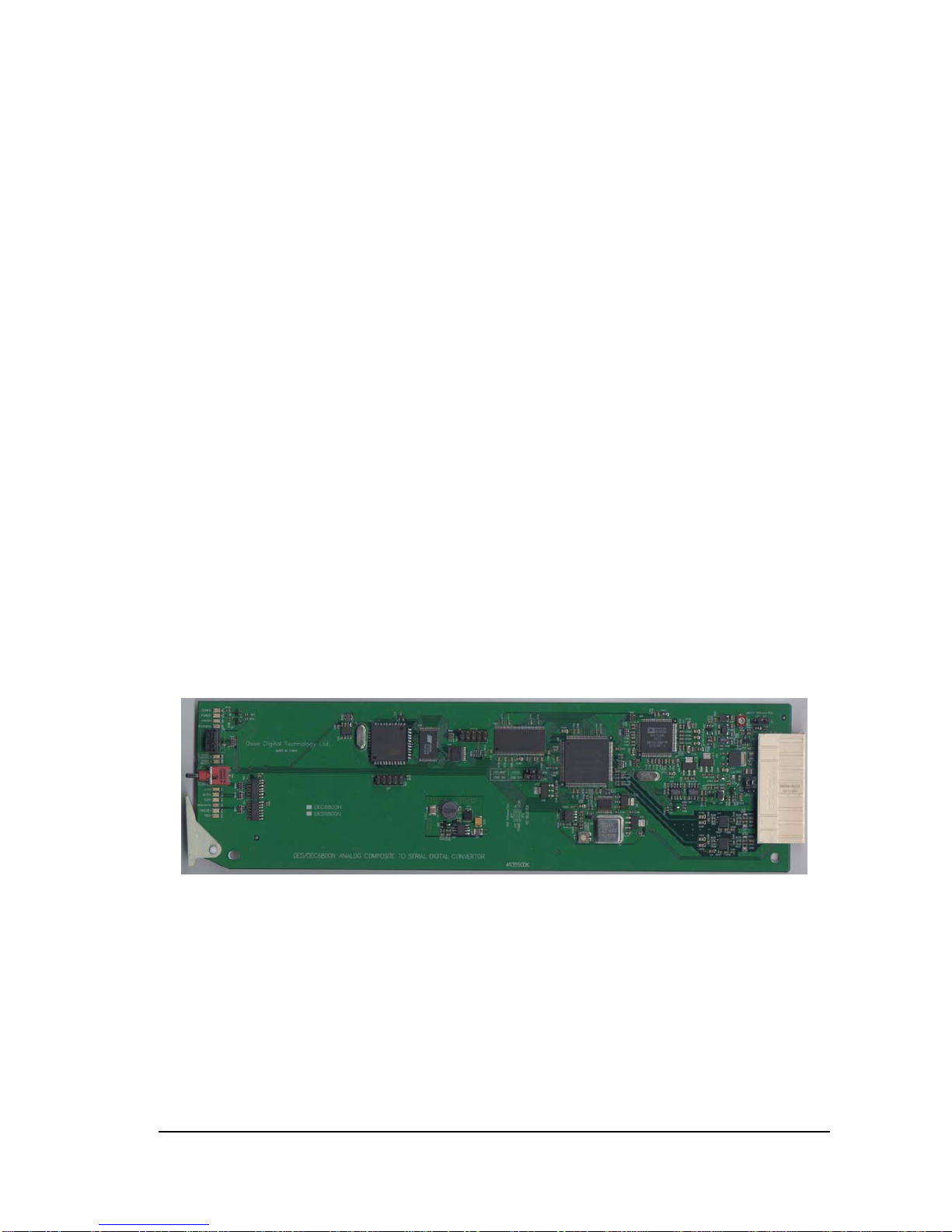
The Front Part of Module........................................................................................................... 2
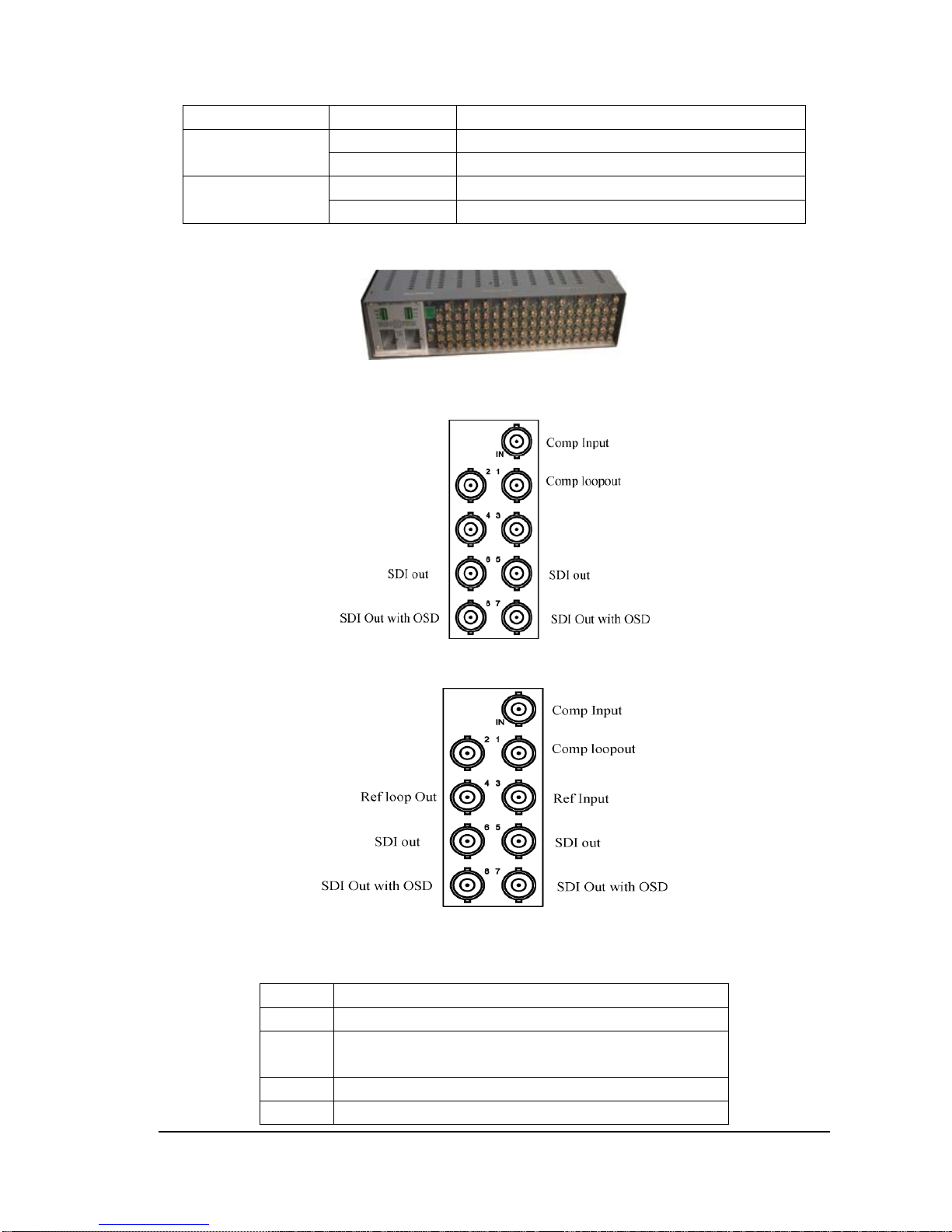
Back Connector.......................................................................................................................... 4
Back Connector for DEC/DES6800N........................................................................................ 4
Signal Flow Chart .............................................................................................................................. 5
Chapter 2 Installation ........................................................................................... 5
Overview............................................................................................................................................ 5
Maximum Power Dissipation for Frame............................................................................................ 6
Unpacking the Module....................................................................................................................... 6
Preparation for Installation......................................................................................................... 6
Check Packing List .................................................................................................................... 6
Module Installation ............................................................................................................................ 6
Signal Connections .................................................................................................................... 7
Module Removal........................................................................................................................ 7
Chapter 3 Operation and Control ......................................................................... 8
User Control and Operating Instruction............................................................................................. 8
Pay attention to the followings when configuration......................................................................... 14
Composite in Video Path Processing: ...................................................................................... 14
Decoded Video Path Processing:.............................................................................................. 15
Video Timing and Freeze Controls .......................................................................................... 15
Freeze Mode............................................................................................................................. 15
OSD Mode ............................................................................................................................... 15
Set the Jumper.................................................................................................................................. 15
Chapter 4 Specifications..................................................................................... 16
Analog Video Input .......................................................................................................................... 16
SDI Video Processing ...................................................................................................................... 16
SDI Video Output............................................................................................................................. 16
Phase ................................................................................................................................................ 16
Chapter 5 Warranty for osee product................................................................ 17
What the warranty covers: ............................................................................................................... 17
What the warranty does not cover:................................................................................................... 17

DEC/DES6800 CVBS/SDI Converter - 1 -
DEC/DES6800 CVBS/SDI Converter
Chapter 1 Introduction
Overview
In this chapter the following modules are introduced:
DEC6800N:Supporting one composite loop output, two SDI output and two SDI outputs with OSD.
DES6800N:Supporting one composite loop output, one REF loop input, one REF loop output, two SDI
output and two SDI outputs with OSD.
The above modules can be installed in the 6800N Series frame.
General Description of Modules
The DEC/DES6800N is a compact 12-bit decoder and can convert NTSC, PAL and composite signal
into 4:2:2 SDI component signal with broadcasting quality.
The module can handle the signal like the satellite feed and microwave which contains a plenty of noise.
The DES6800 has a built-in synchronizer.
The DEC/DES6800N is controlled by switch on the front panel. The table1-1 gives a general description
of modules.
Table 1-1 DEC/DES6800N
Module Description
DEC6800N Has one composite loop output, two SDI outputs, and two SDI
outputs with OSD
DES6800N Has one composite loop output, one REF loop input, one REF loop
output, two SDI outputs and two SDI outputs with OSD.
Features
The DEC/DES6800 has the following features:
4 oversampling 12-bit A/D converter
Auto-detection on NTSC/PAL for input
AGC/ACC
Full functional processing amplifier
Progressive VBI processing
Built-in test pattern generator (color bar and black burst)
EDH insertion
OSD can be overlaid to the output
NTSC/PAL reference input
Built-in synchronizer

DEC/DES6800 CVBS/SDI Converter - 2 -
FCC Caution:
Any Changes or modifications not expressly approved by the party responsible for compliance could
void the user's authority to operate the equipment.
This device complies with part 15 of the FCC Rules.
Operation is subject to the following two conditions: (1) This device may not cause harmful interference,
and (2) this device must accept any interference received, including interference that may cause
undesired operation.
Note: This equipment has been tested and found to comply with the limits for a Class B digital device,
pursuant to part 15 of the FCC Rules. These limits are designed to provide reasonable protection against
harmful interference in a residential installation. This equipment generates uses and can radiate radio
frequency energy and, if not installed and used in accordance with the instructions, may cause harmful
interference to radio communications. However, there is no guarantee that interference will not occur in
a particular installation. If this equipment does cause harmful interference to radio or television
reception, which can be determined by turning the equipment off and on, the user is encouraged to try to
correct the interference by one or more of the following measures:
Reorient or relocate the receiving antenna.
Increase the separation between the equipment and receiver.
Connect the equipment into an outlet on a circuit different from that to which the receiver is connected.
Consult the dealer or an experienced radio/TV technician for help.
Introduction to Module
The Front Part of Module
Figure 1-1 DEC/DES6800N
Note: Table 1-1 Introduction to the switch and status LED indicator. Refer to Chapter Three for detailed
instructions on switch and status LED indicator.

DEC/DES6800 CVBS/SDI Converter - 3 -
Figure 1-2 Switch and Status LED Indicator on the Front Part of DEC/DES6800
Table 1-2:Status Indicator and Its Function
LED Indication Condition
CONFIG
(yellow)
Off Module is in normal operating mode.
On Module is initializing or initialized error.
POWER
(green)
Off No power to module
On Normal operation, module is powered.
ERROR
(red)
Off Normal operation.
On continuously No signal present on input.
Flashing No reference or input signal line rate does not match
the reference.
WARNING(red) Off when module runs in disorder
BANK MARK
(yellow)
Bank 0
Off On/Off combination indicates which bank is selected
(described in Table 3)
On
BANK MARK1
(yellow) Bank1
Off
On
625(green)
On continuously Valid 625 video input is present.
Off Standard 625 is not selected or under auto-detection,
no valid 625 standard is detected.
Flashing
Standard 625 is detected and no valid 625 video input
is present.
AUTO(green)
On Auto standard is selected
Off Auto standard is not selected
525(green)
On continuously Valid 525 video input is present.
Off Standard 525 is not selected or under auto-detection,
no valid 525 standard is detected.
Flashing
Standard 525 is selected and no valid 525 video input
is present.
GENLOCK(yellow)
Off Reference genlock mode is not selected
On Reference genlock mode is selected

DEC/DES6800 CVBS/SDI Converter - 4 -
LED Indication Condition
FREEZE (green)
Off Freeze is disabled
On Freeze is enabled
TSG(yellow)
Off TSG output is disabled
On TSG output is enabled
Back Connector
Figure 1-3 6800N-U2 frame Back Connector
Back Connector for DEC/DES6800N
Figure 1-4 Back Connector for DEC6800N
Figure 1-5: Back Connector for DES6800N
Table 1-3 Back Connector for DEC6800N
Location Description
IN Composite loop input
1 Composite loop output(the JP1 of DEC/DES6800N has to be
set on the location “off” when it is in loop through). )
2 SDI output
3 SDI output

DEC/DES6800 CVBS/SDI Converter - 5 -
Location Description
4 SDI output with OSD
5 SDI output with OSD
Table 1-4 Back Connector for DES6800N
Location Description
IN Composite loop input
1 Composite loop output (the JP1 of DEC/DES6800N has to
be set on the location “off” when it is in loop through). )
2 Audio tracking data output: not function
3 REF loop input
4 REF loop output
5 SDI output
6 SDI output
7 SDI output with OSD
8 SDI output with OSD
Signal Flow Chart
Figure 1-6 Signal Flow for DEC/DES6800N
Chapter 2 Installation
Overview
The power dissipation of module and the maximum power dissipation that frame can sustain have to be
confirmed before module’s installation.
The following topics on installation process of DEC/DES6800N will be introduced in this chapter
below:
Unpacking Module
Setting Jumper
Module Installation

DEC/DES6800 CVBS/SDI Converter - 6 -
Signal Connection
Module Removal
Maximum Power Dissipation for Frame
The maximum voltage that 6800N series frame can sustain.
Table 2-1 Maximum voltage that 6800N Series frame that can sustain
Frame Maximum Voltage Redundant Power Supplies Numbers of Slots
6800N-1U 40W Yes 4
6800N-2U 60W Yes 10
Unpacking the Module
Preparation for Installation
Contact your dealer right away once any item is missing.
Follow the following steps before module’s installation:
Check the equipment if any visible damage found during the transit.
Confirm that your have received all the items listed on the packing list.
Remove all the packing material as well as electrostatic-resistant packing if available for the
equipment
Keep these packing for future use.
Check Packing List Table 2-2 Packed Components
Model Description
DEC6800N DEC6800 module (1pc); back connector (1pc), and other accessories
DES6800N DES6800 module (1pc); back connector (1pc), and other accessories
Module Installation
Caution:Static electricity may cause sensitive semiconductor out of order. Avoid installing
or removing the module in the electrostatic-induced environment.
Follow the next steps to install the module:
Step 1

DEC/DES6800 CVBS/SDI Converter - 7 -
Step2
Step3
Step 4
Step5
Fig. 2-1 Installation of 2U Frame of 6800N Series
Locate the position for back connector and insert the back connector
Fasten the screw to fix the back connector.
Locate the slot for module.
Get the module installed in the slot, push the module slightly along the slot, press module again to
confirm that the module is installed firmly and then close swivel handle.
Install the front panel.
Signal Connections
All signal connections shall be made through the general bus of 6800N Series frame
Module Removal
Follow the following steps to remove VDA6800N module:
1. Open the front panel
2. Open the swivel handle to the full.

DEC/DES6800 CVBS/SDI Converter - 8 -
3. First make sure that the frame stands firmly, and then pull gently the module along the slot out
of frame.
4. Install the front panel.
Chapter 3 Operation and Control
In the chapter 3, the following topics on DES6800N are introduced:
User’s Control
Setting the Parameters
Setting the Jumper
User Control and Operating Instruction
Refer the Table for BANK to fulfill the function.
Figure 3-1 SW1 SW2 Location
Select the SW1 at the location“0”, and SW2 is used to select the BANK.
BANK Selection
SW1 has four BANK.
Set SW1 to the location 0, and location “0” is always used to select BANK.
Switch SW2 up or down to select BANK A.
Table3-1 BANK Select
BANK 0 BANK 1 BAN
K
selected
Off Off 0
Off On 1
On Off 2
On On 3
The function of SW1 is set as default, refer to Table 3-1 for defaults:
1. SW1 Mode Selection
The switch of SW1 is a 16-position rotary switch and it is used to select the specific function.
The range for selection is: 0, 1, 2, 3. 4, 5, 6, 7, 8, 9, A, B, C, D, E, F.
2. SW2 Mode Selection
The Toggle Switch of SW2
The SW2 is a toggle switch that has 3 positions with auto returning back the middle position. And it is

DEC/DES6800 CVBS/SDI Converter - 9 -
used to adjust the function that is set by SW1.
Set the SW2 at the position of UP or DOWN to allow the continuous adjustment.
All the parameters that can be configured on the DEC/DES6800N are as follows:
Table3-2 Functional Parameters of Bank 0
SW1
Position Function
Description OSD Text Default
0 Select bank 0:0 Bank Selection Bank 0
1 Turn OSD on or off
0:1 Video: Status
(Loss/625/525)
Ref: Status
(Loss/Ref525/Ref625/Input)
OSD
Disable
2 Select video standard 0:2 Vid Standard
Auto/625/525 Auto
3 Analog video input gain
0:3 In Vid Gain
80.96%~200% for 625
84.93%~200% for 525
100%
4 Chroma gain
0:4 In Chm Gain
50%~200% 100%
5 Turn AGC on or off 0:5 AGC
On/Off On
6 Turn ACC on or off 0:6 ACC
On/Off On
7 Adjust luma gain 0:7 Luma Gain
50%~200% 100%
8 Adjust black level 0:8 Black Level
7.9~-7.9IRE 0 IRE
9 Adjust chroma gain 0:9 Chroma Gain
50%~200% 100%
A Adjust hue
0:A Hue
90~-90 (only for NTSC) 0
B Select decoding mode 0:B Decode Mode
Comb/Notch Comb
C 0:C Reserve
D Enable or disable black
clip
0:D Black Clip
Enable/Disable Disable
E 0:E Reserve
F 0:F Recall Def
Table3-3 Functional Parameters of Bank 1 (525 line rate)
SW1
Position Function
Description OSD
Text Default
0 Select bank 1:0 Bank Selection Bank 0

DEC/DES6800 CVBS/SDI Converter - 10 -
SW1
Position Function
Description OSD
Text Default
1 Selects the genlock
Mode
1:1 Genlcok Mode
Free Run/Ref/Input
(only for DES6800)
Ref
2 Adjust horizontal timing
1:2 H Phase
0~1715
(only for DES6800)
0
3 Adjust vertical timing
1:3 V Phase
0~524
(only for DES6800)
0
4 Turn freeze on or off
1:4 Freeze
On/Off
(only for DES6800)
Off
5 Select type of freeze
1:5 Freeze Mode
Field 1/Field 2/Frame
(only for DES6800)
Field 1
6 Enable or disable hot
switch
1:6 Hot Switch
Enable/Disable
(only for DES6800)
Enable
7 Select loss of video mode 1:7 LossVid Mode
Disp Test/Pass/Hot Switch
Hot
Switch
8 Turn TSG on or off 1:8 TSG
On/Off Off
9 Select color bar or black
field
1:9 TSG Sel
Color Bar/Black Black
A 1:A Reserve
B 1:B Reserve
C 1:C Reserve
D 1:D Reserve
E 1:E Reserve
F 1:F Reserve
Table3-4 Functional Parameters of Bank 1 (625 line rate)
SW1
Position Function
Description OSD Text Default
0 Select bank 1:0 Bank Selection Bank 0
1 Selects the genlock
Mode
1:1 Genlcok Mode
Free Run/Ref/Input Ref
2 Adjust horizontal timing
1:2 H Phase
0~1727
0
3 Adjust vertical timing 1:3 V Phase
0~624 0

DEC/DES6800 CVBS/SDI Converter - 11 -
SW1
Position Function
Description OSD Text Default
4 Turn freeze on or off 1:4 Freeze
On/Off Off
5 Select type of freeze 1:5 Freeze Mode
Field 1/Field 2/Frame
Field 1
6 Enable or disable hot
switch
1:6 Hot Switch
Enable/Disable
Enable
7 Select loss of video mode 1:7 LossVid Mode
Disp Test/Pass/Hot Switch
Hot
Switch
8 Turn TSG on or off 1:8 TSG
On/Off Off
9 Select color bar or black
field
1:9 TSG Sel
Color Bar/Black Black
A 1:A Reserve
B 1:B Reserve
C 1:C Reserve
D 1:D Reserve
E Pass or blank VBI
1:E Line6 VBI
Blank/Pass
F Pass or blank VBI
1:E Line7 VBI
Blank/Pass
Table3-5 Functional Parameters of Bank 2 (525 line rate)
SW1
Position Function
Description OSD Text Default
0 Select bank 2:0 Bank Selection Bank 0
1 2:1 Reserve
2 2:2 Reserve
3 Pass or blank VBI 2:3 Line10 VBI
Blank/Pass Pass
4 Pass or blank VBI 2:4 Line11 VBI
Blank/Pass Pass
5 Pass or blank 2:5 Line12 VBI
Blank/Pass Pass
6 Pass or blank
2:6 Line13 VBI
Blank/Pass
Line 13 VBI
Pass
7 Pass or blank VBI 2:7 Line14 VBI
Blank/Pass Pass
8 Pass or blank VBI 2:8 Line15 VBI
Blank/Pass Pass

DEC/DES6800 CVBS/SDI Converter - 12 -
SW1
Position Function
Description OSD Text Default
9 Pass or blank VBI 2:9 Line16 VBI
Blank/Pass Pass
A Pass or blank VBI 2:A Line17 VBI
Blank/Pass Pass
B Pass or blank VBI 2:B Line18 VBI
Blank/Pass Pass
C Pass or blank VBI 2:C Line19 VBI
Blank/Pass Pass
D Pass or blank VBI 2:D Line20 VBI
Blank/Pass Pass
E Pass or blank VBI 2:E Line21 VBI
Blank/Pass Pass
F 2:F Reserve
Table3-6 Functional Parameters of Bank 2 (625 line rate)
SW1
Position Function
Description OSD
Text Default
0 Select bank
Bank
2:0 Bank Selection
Bank 0
1 Pass or blank VBI 2:1 Line8 VBI
Blank/Pass Pass
2 Pass or blank VBI 2:2 Line9 VBI
Blank/Pass Pass
3 Pass or blank VBI 2:3 Line10 VBI
Blank/Pass Pass
4 Pass or blank VBI 2:4 Line11 VBI
Blank/Pass Pass
5 Pass or blank VBI 2:5 Line12 VBI
Blank/Pass Pass
6 Pass or blank VBI 2:6 Line13 VBI
Blank/Pass Pass
7 Pass or blank VBI 2:7 Line14 VBI
Blank/Pass Pass
8 Pass or blank VBI 2:8 Line15 VBI
Blank/Pass Pass
9 Pass or blank VBI 2:9 Line16 VBI
Blank/Pass Pass
A Pass or blank VBI 2:A Line17 VBI
Blank/Pass Pass
B Pass or blank VBI 2:B Line18 VBI
Blank/Pass Pass

DEC/DES6800 CVBS/SDI Converter - 13 -
SW1
Position Function
Description OSD
Text Default
C Pass or blank VBI 2:C Line19 VBI
Blank/Pass Pass
D Pass or blank VBI 2:D Line20 VBI
Blank/Pass Pass
E Pass or blank VBI 2:E Line21 VBI
Blank/Pass Pass
F Pass or blank VBI 2:F Line319 VBI
Blank/Pass Pass
Table3-7 Functional Parameters of Bank 3 (525 line rate)
SW1
Position Function
Description OSD
Text Default
0 Select bank 3:0 Bank Selection Bank 0
1 3:1 Reserve
2 3:2 Reserve
3 3:3 Reserve
4 Pass or blank VBI 3:4 Line273 VBI
Blank/Pass Pass
5 Pass or blank VBI 3:5 Line274 VBI
Blank/Pass Pass
6 Pass or blank VBI 3:6 Line275 VBI
Blank/Pass Pass
7 Pass or blank VBI 3:7 Line276 VBI
Blank/Pass Pass
8 Pass or blank VBI 3:8 Line277 VBI
Blank/Pass Pass
9 Pass or blank VBI 3:9 Line278 VBI
Blank/Pass Pass
A Pass or blank VBI 3:A Line279 VBI
Blank/Pass Pass
B
Pass or blank VBI 3:B Line280 VBI
Blank/Pass Pass
C Pass or blank VBI 3:C Line281 VBI
Blank/Pass Pass
D Pass or blank VBI 3:D Line282 VBI
Blank/Pass Pass
E Pass or blank VBI 3:E Line283 VBI
Blank/Pass Pass
F Pass or blank VBI 3:F Line284 VBI
Blank/Pass Pass

DEC/DES6800 CVBS/SDI Converter - 14 -
Table3-7 Functional Parameters of Bank 3 (625 line rate)
SW1
Position Function
Description OSD
Text Default
0 Select bank 3:0 Bank Selection Bank 0
1 Pass or blank VBI 3:1 Line320 VBI
Blank/Pass Pass
2 Pass or blank VBI 3:2 Line321 VBI
Blank/Pass Pass
3 Pass or blank VBI 3:3 Line322 VBI
Blank/Pass Pass
4 Pass or blank VBI 3:4 Line323 VBI
Blank/Pass Pass
5 Pass or blank VBI 3:5 Line324 VBI
Blank/Pass Pass
6 Pass or blank VBI 3:6 Line325 VBI
Blank/Pass Pass
7 Pass or blank VBI 3:7 Line326 VBI
Blank/Pass Pass
8 Pass or blank VBI 3:8 Line327 VBI
Blank/Pass Pass
9 Pass or blank VBI 3:9 Line328 VBI
Blank/Pass Pass
A Pass or blank VBI 3:A Line329 VBI
Blank/Pass Pass
B
Pass or blank VBI 3:B Line330 VBI
Blank/Pass Pass
C Pass or blank VBI 3:C Line331 VBI
Blank/Pass Pass
D Pass or blank VBI 3:D Line332 VBI
Blank/Pass Pass
E Pass or blank VBI 3:E Line333 VBI
Blank/Pass Pass
F Pass or blank VBI 3:F Line334 VBI
Blank/Pass Pass
Pay attention to the followings when configuration
Composite in Video Path Processing:
The composite in video path can be processed before decoding.
The following processing functions are available for the video composite input signals:
1) Input Video Gain – adjust the input video gain in percent relative to 100% (100%=1 V p-p)
Note: only effect when AGC is OFF
2) Input Chroma Gain – adjust the percentage of chroma gain relative to 100.
Note: only effect when ACC is OFF

DEC/DES6800 CVBS/SDI Converter - 15 -
3) AGC and ACC on or off – the Auto Gain Control (AGC) and Auto Chroma Control (ACC) are set
to default to the on condition. AGC operation is based on sync tip.
Decoded Video Path Processing:
The following processing functions are available for the decoded signals:
1) Luma Gain – adjusts the percentage of luminance relative to white.
2) Chroma Gain – adjusts the percentage of saturation and chroma gain relative to 100% saturation.
3) Black Level – adjusts amount of brightness/Y offset in IRE.
4) Hue – adjusts hue/chroma phase in degrees. Available in 525 mode only.
5) TSG (75% Color Bars or Black Field) – when on, enables the internal test signal generator to
output a 75% Color Bars or Black Field test signal to the output.
Note: test signals are not adjustable in the Video Processing Controls.
6) On Screen Display (OSD) – enables or disables the On Screen Display on the 2 output channel.
Jumper JP5 on module must be set to OSD On control.
7) Decode Mode – select the type of decoding (filtering) from comb adaptive or notch. Adaptive
decoding is 3-line in NTSC and 5-line in PAL.
8) Programmable VBI and Active Picture Lines.
9) VBI Line – blank or pass VBI lines can be selected on a line-by-line basis.
Video Timing and Freeze Controls
With a DES6800N module, the following Frame Sync timing adjustments can be made:
1) Horizontal Time – adjusts the horizontal delay on the output in pixels. This will add an additional
delay of up to one line.
2) Vertical Timing – adjusts vertical delay in line increments.
3) Loss Video Mode, Auto Freeze – when Auto Freeze is enabled, the output will automatically freeze
on the last valid field when the input signal is lost.
4) Hot Switch – when Hot Switch is enabled, if the input signal contains non-synchronous switches,
the module will briefly provide a field freeze until it can lock to the new input timing.
5) Freeze – enable or disable manually freezes the output signal.
Freeze Mode
1) Field 1 – manually freezes the output signal on field 1.
2) Field 2 – manually freezes the output signal on field 2.
3) Frame – manually freezes the output signal on the full frame.
A field freeze provides less resolution and no motion artifacts in the output. In frame mode, the
resolution is higher since both fields are present, but the presentation of the two fields can cause
motion artifacts.
OSD Mode
In OSD Mode, the position of current rotary switch and parameters of navigation toggle switch can be
displayed. The OSD can be turned off with either the local or remote controls before broadcasting the
signal. When control is enabled with jumper JP5, it can be controlled with either local or remote
controls.
Set the Jumper
Setting the following 5 jumpers is required
JP1 set input or termination
JP2 set reference selection

DEC/DES6800 CVBS/SDI Converter - 16 -
JP3-set reference input
JP4-set local or remote control
JP5-OSD enable switch
Chapter 4 Specifications
In chapter four, the specifications about DEC/DES6800 are introduced as follows:
Analog video input
SDI video processing
SDI video output
Phase
Analog Video Input
Standards NTSC, PAL (Manual)
NTSC, NTSC-J, NTSC-4.43, PAL, PAL-M, SECAM (Auto)
Level 1V p-p ±3 dB
Impedance 75 Ω
Return Loss >40 dB to 5.8 MHz
Video Level Adjustment +6 dB/-1 dB
SDI Video Processing
Input 12-bit 4X quantizing
Decoding 5-line adaptive comb filter
Frequency Response ±0.1 dB to 5.8MHz
SNR >60 dB 10 kHz to 6 MHz
SDI Video Output
Number 4
Format 259M-C; 270 Mb/s
Connector BNC per IEC 169-8
Impedance 75 Ω
Return Loss >18 dB to 270 MHz
Signal Level 800mV ±10%
DC Offset 0.0 V ±0.5 V
Overshoot <10% of amplitude (all outputs terminated)
Jitter <500ps
Memory Size 2 fields(1frame)
Data Path 10 bits
Phase
H. Adjustment Range: 1 line,37ns steps
V. Adjustment Range: 1 frame,1 line step
Note:Specifications are subject to change without notice.

Chapter 5 Warranty for osee product
What the warranty covers:
osee warrants its products to be free from defects in material and workmanship during the warranty
period of two year from purchase date. If a product proves to be defective in material or workmanship
during the warranty period, osee will, at its sole option, repair or replace the product with a similar
product. The replacement unit will be covered by the balance of the time remaining on the customer’s
original limited warranty.
No sales personnel of the seller or any other person is authorized to make any warranties other than
those described above, or to extend the duration of any warranties on behalf of osee, beyond the time
period describe above.
This warranty is extended to the first consumer only, and proof of purchase is necessary to honor the
warranty. If there is no proof of purchase provided with a warranty claim, osee reserves the right not to
honor the warranty set forth above. Therefore, labor and parts may be charged to the consumer.
What the warranty does not cover:
1. Any product on which the serial number has been defaced, modified or removed.
2. Damage, deterioration or malfunction resulting from:
Accident, misuse, neglect, fire, water, lightning, or other acts of nature, unauthorized product
modification, or failure to follow instructions supplied with the product
Repair or attempted repair by anyone not authorized by osee
Any damage of the product due to shipment.
Removal or installation of the product.
Causes external to the product, such as electric power fluctuations or failure.
Use of supplies or parts not meeting osee product’s specifications.
Normal wear and tear.
Any other cause which does not relate to a product defect.
This manual suits for next models
1
Table of contents
Other OSEE Media Converter manuals