Ovlac SS Series Guide

1
SS - SL
2016
OPERATING INSTRUCIONS AND SPARE
PARTS

2
This handbook describes the use, maintenance instructions
and spare parts supplied for the indicated plough.
The farming implement known as “plough“ is designed to
work the soil, linked to a tractor with lift and universal 3-point
coupling.
Regular and satisfactory operation together with economic
and long lasting use of the implement depends on compliance
with the instructions given in this handbook. It is, therefore,
advisable to strictly comply with the following instructions in
order to prevent faults which could jeopardise the correct and
long-lasting operation of the implement.
Compliance with the instructions in this handbook is also
important
since the Manufacturer declines all and every
responsibility caused by negligence and failure to comply
with these instructions.
The Manufacturer shall, however, remain at the customer’s
disposal for immediate and thorough assistance together with
anything else that may be required in order to ensure the correct
operation and maximum efficiency of the implement. The
Manufacturer reserves the right to make any modifications and
improvements to the implement, as may be considered
opportune, without being obliged to immediately inform the user.
1. Safety provisions..................................................3
2. Description and technical data............................5
3. Protection systems...............................................7
4. Set to work ............................................................9
4.1 Attaching the plought ...................................9
4.2 Hydraulic connections................................10
4.3 Moulboards.................................................. 11
4.4 Front furrow width.......................................11
4.5 Alignment ....................................................12
4.6 Setting on or off groove..............................12
4.7 Working depth.............................................12
4.8 Working width .............................................13
4.9 Dump............................................................14
4.10 Other adjustments.....................................14
5. Transport and parking........................................15
6. Maintenence........................................................ 16
7. Optional equipment............................................18
8. Spare parts.......................................................... 19

3
1. SAFETY PROVISIONS
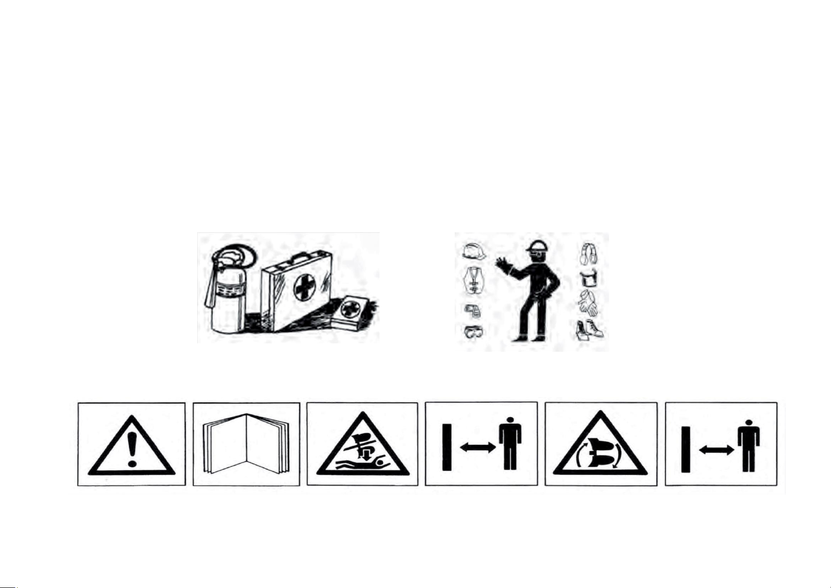
1.-Comply with the instructions given by the danger signals exposed
in this handbook (Fig.1) and affixed to the plough itself.
2.-Operations and adjustments to the implement must always be
carried out when the engine is off and the tractor braked.
3.-It is absolutely forbidden to carry passengers or animals on the
plough.
4.-It is absolutely forbidden for persons without a driving license,
inexpert persons or those in precarious health conditions to drive the
tractor with the plough mounted.
5.-Strictly comply with all the recommended accident preventing
measures described in this handbook.
6.-Assembly of an implement on the tractor will shift the weights on
the axles.
7.-Before starting the tractor and plough, always check that all safety
devices guarding transport and use are in perfect conditions.
8.-The instructions labels affixed to the plough give useful advice on
how to prevent accidents.
9.-Always comply with the highway code in force in your country
when travelling on public roads.
10.-Comply with the maximum permissible weight on the axle of the
tractor, the total adjustable weight, transport regulations and the
highway code.
11.-
Always become familiar with the controls and their operation
before starting work.
12.-
Take the utmost care during the plough coupling and release
phases.
13.-Never ever leave the driving seat whilst the tractor is moving.
14.-
Remember that the road holding, steering and breaking capacity
may be notably influenced by the presence of a mounted implement.
15.-
It is absolutely forbidden to stand within the operative range of the
plough.
16.-
Before leaving the tractor, lower the mounted plough coupled to
the lift unit, stop the engine, engage the hand brake and remove the
ignition key from the control panel.
17.-
The category of the implement coupling pins must correspond to
that of the lift coupling.
18.-
Take care when working close to the lift links. This is a very
dangerous area.
19.-
It is absolutely forbidden to stand between the tractor and the
plough, to manoeuvre the outside lift control.
20.-
Set the control lever of the hydraulic lift to the locked position
during road transport with the plough mounted.
21.-
The spare parts must correspond to the requirements established
by the Manufacturer. Use only genuine spare parts.
22.-
The safety transfers must always be perfectly visible. They must
be kept clean and should be replaced if they become illegible.
Replacements are available on request from your local dealer.
23.-
The instruction manual must be kept for as long as the machine
lasts.

4
Fig.1
(Fig.1) WARNING
Thoroughly read the manual before starting to work
DANGER
Do not handle the plough when lifted, danger of flattening. Keep
safety distance.
DANGER
Damage can be caused by the rotation of the plough. Keep safety
distance.
Be prepared in case of emergency
Have near a first aid kit and an extinguisher. Write down the telephone
numbers of doctors, ambulances and firemen and keep them near the
telephone.
Use suitable clothes
Avoid loose clothes and use suitable equipment of security according to the
type of works. The safe handling of the machine requires all the attention of
the operator.
Don’t put on auricular to listen to the radio during the work with the
machine.

5
2. DESCRIPTION AND DATA TECHNICAL
1. HEADSTOCK
2. IDENTIFICATION PLATE
3. DRAW FRAME
4. EYE PIECE
5. TURNOVER CONNECTION
6. ON-LAND ARTICULATION
7. FRAME
8. TELESCOPIC FRAME
9. FRONT WHEEL
10. REAR WHEEL
11. TURN CILINDER
12. MOULBOARD
13. SHARE POINT
14. SHARE
15. VARIO ROD
16. BEAM SUPPORT
IDENTIFICATION PLATE (2)
1
3
4
8
6
5
16
10
9
7
11
14
13
12
15
REMARK: The construction number
that is engraved in the identification
plate must be coincident with the
number engraved on the headstock
support.

6
TECHNICAL FEATURES SS - SL
MODEL WORKING WIDTH (CM)
UNDERBEAM
CLEARANCE
POINT TO POINT CLEARANCE
WEIGHT APROX (KG)
SLF-5
16"-18"-20"-22"
72/78/105
100-105
2520
SLF-6
16"-18"-20"-22"
72/78/105
100-105
2715
SLF-7
16"-18"-20"-22"
72/78/105
100-105
2910
SLF-8
16"-18"-20"-22"
72/78/105
100-105
3920
SSF-5
12"-20"
72/78/105
100-105
2910
SSF-6
12"-20"
72/78/105
100-105
3150
SSF-7
12"-20"
72/78/105
100-105
3395
SSF-8
12"-20"
72/78/105
100-105
3825
SLB-5
16"-18"-20"-22"
72/78
100-105
2950
SLB-6
16"-18"-20"-22"
72/78
100-105
3230
SLB-7
16"-18"-20"-22"
72/78
100-105
3510
SLB-8
16"-18"-20"-22"
72/78
100-105
3980
SSB-5
12"-20"
72/78
100-105
3275
SSB-6
12"-20"
72/78
100-105
3590
SSB-7
12"-20"
72/78
100-105
3905
SSB-8
12"-20"
72/78
100-105
4410
SLH-5
16"-18"-20"-22"
72/78
100-105
2850
SLH-6
16"-18"-20"-22"
72/78
100-105
3110
SLH-7
16"-18"-20"-22"
72/78
100-105
3370
SLH-8
16"-18"-20"-22"
72/78
100-105
3820
SSH-5
12"-20"
72/78
100-105
2150
SSH-6
12"-20"
72/78
100-105
2450
SSH-7
12"-20"
72/78
100-105
3760
SSH-8
12"-20"
72/78
100-105
4260

7
3. PROTECTION SYSTEMS
SHEAR BOLT Protection: In the SSF and SLF models
,
protection is achieved by means of shear bolts (Fig.2). When the
share point meets an obstacle, the shear bolt breaks and permits
the beam to pivot back around its bedding. To continue work,
swing back the beam to its original position and replace the shear
bolt B.
WARNING:
use only genuine shear bolts. Other types of bolts
may offer a difference resistance and serious damage can be
produced. In this case the warranty will be void.
Fig.2
B
The Auto Reset protection systems (leaf spring or hydraulic)
work automatically. When the share meets an obstacle the beam
trips up thus overcoming the obstacle and then returns back to its
original position with no need to stop the tractor. (Fig.3 y 4)
This way all the impacts produced by an uneven field are
absorbed by the protection system thus protecting all the elements
of the plough and of the tractor too.
For the same reason, the Auto Reset protection decreases the
traction effort by not making the tractor overcome every eventual
obstacle.
Fig.3
Fig.4

8
HYDRAULIC models (SSH and SLH).
In order to adapt
the plough to soil conditions, in the hydraulic models the
release pressure can be adjusted by means of injecting (heavy
conditions) or removing (light conditions) oil from the system.
To adjust the working pressure proceed as follows.
- Open valve (Fig.6) to read the current pressure on the
manometer.
- Open valve (Fig.7) placed by the varywidth cylinder (SS
models) or by the first furrow width cylinder (SL models).
Note that the valve is closed when the handle is parallel to
the hose!.
- Act on the corresponding tractor spool valve to increase or
decrease the working pressure.
- Once the working pressure is set, close valves.
Note:
The auto Reset systems from OVLAC are set at the
factory for average conditions. In order to minimize impacts on
both the tractor and the plough, we recommend to work at the
lowest possible pressure. The maximum working pressure for
the hydraulic protection is 140 bar.
Fig.6
Fig.7
LEAFSPRING models (SSB and SLB ):
In heavy
duty conditions one or more leafs can be added to ease
penetration of the plough.
Check that the distance of the arch of the spring is
always 700 ± 2mm (Fig.5).
Fig.5
700+-2 mm

9
Fig.8
E
Fig.9
4. SET TO WORK
4.1 ATTACHING THE PLOUGHT
Before attaching the plough check the following points:
- The lift rods of the tractor must be set to the same length and
height.
- The wheels of the tractor must have the same pressure and it
must be set according to manufacturer´s instructions.
- The lower links must be fixed in a centered position allowing for
a little freedom to prevent side pull.
To attach the plough proceed as follows:
- Attach the lower links to the draw bar.
- Attach the top link so that the shaft E (Fig.8) remains vertical
when working. Attach the top link in the position of the
headstock that allows the maximum verticality when lifting the
front.
- Place the stay P (Fig.9) in its working position P1.
- Connect hydraulic hoses to the tractor hydraulic system.

10
To detach proceed as follows:
- Lower the front part of the plough and act on the wheel so the
tractor is lowered with the coupling bar in a horizontal position.
In this way detaching as well as the next attaching will be much
easier.
- Relieve pressure from the spool valves.
- Remove hydraulic hoses from the tractor
- Set the stay in its stand position P (Fig.10).
- Remove top link and lower links.
4.2 HYDRAULIC CONNECTIONS
In SS
models four double acting spool valves (five if the on-land
option is included ) are needed to operate:
- The turnover system.
- Working depth adjustment.
- First furrow width adjustment.
- Working width.
- In-the-furrow or on-land work.
In the SL models three double acting spool valves (four if the on-
land option is included) are needed to operate:
- The turnover system.
- Working depth adjustment.
- First furrow width adjustment.
- In-the-furrow or on-land work.
Fig.10

11
Fig.11
A
4.3 MOULBOARDS
Before starting work, the paint on the mouldboards should
be removed to avoid that the soil remains adhered. In order to
ease this operation, a special peel-off paint is applied at the
factory.
4.4 FIRST FURROW WIDTH ADJUSTMENT
The first furrow width is adjusted hydraulically by means of the
cylinder A (Fig.11). The longer the ram, the wider the first furrow.

12
B
D
C
Fig.12
Fig.13
4.5 ALLIGNMENT
During work, the plough must run straight and parallel to the working
direction. It is recommended that the inside width between the rear
wheels of the tractor is in the range of 130 –150 cm. To avoid the
lateral pull of the plough it is recommended to allow for a certain lateral
play in the three point linkage. This play must be adjusted the same on
both sides.
4.6 IN-THE-FURROW OR ON-LAND
Changing from working in-the-furrow to on-land is achieved by simply
acting on cylinder B (Fig.12). Before acting on the cylinder pin P must be
removed and placed in hole H.
When working on-land it is strongly recommended to fold the plough
back to the in-the-furrow position before turning the plough.
4.7 WORKING DEPTH
The working depth is adjusted hydraulically by means of the cylinder C
(Fig.13). The maximum working depth is adjusted by means of nut D on
the ram of this cylinder. In order to achieve a proper turn of the soil it is
always advisable that the working width be greater than the working
depth.
P
H

13
4.8 WORKING WIDTH
The "S" series (SSF, SSB and SSH)
features the OVLAC
exclusive system to adjust hydraulically the furrow width –Varilabor -
which allows to choose any working width between 12" (30cm) and
21" (53 cm) by means of the cylinder A (Fig.14). The direction of the
wheel is adjusted automatically. A fine adjustment may be made if
necessary by means of the turnbuckle T. Varying the furrow width
permits to adapt the plough to soil conditions and to the power of the
tractor.
In the “L” series (SLF, SLB and SLH
) the furrow width can be
adjusted manually in steps of 2" (5cm) by means of placing bolt on the
desired position (Fig.15). Positions 1 and 4 correspond to the
minimum and maximum width respectively. The wheel must be set
accordingly with respect to the position of the bodies by means of
turnbuckle T (Fig.16) so that it runs parallel to the working direction.
A
T
Fig.15
Fig.14
Fig.16
T

14
4.9 TURNOVER SYSTEM
The turning of the plow is achieved by acting on the telescopic
hydraulic cylinders E (Fig.17).
Fig.17
E
4.10 OTHER ADJUSTMENTS
Check that the beams work vertically with respect to the field. To
achieve this, make sure that the lifting arms of the tractor are set at the
same length and act on the stop bolts A below the turn over rams (Fig.18)
Fig.18
A

15
V
Fig.19
Fig.20
P
5. TRANSPORT AND PARKING
This plough is transported in “butterfly position”. The valves V
must be closed so that the turn over mechanism is locked (Fig.19).
For transport, the front part of the plough must be lifted until
there is enough clearance between the draw bar and the ground.
The rear part must also be lifted by means of the wheel ram and
then lowered a bit always maintaining an appropriate clearance to
the ground.
Remember the wheel of the plough during transport is rolling
just in between the tractor wheels. Be aware of obstacles on the
way when driving the plough.
The stand P (Fig.20) guarantees a steady position when the
plough is parked. When parking the plough make sure that the
locking pin of the stand is placed in the right hole so that he draw
bar is horizontal. When ploughing the stand must be in the position
marked as P1.

16
6. MAINTENANCE
Retighten all bolts and nuts after the first 8 hours of work, specially
the ones of mouldboards, shares and points. Henceforth, check every 100
hours of work. When putting the plough away, clean and grease
thoroughly the mouldboards to prevent from rusting.
Lubrication: grease the greaser.
Safe maintenance
Be used to the maintenance procedures before carrying out the
works. The working zone must be clean and dry. Don’t carry out any work
of lubrication, repair or adjust with the motor enabled. Keep the hands,
feet and clothes always far from movable components. Turn all the
controls off, to alleviate the pressure. All the components must be in good
state and correctly installed. Repair damages immediately. Change any
worn away or broken pieces. Maintain all the components of the machine
clean of fat, oil and accumulated dirt. Because of being dragged
equipment, disconnect the cable groups of the tractor before making
works of weld in the machine.
Take care of the leaks of high pressure
The fluids that escape of the system can have as much force that
they can penetrate the skin, causing serious injuries. Therefore, it is
essential to leave the system without pressure before relaxing or
disconnecting any pipe and make sure that all the connections and the
hydraulic parts they are well tight before applying pressure to the system.
In order to locate a hydraulic oil leak, use a piece of cardboard that is put
on the connections. Do not approach the hands and the body to a leak of
high pressure. If, in spite of this precaution, it happens an accident, go
immediately to a doctor who should eliminate surgically the fluid within few
hours to avoid gangrene. The doctors who do not have experience in
dealing with these type injuries can go to a specialized medical centre.
Storage of the hydraulic sleeves.
IMPORTANT:
maintain the plugs clean. The abrasive particles, like
the sand or the metallic shaving, can damage the oil seals, shirts and
cylinders, causing internal leaks. Once disconnected of the tractor, make
sure that they are not in contact with the ground

17
Fig.21
1
1
1
1
1
1
1
1
3
2
1
MAINTENANCE PLAN
The points marked in Fig 21 must be greased with the following
periodicity:
1- every 10 working hours
2- every 50 working hours
3- every 100 working hours
As a general rule, all of these points should be greased before and
after every season.

18
6. OPTIONAL EQUIPMENT
The Ploughts SS-SL Ovlac can be equipped with:
6.1 Disc coulters (Fig.22).
6.2 Cover Boards (Fig.23).
6.3 Slatted moulboards (Fig.24).
6.4 Landslide extension (Fig.25)
6.5 Skimboards (Fig.26).
Fig.22
Fig.24
Fig.25
Fig.23
Fig.26

19
CONTENT
HEADSTOCK.........................................................................20
TURNOVER CONNECTION ..................................................24
FOLK .....................................................................................26
FRAME SS.............................................................................28
FRAME SL.............................................................................32
ADDITIONAL BODY..............................................................35
VARYWIDTH SYSTEM..........................................................37
TELESCOPIC FRAME...........................................................39
HYDRAULIC WHEEL ............................................................41
ADVANCED WHEEL .............................................................43
BEAM SUPPORT...................................................................48
HYDRONEUMATIC SYSTEM................................................57
HYDRAULIC ROLLOVER SYSTEM......................................62
HYDRAULIC FOLK SYSTEM................................................63
HYDRAULIC VARYWIDTH SYSTEM ....................................64
HYDRAULIC TELESCOPIC SYSTEM ...................................66
HYDRAULIC WHELL SYSTEM .............................................68
ACCUMULATOR ASSEMBLY WHEEL................................70
SUPL. ELECTRO VALVE......................................................73
BODIES .................................................................................76
SKIMBOARDS.......................................................................84
COVER BOARDS..................................................................88
LANDSLIDE EXTENSION .....................................................90
DISC COULTERS..................................................................93
8. SPARE PARTS
Spare parts should always be ordered from your dealer and should
always include the following indications:
- Type, model and serial number of the plough.
These data are
punched on the identification plate with which every plough is equipped.
- Code number of the required spare part.
This will be found in the
attached spare parts list.
- Description of the part and required quantity.
- Means of delivery
. Transport expenses shall always be at the
consignor's charge.
- NOTE: The terms Right and Left
indicated on the descriptions, refer to
the plough when viewed from the rear. The spare parts components of
waste equipment, as shares, mouldboards, etc., are considered right if
they are mounted on a body which spills the soil to the right side.
- Note about the warranty
: The orders of spare parts in warranty should
always be clearly specified.
The Manufacturer will always sentence if
the spare parts are warranted in their replacement.
- Moreover, the warranty is suppressed if:
- The plough is repaired without authorisation from the
Manufacturer, or spurious spare parts, and inadequate bolts are
mounted.
-
The plough has been used beyond the specified power limit, or
anomalous manoeuvres and operations have been made.

HEADSTOCK
20
This manual suits for next models
25
Table of contents
Other Ovlac Farm Equipment manuals