OWL 7V Series User manual

OWL-INC.COM
Revision 1.0d
Optical Wavelength Laboratories (OWL)
N9623 West US Hwy 12
Whitewater, WI 53190
Phone: 262-473-0643
Internet: OWL-INC.COM
Optical Wavelength Laboratories
OPERATIONS GUIDE
FIBER OWL 7 SERIES
FIBER OPTIC LINK CERTIFIERS
FIBER OWL 7 OPM W/INTEGRATED OPTICAL LENGTH TESTER
F7X Stand-alone certification power meter
F7V Stand-alone certification power meter w/integrated VFL
F7L Stand-alone certification power meter (without length testing)
FIBER OWL 7 SERIES TEST KITS
KF7XMS F7X + quad-wave source (MM: 850/1300nm, SM:1310/1550nm)
KF7XMX F7X + multimode dual-wave source (850/1300nm)
KF7XMV F7X + multimode dual-wave source (850/1300nm) w/integrated VFL
KF7XSX F7X + singlemode dual-wave source (1310/1550nm)
KF7XSV F7X + singlemode dual-wave source (1310/1550nm) w/integrated VFL
FIBER OWL 7V SERIES TEST KITS
KF7VMS F7V + quad-wave source (MM: 850/1300nm, SM:1310/1550nm)
KF7VMX F7V + multimode dual-wave source (850/1300nm)
KF7VMV F7V + multimode dual-wave source (850/1300nm) w/integrated VFL
KF7VSX F7V + singlemode dual-wave source (1310/1550nm)
KF7VSV F7V + singlemode dual-wave source (1310/1550nm) w/integrated VFL
FIBER OWL 7 LITE SERIES TEST KITS (No length testing)
KF7LMS F7L + quad-wave source (MM: 850/1300nm, SM:1310/1550nm)
KF7LMX F7L + multimode dual-wave source (850/1300nm)
KF7LMV F7L + multimode dual-wave source (850/1300nm) w/integrated VFL
KF7LSX F7L + singlemode dual-wave source (1310/1550nm)
KF7LSV F7L + singlemode dual-wave source (1310/1550nm) w/integrated VFL

2
INTRODUCTION
TABLE OF CONTENTS
Introduction
Before You Begin 4
About This Manual 4
Description 5
Applications 5
Precautions 8
Product Label 8
General Features 9
Specifications 9
Optical Ports 10
Test Procedures
CERT MODE 11
LOSS MODE 27
OPM MODE 40
Transmitter Output Power Measurement 42
Receiver Sensitivity Measurement 43
Optical Loss Measurement 44
Continuity 46
Patch Cable Verification 47
Operation/Maintenance
MAIN MENU 49
OPERATIONS MENU 50
CONFIGURE SOURCE 50
SYSTEM INFORMATION 50
ENTER OPM MODE 50
SETUP MENU 51
OPERATING PARAMETERS 51
USER INFORMATION 51
DISPLAY OPTIONS 51
POWER OPTIONS 52
CUSTOM STANDARD 52
UTILITIES MENU 53
SET SYSTEM CLOCK 53
FACTORY RESET 53
WORKING WITH STORED DATA 54
UNIVERSAL PORT 55
CLEANING THE DETECTOR PORT 56
CLEANING THE LIGHT SOURCE/VFL PORT 57
Appendices
WARRANTY INFORMATION 58
CONTACT INFORMATION 58
SUPPORTED CABLING STANDARDS 59
10-GIGABIT ETHERNET STANDARD 59
UPDATING FIRMWARE 60
RE-CHARGING THE DEVICE BATTERY 60
Link Planning Worksheet 61

3
(This page intentionally left blank)

INTRODUCTION
BEFORE YOU BEGIN
All personnel testing optical fibers should be adequately trained in the field of fiber optics before using any fiber optic test equipment.
If the user is not completely familiar with testing fiber optics, they should seek competent training. Such training can be acquired from
a variety of sources, such as local hands-on training classes.
Valuable information about fiber optic testing can also be gathered from reading printed literature carefully or by thoroughly reading
supplied operations manuals.
Fiber optic testers vary from other types of test equipment due to issues such as:
1) standards-based testing
2) proper fiber optic test procedures (FOTPs)
3) "zeroing" or referencing of power levels
4) determining the correct link budget to pass or fail by
Complete understanding of each of these issues is critical for performing proper fiber optic tests.
Throughout this manual you will find various symbols that assist with understanding the procedures outlined in this manual. Below is
a list of these symbols and a short description of their purpose:
Shows a helpful tip that will make a procedure go more smoothly
Tells the user some useful information about the successful completion of a procedure
Warns the operator of a potentially dangerous condition
ABOUT THIS MANUAL
4

INTRODUCTION
Fiber OWL 7 series fiber optic link certifiers are high-accuracy, high-resolution, microprocessor-controlled optical power meters
capable of performing a wide variety of testing applications, from basic optical loss measurement up to dual-wavelength fiber link
certification. With a wide measurement range and NIST-traceable wavelengths, Fiber OWL 7 series certifiers are ideal for both
singlemode and multimode fiber link certification.
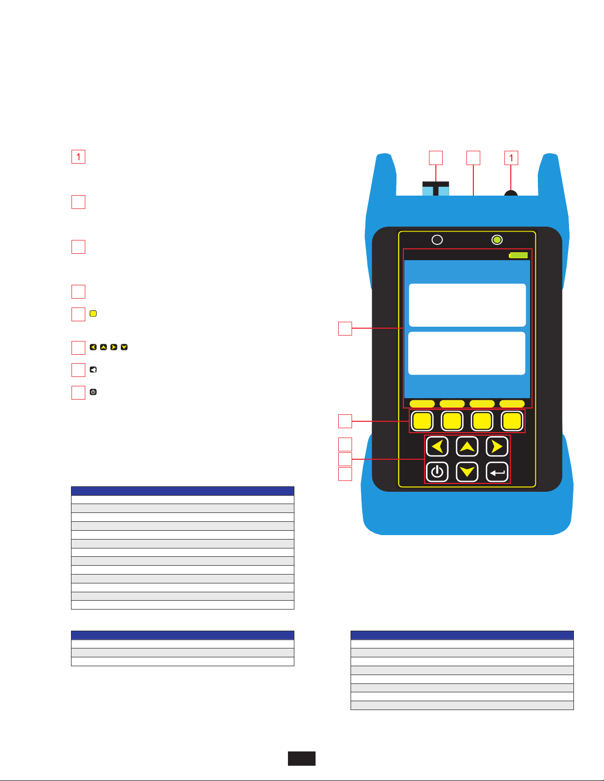
Enclosed in an attractive hand-held case made from high impact plastic and protected by a protective rubber boot, test readings and
graphical help screens can be viewed on the color LCD, and an intuitive 10-key keypad allows for easy data entry.
Each Fiber OWL 7 fiber link certification power meter is powered by a re-chargeable lithium polymer battery, which typically allows up
to 50 hours of continuous use. A built-in auto-shutdown feature further conserves battery life. The battery is re-charged through the
USB port via a supplied battery charger.
The intuitive built-in Link Wizard prompts the user to enter key information used to calculate standards-based link budgets for fiber
optic certification testing, and helpful diagrams guide the user through the setup and testing procedure.
Thousands of data points tored information can be
selectively viewed, re-tested, or deleted from the device.
The data can also be downloaded to OWLView certification software to produce professional-looking formatted certification reports.
OWLView software includes a “tri-report” option that integrates power meter certification, OTDR traces, and endface analysis results
all on the same report.
with descriptive link and fiber run labels can be stored in internal memory. S
DESCRIPTION
5
APPLICATIONS
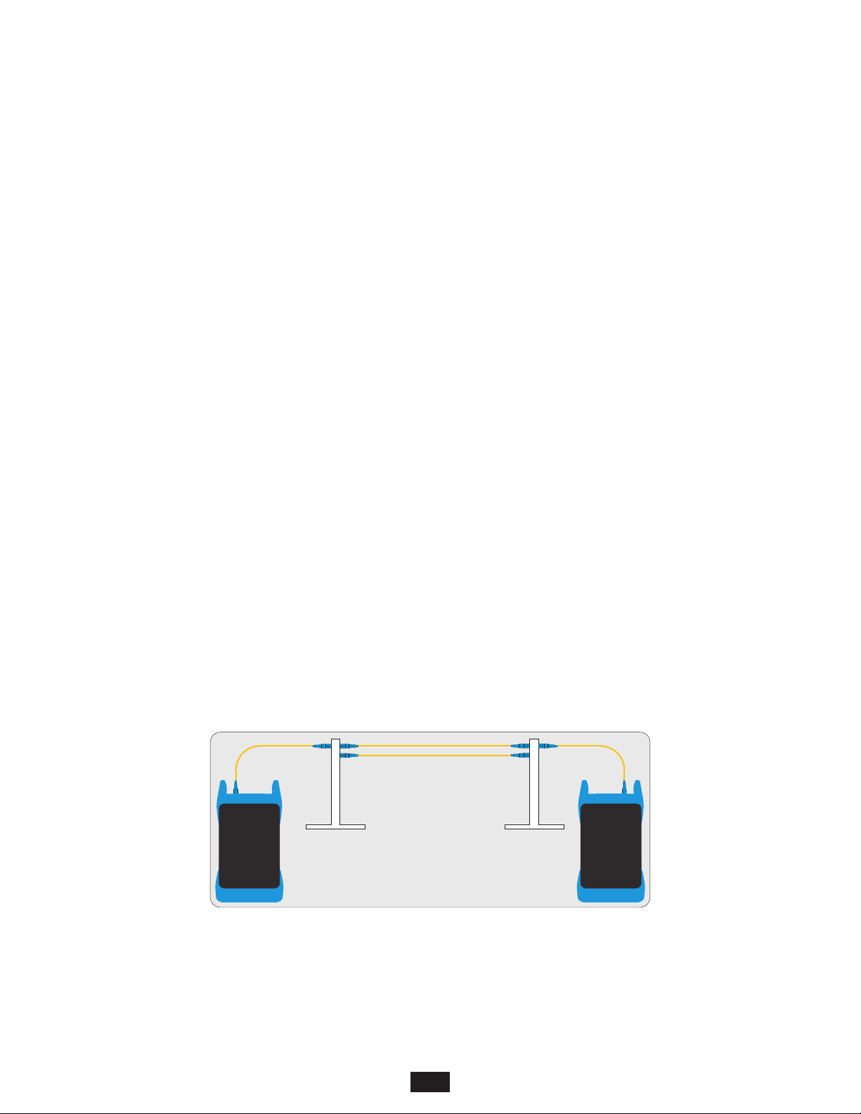
Traditional Fiber Optic Link Certification. When used with a separate stand-alone light source, CERT (certification) mode allows
users to certify individual optical fibers at up to two wavelengths simultaneously. The Link Wizard in the Fiber OWL7 uses attenuation
parameters from popular cabling standards to certify fiber links, and shows a link’s PASS/FAILstatus right in the field.
CERT MODE
SOURCE
Using a meter and a source,
each individual fiber is certified separately.
METER

INTRODUCTION
APPLICATIONS, cont.
Attenuation (Optical Loss) Measurements. After a fiber cable has been installed and terminated, optical loss measurements can
be used to determine if the fiber is installed according to standards and specifications. A comparison between the actual power
measurement and the reference value determines how much optical power is lost through the link.
Optical Power Measurements. Optical power is an absolute measurement of the amount of light intensity; i.e. “brightness”, and can
be measured either at the output of a transmitter (transmit power), or at the input of a receiver (receiver sensitivity). When in OPM
mode, Fiber OWL 7 certifiers can be directly attached to this equipment via a patch cord to check whether the transmitter is within the
manufacturer’s specified power range.
Fiber Continuity Testing. Continuity can be measured with OPM mode in the Fiber OWL 7 by placing a calibrated light source on
one end of the fiber and the meter on the other end. This is also a simple way to measure the attenuation of the fiber.
6
LOSS MODE
SOURCE
Using a meter and a source, technicians can
measure the optical loss of optical fiber links.
METER
FIBER
CONTINUITY
SOURCE
Using a meter and a source, continuity
can be verified.
METER
OPTICAL POWER
MEASUREMENT
Measure
receiver
sensitivity
METERMETER
Measure
transmitter
power

INTRODUCTION
APPLICATIONS, cont.
Optical Fiber Cable Length Measurement. Fiber OWL 7 fiber certifiers can also be used to perform a “round-robin” optical fiber
length measurement. If the unit has an integrated OTDR port, length measurement is done via OTDR trace. (Not included with Fiber
OWL7 LITE optical power meters).
OPTICAL
LENGTH
MEASUREMENT
Measure the end-to-end length of a fiber link
using the loop-back “round-robin” method.
7

INTRODUCTION
PRECAUTIONS
Safety - Exercise caution when working with any optical equipment. High-intensity fiber optic laser sources output potentially
dangerous high energy invisible light, and could cause serious, irreparable damage to the eye. Thus, it is recommended to
look into the connector port of a light source or the end of a fiber.
Operational - It is important to keep connector ferrules and optical connector ports clean. If dirt, dust, and oil are allowed to build up
inside connector ports, irreparable damage may occur to the optics inside the port. For best results, replace dust caps after each use.
Light Source Connector - Do NOT insert APC (Angled Physical Contact) connectors into any light source or OTDR port on your
Fiber OWL7 as this may damage the angled ferrule on theAPC connector.
NEVER
On the back of each Fiber OWL 7 series fiber link certifier are labels similar to the one shown below containing model number, serial
number, power requirements, and special cautionary information.
PRODUCT LABEL
WARNING
MADE IN USA
MODEL#: F7MX
SERIAL#: F7MX99999
POWER: 6V DC, 1A
This product complies with the
following EU Directives:
EN 61326-1:2006
EN 61010-1:2001
Singlemode
1310nm: 0.1 mW
FP Laser
IEC 60825-1
8

Universal Connector Port - includes two adapter caps: 2.5mm for
many popular 2.5mm ferrule connectors, including ST, SC, and FC,
and 1.25mm for LC, MU, and other SFF connectors).
USB Serial Download Port - downloads stored data to a PC using the
supplied USB download cable. Also used for charging re-chargeable
batteries (not included).
Length Test Port - enables Fiber OWL 7 series power meters to
measure cable length. Not included with Fiber OWL 7 LITE optical
power meters.
High-resolution Color LCD Display
- Function keys - activate corresponding menu options shown at
the bottom of the Fiber OWL7 LCD display
- Arrow keys
- Enter key
- Power key
GENERAL FEATURES
FIBER OWL 7 SERIES
OPTICAL POWER METER W/INTEGRATED LENGTH TESTER
(MODEL #s: F7X, F7V)
3
2
4
5
6
7
8
9
TEST ZERO UNITS SAVE
CERT
FIBER#1
ACME CORP / HQ WEST
M=COMPUTER ROOM I=NETWORK HUB 3
Length: 12m WAVE:1310nm
EIA/TIA 568C.3 CON: 2
INDOOR SM SPL: 2
32
4
5
6
7
8
OPTICAL POWER METER PORT
OPTICAL POWER METER
Detector Type
Wavelengths
Measurement Range
Accuracy (Uncertainty)
Display Resolution
Measurement Units
Connector Type
Data Storage Points
Download Port Connection
Software
Modes of Operation
Length Measurement Range
Length Measurement Accuracy
InGaAs
850, 980, 1300, 1310, 1490, 1550, 1625 nm
+5 to -70 dBm
±0.15 dB
0.01 dB
dBm, dB
Universal (2.5 mm and 1.25 mm)
<10,000
USB
OWLView
PAIR, BIDI, CERT, LOSS, OPM
up to 25 km
±2.5 meters
GENERAL
Display Type
Battery Type
Battery Life
Auto-shutdown
Operating Temperature
Storage Temperature
Dimensions
Weight
2.8” Color LCD
Lithium Polymer
up to 50 hours
Yes
-10 to 55° C
-30 to 70° C
2.87” x 4.42” x 1.25”
10 ounces (284 g)
VFL
VFL Output Wavelength
VFL Output Power
VFL Operating Modes
INTEGRATED VFL PORT (OPTIONAL)
650 nm Laser
1 mW
CW, Modulated
SPECIFICATIONS
-0.24
1310nm
PASS by dB1.86
dB
-0.23
1550nm
PASS by dB1.87
dB

OPTICAL POWER METER W/INTEGRATED LENGTH TESTER
FIBER OWL 7 SERIES
OPTICAL PORTS
Model #: F7V
Stand-alone
certification
power meter
w/VFL
Model #: F7X
Stand-alone
certification
power meter
SC LC
10
Model #: F7L
Stand-alone
certification
power meter

CERT MODE
OVERVIEW
TEST PROCEDURES
11
CERT MODE – When used with a separate stand-alone light source, technicians can certify individual optical fibers at up to two
wavelengths simultaneously. The Link Wizard in the Fiber OWL 7 uses attenuation parameters from popular cabling standards to
certify fiber links, and shows a link’s PASS/FAILstatus right in the field.
CERT MODE can be performed with all models of
TEST PROCEDURE
This procedure demonstrates a test procedure that assumes that the fiber link was properly designed, installed, and tested according
to industry standard requirements and recommended “best practices” as shown below:
For non-standard link configurations, such as a patch panel on one end, or “home run” (i.e. no patch panels), technicians may need to
adjust their test procedure and reference method accordingly.
FIBER OWL 7 optical power meter and standalone light source (purchased
separately or as part of a certification test kit).
Patch
Panel
Link Under Test
Patch
Panel
CERT MODE – When used with a separate stand-alone light source, technicians can certify individual optical fibers at up to two
wavelengths simultaneously. The Link Wizard in the Fiber OWL 7 uses attenuation parameters from popular cabling standards to
certify fiber links, and shows a link’s PASS/FAILstatus right in the field.
CERT MODE can be performed with all models of
TEST PROCEDURE
This procedure demonstrates a test procedure that assumes that the fiber link was properly designed, installed, and tested according
to industry standard requirements and recommended “best practices” as shown below:
For non-standard link configurations, such as a patch panel on one end, or “home run” (i.e. no patch panels), technicians may need to
adjust their test procedure and reference method accordingly.
FIBER OWL 7 optical power meter and standalone light source (purchased
separately or as part of a certification test kit).
Link
Under
Test
Patch
Cable
(to active
equipment)
CERT MODE – When used with a separate stand-alone light source, technicians can certify individual optical fibers at up to two
wavelengths simultaneously. The Link Wizard in the Fiber OWL 7 uses attenuation parameters from popular cabling standards to
certify fiber links, and shows a link’s PASS/FAILstatus right in the field.
CERT MODE can be performed with all models of
TEST PROCEDURE
This procedure demonstrates a test procedure that assumes that the fiber link was properly designed, installed, and tested according
to industry standard requirements and recommended “best practices” as shown below:
For non-standard link configurations, such as a patch panel on one end, or “home run” (i.e. no patch panels), technicians may need to
adjust their test procedure and reference method accordingly.
FIBER OWL 7 optical power meter and standalone light source (purchased
separately or as part of a certification test kit).
Interconnection
CERT MODE – When used with a separate stand-alone light source, technicians can certify individual optical fibers at up to two
wavelengths simultaneously. The Link Wizard in the Fiber OWL 7 uses attenuation parameters from popular cabling standards to
certify fiber links, and shows a link’s PASS/FAILstatus right in the field.
CERT MODE can be performed with all models of
TEST PROCEDURE
This procedure demonstrates a test procedure that assumes that the fiber link was properly designed, installed, and tested according
to industry standard requirements and recommended “best practices” as shown below:
For non-standard link configurations, such as a patch panel on one end, or “home run” (i.e. no patch panels), technicians may need to
adjust their test procedure and reference method accordingly.
FIBER OWL 7 optical power meter and standalone light source (purchased
separately or as part of a certification test kit).
an interconnection (i.e. patch panel or wall outlet)
on both ends of the link
1-jumper reference method
(no adapters between meter and source)
CERT MODE
SOURCE
Using a meter and a source,
each individual fiber is certified separately.
METER
Optical Source
WaveSource Pro
AUTO
PORT
MOD
CW
TEST SAVE
CERT
FIBER#1
ACME CORP / HQ WEST
M=COMPUTER ROOM I=NETWORK HUB 3
Length: 100m WAVE:
EIA/TIA 568C.3 CON: 2
INDOOR SM SPL: 2
xxx
X
X
1310
ENTER
-0.24
1310nm
PASS by dB1.86
dB
-0.23
1550nm
PASS by dB1.87
dB

GATHER LINK SETUP INFORMATION
TEST PROCEDURES
12
To make the setup process go more smoothly, have the following information ready in advance. See the appendix for a helpful Link
Setup Worksheet:
LINK NAME – general information about the job (user-definable)
Project Name of the overall project
Location Building or geographic area where the fiber link is located
Meter End End of the fiber link where the meter unit will be used
Source End End of the fiber link where the light source unit will be used
FIBER TESTMODE – how to go about testing the fiber link
Test Mode CERT
Standard Cabling standard used for the certification test; most technicians will use EIA/TIA568C.3
TEST CORD TYPE – defines inter-connection loss at the very ends of the fiber link .where the test equipment connects in
(patch panels, wall outlets) – Options: REFERENCE-grade or STANDARD-grade
SOURCE PORT refers to the type of test cord attached to the light source
OPM PORT refers to the type of test cord attached to the optical power meter
LINK INFORMATION – physical configuration of the link under test
Fiber Type Type of fiber used in the link under test; options may vary based on chosen cabling standard
(see appendix for a fiber type diagram)
Connections Number of inter-connections in the middle of the link under test (patch panels, other mating
sleeves) NOT including the connections at the far end of the link
Splices Number of splices in the link under test; can be either fusion or mechanical splices
Reference Method 1-jumper reference method
ENCIRCLED FLUX – is EF compliance required for this test: YES or NO (only required for multimode testing)
Consult cabling standard documentation or end user requirements to determine if EF compliance is required; if
so, special mode controller cables will be required for setting the optical reference (aka “zeroing”).
RUN NAME – naming of fiber test results within the job to uniquely identify individual fiber strands
Name The name used to identify the group of individual fiber strands in the link
Number The starting fiber strand number in the link. The number will be automatically
incremented as the test results are saved.
CERT MODE

GATHER EQUIPMENT AND ACCESSORIES
(SINGLEMODE)
TEST PROCEDURES
13
METER
CONNECTOR TYPES MUST MATCH THE TEST EQUIPMENT PORTS
CONNECTOR TYPES MUST MATCH THE LINK UNDER TEST
MATING SLEEVETEST CABLE (2) REFERENCE CABLE (1)
SOURCE
MATING SLEEVE (1)
REFERENCE CABLE (1)
(per light source port)
TEST CABLE (3)TEST CABLE (2) TEST CABLE (4)
(4) SINGLEMODE CABLES
LINK UNDER TEST
METER
TEST CABLE (3)
OPM PORT
TEST CABLE (2)
SM PORT
TEST CABLE (4)
LENGTH TEST
LOOPBACK
SIDE A SIDE B
3
1 2
3
1 2
Loopback cable
at far end
completes the
loop for length
measurement
ACCESSORIES REQUIRED FOR OPTICAL LENGTH MEASUREMENT
Optical Source
WaveSource Pro
AUTO
PORT
MOD
CW
SOURCE
NOTE:
SOURCE AND
REFERENCE
CABLE (1)
NOT USED
FOR LENGTH
MEASUREMENT
CERT MODE
NOTE: length testing accessories not required for F7L (Fiber OWL 7 LITE)

GATHER EQUIPMENT AND ACCESSORIES
(62.5/125µm MULTIMODE OM1)
TEST PROCEDURES
14
MATING SLEEVE (1)
TEST CABLE (3)
(4) 62.5/125 MULTIMODE CABLES
TEST CABLE (4)
TEST CABLE (2)
LINK UNDER TEST
METER
TEST CABLE (3)
OPM PORT
TEST CABLE (2)
SM PORT
TEST CABLE (4)
LENGTH TEST
LOOPBACK
SIDE A SIDE B
3
1 2
3
1 2
Loopback cable
at far end
completes the
loop for length
measurement
ACCESSORIES REQUIRED FOR OPTICAL LENGTH MEASUREMENT
Optical Source
WaveSource Pro
AUTO
PORT
MOD
CW
SOURCE
NOTE:
SOURCE AND
REFERENCE
CABLE (1)
NOT USED
FOR LENGTH
MEASUREMENT
REFERENCE CABLE (1) & 0.7” MANDREL (1)
(per light source port)
– OR –
EF
ENCIRCLED FLUX MODE CONTROLLER CABLE
(per light source port)
CERT MODE
CONNECTOR TYPES MUST MATCH THE TEST EQUIPMENT PORTS
CONNECTOR TYPES MUST MATCH THE LINK UNDER TEST
MATING SLEEVETEST CABLE (2) REFERENCE CABLE (1)
SOURCE
0.7”
EF
METER
NOTE: length testing accessories not required for F7L (Fiber OWL 7 LITE)

GATHER EQUIPMENT AND ACCESSORIES
(50/125µm MULTIMODE OM2/3/4)
TEST PROCEDURES
15
LINK UNDER TEST
METER
TEST CABLE (3)
OPM PORT
TEST CABLE (2)
SM PORT
TEST CABLE (4)
LENGTH TEST
LOOPBACK
SIDE A SIDE B
3
1 2
3
1 2
Loopback cable
at far end
completes the
loop for length
measurement
ACCESSORIES REQUIRED FOR OPTICAL LENGTH MEASUREMENT
Optical Source
WaveSource Pro
AUTO
PORT
MOD
CW
SOURCE
NOTE:
SOURCE AND
REFERENCE
CABLE (1)
NOT USED
FOR LENGTH
MEASUREMENT
MATING SLEEVE (1)
TEST CABLE (3)
(4) 50/125 MULTIMODE CABLES
TEST CABLE (4)
TEST CABLE (2)
REFERENCE CABLE (1) & 0.7” MANDREL (1)
(per light source port)
– OR –
EF
ENCIRCLED FLUX MODE CONTROLLER CABLE
(per light source port)
CERT MODE
CONNECTOR TYPES MUST MATCH THE TEST EQUIPMENT PORTS
CONNECTOR TYPES MUST MATCH THE LINK UNDER TEST
MATING SLEEVETEST CABLE (2) REFERENCE CABLE (1)
SOURCE
0.9”
EF
METER
NOTE: length testing accessories not required for F7L (Fiber OWL 7 LITE)

CONFIGURE JOB PARAMETERS
TEST PROCEDURES
16
Power on the Fiber OWL 7. Press to CREATE NEW LINK, then
to start link configuration.
STARTUP MENU
RESUME TESTING
CREATE NEW LINK
LOAD STORED LINK
OPM MODE
MAIN MENU
SELECT EXIT
BACK
Start link configuration
LINK INFORMATION
to navigate the entry fields,
and to edit the contents of the
selected field. Press NEXT to continue.
HQ WEST
ACME CORP
WA10
MC
LINK NAME
PROJECT
LOCATION
METER/MASTER END ‘M’
SOURCE/REMOTE END ‘R’
NEXT BACK HELP
FIBER TEST MODE - CERT mode
to navigate the entry fields,
and to select the appropriate setting.
Press NEXT to continue.
FIBER TEST MODE
STANDARD
SOURCE PORT TEST CORDS
OPM PORT TEST CORDS
CERT
EIA/TIA 568C.3
TEST MODE
HELPNEXT BACK
CERT MODE
STANDARD
STANDARD
Note: In LOSS mode the selected
standard is ignored and no
Pass/Fail results are shown.

CONFIGURE JOB PARAMETERS
TEST PROCEDURES
17
LINK PARAMETERS
to navigate the entry fields, and
to edit the contents of the selected
field. Press NEXT to continue.
ENCIRCLED FLUX (multimode only)
select YES if Encircled Flux compliance is
required; select NO if EF compliance is
not required.
LINK INFORMATION
FIBER TYPE
CONNECTIONS:
SPLICES:
REFERENCE
METHOD:
NEXT BACK HELP
000
INDOOR SM
000
1JUMPER
RUN NAME
to navigate the entry fields, and
to edit the contents of the selected
field. Press NEXT to continue.
Will this link be tested using
Encircled Flux Compliant
methods?
YES NO
Encircled Flux Mode
Controlling the output from a
multimode light source port...
...produces a specific
modal output pattern at
the optical power meter...
...ensuring consistent test
results across a broad range
of multimode light sources
Controller Cable
EF
MM
Review the LINK INFORMATION. If the
information is correct, SAVE to continue.
RUN NAME
HELPBACKNEXT
NAME
NUMBER
1
FIBER#
LINK INFORMATION
Project:
Location:
Meter End:
Source End:
Test Mode:
Standard:
Fiber Type:
Connections:
Splices:
Reference Method:
Encircled Flux Compliant:
Fiber Group:
Fiber Number:
ACME CORP
HQ WEST
MC
WA10
CERT
EIA/TIA 568.3-D
Indoor SM
2
2
1 Jumper
No
FIBER#
1
BACKSAVE
CERT MODE

SET REFERENCE
TEST PROCEDURES
18
On the METER, YES to begin the SET
REFERENCE procedure.
Power ON the light source to be used
for the test.
Setting a reference
(aka “zeroing”)
Sets a baseline optical power
level between a power meter
and light source prior to
taking measurements.
The difference between this
reference level and the
link power measurement
is called optical loss.
You must set a zero reference
before testing. Do you wish
to do it now?
YES NO
Connect the appropriate reference cable as shown between the OPM port on the Fiber OWL 7 and
the light source port being used for this test, then press any key on the meter to proceed.
Optical Source
WaveSource Pro
AUTO
PORT
MOD
CW
Using your test reference
cables, please connect the meter
and source as shown and
press any key to proceed.
Optical Source
WaveSource Pro
AUTO
PORT
MOD
CW
CERT MODE

SET REFERENCE
TEST PROCEDURES
19
After a few seconds, the SOURCE REFERENCE POWER will be shown. Press DONE when all
references have been set.
Set the light source to the wavelength shown or AUTO mode if the source is an OWL source that is
capable of AUTO mode (which allows simultaneous dual-wavelength testing).
Press TEST to set the SOURCE REFERENCE POWER.
Optical Source
WaveSource Pro
AUTO
PORT
MOD
CW
Wavelength
Set source to AUTO or 1310nm
You will need to set a source
power reference for each
wavelength that you are testing.
Press TEST to measure.
Press DONE after testing all
wavelengths.
Power Typical
TEST WAVE BACK DONE
SOURCE REFERENCE POWER
HELP
Wavelength
1310nm
1550nm
Set source to AUTO or 1310nm
You will need to set a source
power reference for each
wavelength that you are testing.
Press TEST to measure.
Press DONE after testing all
wavelengths.
TEST WAVE BACK DONE
SOURCE REFERENCE POWER
HELP
xxxPower
-10.21dBm
-10.60dBm
xTypical
-10.00dBm
-10.00dBm
Optical Source
WaveSource Pro
AUTO
PORT
MOD
CW
NOTE: if not using an AUTO
source and a second wavelength
is required, connect a separate
reference cable between the
testers and follow the procedure
for the second wavelength.
CERT MODE

SET REFERENCE
TEST PROCEDURES
20
CERT MODE
This slide explains testing the additional test cable. Press YES to continue.
Optical Source
WaveSource Pro
AUTO
PORT
MOD
CW
You should measure your test
cable loss before testing.
Do you wish to do it now?
042
Checking additional test cable
(dotted line)
The additional test cable is
used to connect the optical
power meter to the link
under test, but is not used
for setting a reference.
Therefore, this test cable
should be checked prior to
testing to ensure it does
not introduce excessive
loss into the final optical
loss measurement.
Connect a mating sleeve to the end of each reference cable, then plug an additional test cable
as shown. Press any key on the meter to proceed.
Optical Source
WaveSource Pro
AUTO
PORT
MOD
CW
Using your test reference
cables, please connect the meter
and injector as shown and
press any key to proceed.
This manual suits for next models
20
Table of contents
Other OWL Test Equipment manuals