OWL Micro OWL 2 Series User manual

Quick Reference Guide
Micro OWL 2 Series
Firmware Version 2.03
Optical Wavelength Laboratories (OWL)
N9623 West US Hwy 12
Whitewater, WI 53190
Phone: 262-473-0643
Internet: OWL-INC.COM
Revision 1.1
26009
Micro OWL 2 Series Test Kits
Certification Testing
Quick Reference Guide
For part numbers:
KIT-M2-D2st
KIT-M2-D2sc
Optical Wavelength Laboratories
e
C
s
i
h
o
W
i
c
e
e
h
i
T
n
-
O
s
p
e
i
t
r
i
c
o
a
t
l
a
r
F
o
i
b
b
e
a
r
L
T
h
e
t
s
g
t
n
E
e
l
q
e
u
v
i
p
a
m
W
e
l
n
a
t
c
i
-
t
p
O
OWL

NOTICE TO NEW USERS:
All personnel testing optical fibers should be adequately trained in the field of fiber optics before using any fiber optic
test equipment.
If the user is not completely familiar with testing fiber optics, they should seek professional training. Such training can
be acquired from a variety of sources, such as local hands-on training classes.
Valuable information about fiber optic testing can also be gathered from reading printed literature carefully or by
thoroughly reading supplied operations manuals.
Fiber optic testers vary from other types of test equipment due to issues such as:
1) standards-based testing
2) proper fiber optic test procedures (FOTPs)
3) "zeroing" or referencing of power levels
4) determining the correct link budget to pass or fail by
Complete understanding of each of these issues is critical for performing proper fiber optic tests.
GETTING STARTED
Thank you for your purchase of this OWL certification test kit. Included in this kit is a Micro OWL 2 optical power meter
and a WaveSource multimode fiber optic light source. This quick reference guide will assist you in setting up your test
kit for a standards-based certification test.
BEFORE YOU TEST
Prior to performing a certification test, there are a few things you need to know about your link:
?Fiber Type
?Fiber Length
?Number of Connections (i.e. patch panels)
?Number of Splices
?Fiber Cabling Standard
?Connector Type
It is also important to understand the definition of a fiber optic link as it pertains to the Micro OWL 2:
A link is a group of fibers that have the same characteristics, and follow the same pathway from one end to
the other.
Also, ensure that your patch cable connectors match the patch panel ports on the link under test.

REQUIRED ACCESSORIES
?(3) multimode patch cables
?mandrel (wrap patch cable 5-7 times around the appropriate mandrel)
0.7” outside diameter for 62.5/125 µm fibers
0.9” outside diameter for 50/125 µm fibers
Multimode reference cables must be wrapped and secured around a mandrel as required by
national and international Fiber Optic Test Procedures (FOTPs). See Figure 1 for a diagram of a
mandrel wrap.
NOTE: if you are testing at both 850nm and 1300nm, each light source wavelength will
require its own mandrel-wrapped patch cable.
EQUIPMENT PORTS
Figure 2 shows the ports of the equipment used during this procedure. These ports may vary depending upon the
model of equipment.
VERIFY PROPER OPERATION OF THE EQUIPMENT
STEP 1 Connect the power meter and light source together with one of the patch cables as shown in Figure 3.
STEP 2 Power on the light source.
STEP 3 Power on the Micro OWL 2.
STEP 4 From the OPERATING MODE menu, select SIMPLE METER.
FIGURE 1
Mandrel Wrap
Detector
Micro OWL 2 power meter
850 nm
1300 nm
FIGURE 2
Test Equipment Ports
Dual OWL light source
FIGURE 3
Connection
for Straight
Patch Cables
LIGHT SOURCE CONNECTOR
PORT NOTES:
– CONNECTOR TYPE MAY VARY
– DO NOT INSERT ANGLED
PHYSICAL CONTACT (APC)
CONNECTOR

STEP 5 Compare the reading on the Micro OWL 2 display to Table 1 for acceptable power levels.
STEP 6 Once proper operation has been verified, remove the first patch cable from both units and set it aside.
STEP 7 Connect the second patch cable between the Micro OWL 2 and the Dual OWL (straight cable – use
Figure 3; mandrel-wrapped cable – use Figure 4).
STEP 8 Compare the reading on the Micro OWL 2 display to Table 1 for acceptable power levels.
STEP 9 Once proper operation has been verified, remove the second patch cable from both units and set it
aside.
STEP 10 Connect a mandrel-wrapped patch cable between the Micro OWL 2 and the Dual OWL as shown in
Figure 4.
STEP 11 Compare the reading on the Micro OWL 2 display to Table 1 for acceptable power levels.
STEP 12 Disconnect this cable from both units, and set it aside. Press <DONE> to return to the OPERATING
MODE menu.
RUN LINK WIZARD
STEP 13 From the OPERATING MODE menu, select CERTIFY LINK.
STEP 14 From the START MENU, press <1>LINK WIZARD.
STEP 15 From the STORED LINKS menu, highlight the stored link name you wish to use and
press <F2> to select.
STEP 16 OPTIONAL: you may change the link name to something that better describes the
group of fibers you are testing.
Press <DONE> to continue.
Core Size
62.5/125 µM
50/125 µM
Replace at
-22.00 dBm
-25.00 dBm
Acceptable Power Level
-19.0 to -22.0 dBm
-22.0 to -25.0 dBm
TABLE 1
FIGURE 4
Connection for
Mandrel-Wrapped
Patch Cables
XXXXXXXXXXXXXXXXXXXXX
X X XXXXXX<1>LINK WIZARD
XX XXXXXXXX<2>MAIN MENU
XXXXXXXXXXXXXXXXXXXXX
XXXXX X XXXXXXSTART MENU
XXXXXXXXXXXXXXXXXXXXX
XX x x xXxxxxxFiber Link 2
x XX XXXXXXXXNEXT SELECT
XX x x xXxxxxxFiber Link 3
XX x x xxXxxxxFiber Link 4
XXXX X XXXXXSTORED LINKS
_____________________
XX x x XxxxxxxFiber Link 1
XXXXXXXXXXXXXXXXXXXXX
x XXX XXX X<--- SHIFT --->
XXXXXXXXXXXXXXXXXXXXX
[Fiber Link 1 ]x x xXxxx
LINK NAME:X XXXXXXXXXXX
_____________________
LIGHT SOURCE CONNECTOR
PORT NOTES:
– CONNECTOR TYPE MAY VARY
– DO NOT INSERT ANGLED
PHYSICAL CONTACT (APC)
CONNECTOR

STEP 17 Change the LINK DATE to the date the fiber will be tested using the format MM-DD-
YY.
Press <DONE> when you are finished entering the current date.
STEP 18 Highlight the cabling standard to use for the set of fibers you are testing.
Press <F2> to select the chosen standard.
STEP 19 Highlight the fiber type of the network under test.
Press <F2> to select the fiber type.
STEP 20 Enter the end-to-end length of the fiber link under test in meters.
Press <DONE> to continue.
STEP 21 Enter the number of connections (i.e. patch panels) in the link under test. Typical fiber
networks will have 2 connections – one for a patch panel located at each end of the link.
Press <DONE> to continue.
STEP 22 Enter the number of splices in the link under test. Splices can be either fusion or
mechanical. Typical multimode networks will have zero splices.
NOTE: some connectors use mechanical splice technology for termination. If the link under
test is terminated with these “no-polish, no-epoxy” type connectors, they should be considered
as mechanical splices.
Press <DONE> to continue.
STEP 23 Review your Link Wizard setup.
If correct, press <F1> and continue on to the next step.
If changes need to be made, press <F3> and go back to STEP 16.
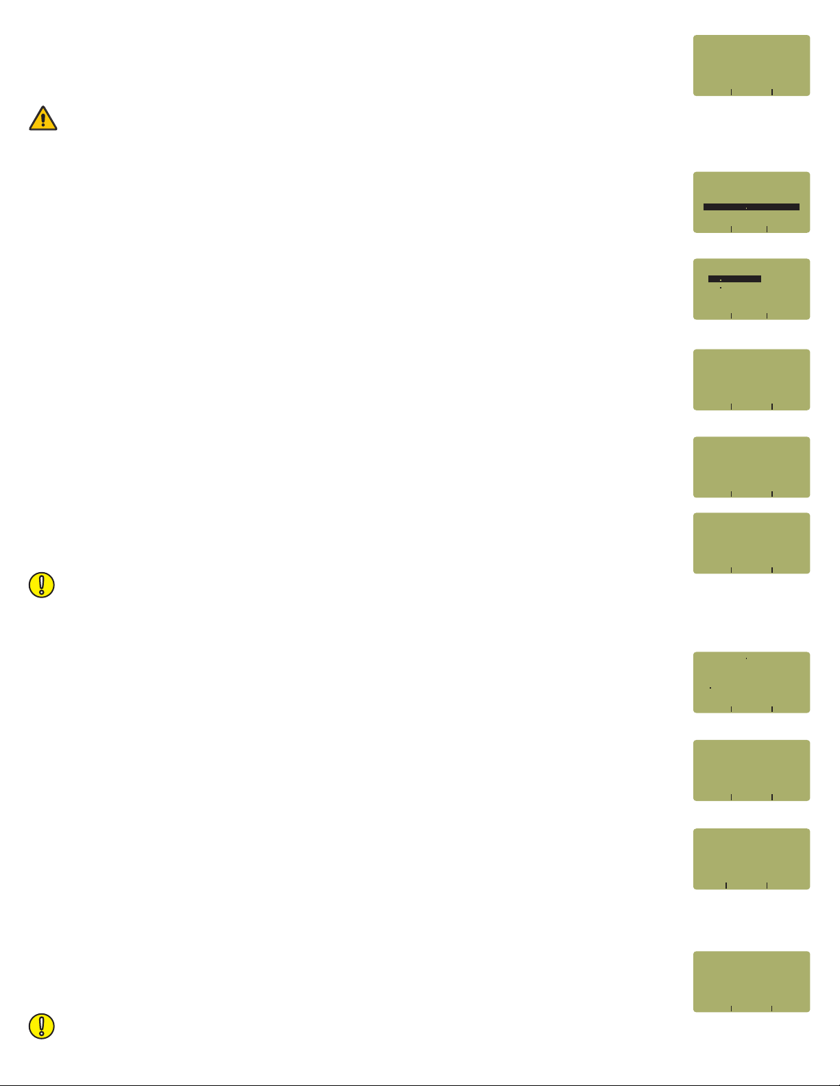
STEP 24 Press <F1> until the asterisk (*) is in front of 850nm (as shown at right).
Press <F2> to begin the SET REFERENCE procedure for 850nm.
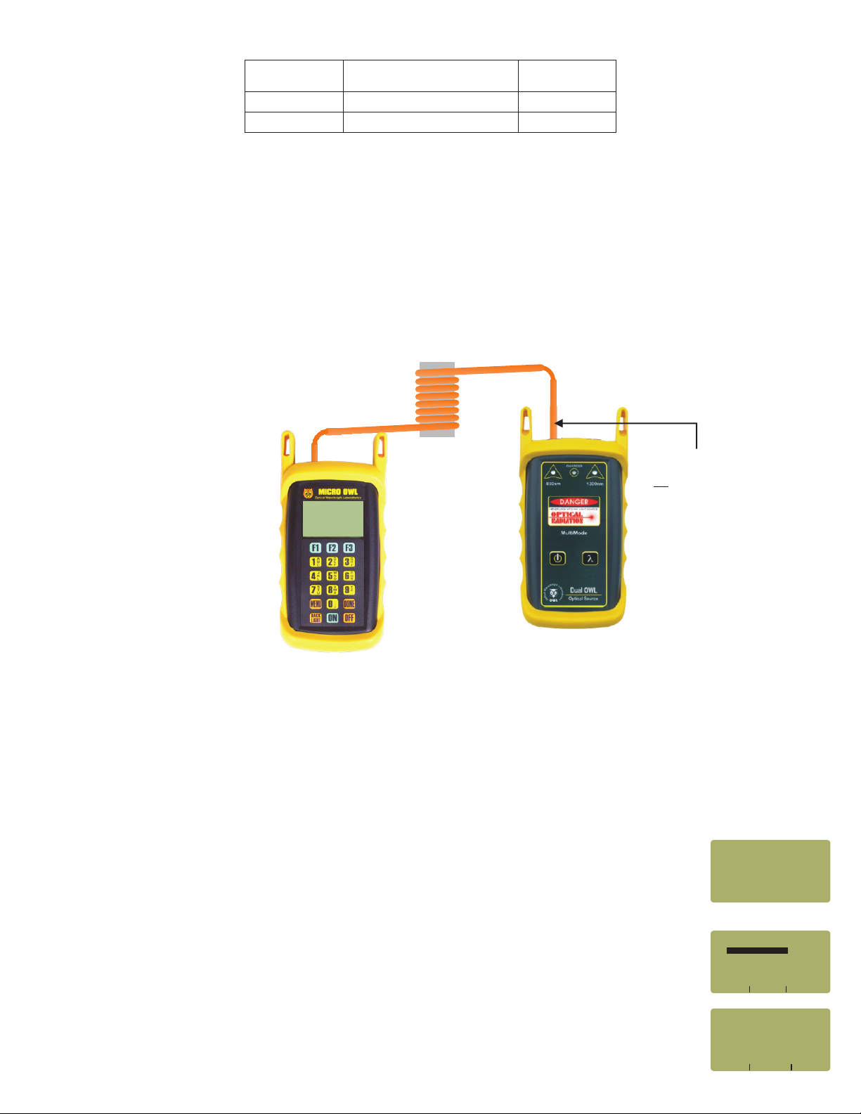
STEP 25 Connect the detector meter and 850nm light source (left-hand port) together with the
mandrel-wrapped cable as shown in Figure 4.
Press <F1> to continue.
STEP 26 Make sure that the 850nm light source port is powered ON and selected (the indicator LED on the left-
hand side will be lit).
STEP 27 Confirm setting the 850nm reference.
Pressing <F1> to continue. You will be returned to the SET SOURCE REFERENCES screen.
NOTE: if you are also testing at 1300nm, you will need to connect a separate mandrel-
wrapped patch cable to the 1300nm port.
It is important to set the current date in order to ensure that the correct date appears on the certification reports.
WAVELEN REF dBmX X
---------------------
* 850nm NOT SETX X X
X XXXX XXXX XWAVE SET DONE
X X X1300nm NOT SET
XXXXXXXXXXXXXXXXXXXXX
SET REFERENCESX
_____________________
XXXXXXXXXXXXXXXXXXXXX
X XXX XXX X<--- SHIFT --->
XXXXXXXXXXXXXXXXXXXXX
[03-20-08]
DATE:X[MM/DD/YY]
_____________________
XXXXXXXXXXXXXXXXXXXXX
X X X XXXXXUSER DEFINED #1
X X X XXXXXUSER DEFINED #2
x XX XXXXXXXXNEXT SELECT
X X XXXXXXXISO/IEC 11801
xx X XXXXFIBER STANDARDS
_____________________
X X XXXXXTIA-568B 3
XXXXXXXXXXXXXXXXXXXXX
XX X X xx50 0um MM
x XX XXXXXXXXNEXT SELECT
xx X xOUTDOOR SM
XXXXX X XXXXXFIBER TYPES
_____________________
XX X xxINDOOR SM
XX X X xxx62 5um MM
[1 TO 65535]X X
XXXXXXXXXXXXXXXXXXXXX
x XXX XXX X<--- --->UNITS
XXXXXXXXXXXXXXXXXXXXX
[01000]X XXMETERS
ENTER FIBER LENGTH:X X XX
_____________________
(A CONNECTION IS WHENX X X
TWO FIBER CONNECTORSX X X
MATE USUALLY A PATCHXX X X
x XXX XXX X<--- --->SHIFT
PANEL)XXXXXXXXXXXXXXX
[2 ]X XXXXXXXXXXXXXXXXX
INLINE CONNECTIONS?X XX
_____________________
SPLICES IN THE FIBERX X X X
BEING TESTED:X XXXXXXXX
XXXXXXXXXXXXXXXXXXXXX
x XXX XXX X<--- --->SHIFT
XXXXXXXXXXXXXXXXXXXXX
[0 ]X XXXXXXXXXXXXXXXXX
ENTER THE NUMBER OFX X X XX
_____________________
01000 Metersx xxxxxxxxx
02 Connectionsx xxxxxxx
00 Splicesx xxxxxxxxxxx
X XXXXXXXXXXXXX XXYES NO
62 5um MMx x
IS THIS CORRECT?X X XXXXX
TIA-568-B 3X XX
_____________________
Standard »
Length »
Connections »
Splices »
Fiber Type »
850nm
DONE
SOURCE
CONNECT
_____________________
XX850nm
X XXXXXXXXXXXXX XXYES NO
xxREF?
_____________________
xxxSET

STEP 28 For setting a 1300nm reference, repeat steps 24 through 27, except you will select
1300nm (as shown at right). Also, make sure that the Dual OWL is set to 1300nm (the right-hand
indicator LED will be lit).
After the 1300nm reference is set, the REF dBm field will be filled in with a reference value.
STEP 29 Press <F3> to complete the Link Wizard.
STEP 30 Press <F1> to begin taking readings.
TAKE READINGS
STEP 31 Disconnect the mandrel-wrapped patch cable from the Micro OWL 2 and take the units to opposite
ends of the link.
STEP 32 Connect the units to the first fiber to test as shown in Figure 5. Your readings will vary from the example
below.
STEP 33 Press <F2> to store the data point. If this is the first data point in the link, you may be prompted to enter
a new label.
STEP 34 Press <F3> to save the data point.
STEP 35 Disconnect the patch cables from the patch panels and move them to the next port in the patch panel,
then repeat steps 33 through 35 until all fibers in the link have been tested at 850nm.
STEP 36 If also testing at 1300nm, repeat steps 32 through 35, but this time use the mandrel-wrapped patch
cable attached to the 1300nm port. Also, make sure that you set the Micro OWL 2 and the Dual OWL to 1300nm.
Do NOT disconnect the patch cable(s) from the light source at any time until all fibers have been tested.
WAVELEN REF dBmX X
---------------------
xX X x850nm -20 00
X XXXX XXXX XWAVE SET DONE
*1300nm NOT SETX X
XXXXXXXXXXXXXXXXXXXXX
SET REFERENCESX
_____________________
12345678910 11 12 12345678910 11 12
FIGURE 5
Equipment
Connection for
Optical Loss
Measurements
UNITS
FIBER
FBR:1
_____________________
STORE
LINK #1
82
68%
dB
WAVE
850nm
- 2 15x x
PASS BY 2 85X XX X
LIGHT SOURCE CONNECTOR
PORT NOTES:
– CONNECTOR TYPE MAY VARY
– DO NOT INSERT ANGLED
PHYSICAL CONTACT (APC)
CONNECTOR
This manual suits for next models
2
Table of contents
Other OWL Test Equipment manuals