manuals.online logo
Brands
  1. Home
  2. •
  3. Brands
  4. •
  5. Ozito
  6. •
  7. Saw
  8. •
  9. Ozito MCS-2355U User manual

Ozito MCS-2355U User manual

Other Ozito Saw manuals

Ozito TSF-1211U User manual

Ozito

Ozito TSF-1211U User manual

Ozito SSB-405 User manual

Ozito

Ozito SSB-405 User manual

Ozito TSB-0808U User manual

Ozito

Ozito TSB-0808U User manual

Ozito TCS-115 User manual

Ozito

Ozito TCS-115 User manual

Ozito PXC PXTBSS-036 User manual

Ozito

Ozito PXC PXTBSS-036 User manual

Ozito OZCS1800WA User manual

Ozito

Ozito OZCS1800WA User manual

Ozito TBS-2000 User manual

Ozito

Ozito TBS-2000 User manual

Ozito SSB-407 User manual

Ozito

Ozito SSB-407 User manual

Ozito OZCS1200WA User manual

Ozito

Ozito OZCS1200WA User manual

Ozito SCMS-2125U User manual

Ozito

Ozito SCMS-2125U User manual

Ozito RSW-5100 User manual

Ozito

Ozito RSW-5100 User manual

Ozito RSG-491VK User manual

Ozito

Ozito RSG-491VK User manual

Ozito CMS-1621U User manual

Ozito

Ozito CMS-1621U User manual

Ozito PXCMSS-210 User manual

Ozito

Ozito PXCMSS-210 User manual

Ozito JSW-6100 User manual

Ozito

Ozito JSW-6100 User manual

Ozito CMSB-1421 User manual

Ozito

Ozito CMSB-1421 User manual

Ozito MCS-2355 User manual

Ozito

Ozito MCS-2355 User manual

Ozito PXCPRS-018 User manual

Ozito

Ozito PXCPRS-018 User manual

Ozito CMS-1621S User manual

Ozito

Ozito CMS-1621S User manual

Ozito SCMS-10STAND User manual

Ozito

Ozito SCMS-10STAND User manual

Ozito PXCPRS-018U User manual

Ozito

Ozito PXCPRS-018U User manual

Ozito BSW-2581 User manual

Ozito

Ozito BSW-2581 User manual

Ozito MSW-3000U User manual

Ozito

Ozito MSW-3000U User manual

Ozito PLS-1214 User manual

Ozito

Ozito PLS-1214 User manual

Popular Saw manuals by other brands

General 90-125 M1 Setup & operation manual

General

General 90-125 M1 Setup & operation manual

Scheppach sd1600v instruction manual

Scheppach

Scheppach sd1600v instruction manual

Skil 5750 Operating/safety instructions

Skil

Skil 5750 Operating/safety instructions

Black & Decker Sawcat 3027-10 owner's manual

Black & Decker

Black & Decker Sawcat 3027-10 owner's manual

Uni-Vent PS-COS12 manual

Uni-Vent

Uni-Vent PS-COS12 manual

Bosch GKS 190 Professional Original instructions

Bosch

Bosch GKS 190 Professional Original instructions

Black & Decker KS999E user guide

Black & Decker

Black & Decker KS999E user guide

Ingco CS18528 instruction manual

Ingco

Ingco CS18528 instruction manual

IMET BS 300/60 SHI Instructions for use

IMET

IMET BS 300/60 SHI Instructions for use

Scheppach Deco-flex instruction manual

Scheppach

Scheppach Deco-flex instruction manual

CMi C-KGS-1450/210 Original instructions

CMi

CMi C-KGS-1450/210 Original instructions

Bosch GCO 14-2 operating instructions

Bosch

Bosch GCO 14-2 operating instructions

Clarke CCS185B Operation & maintenance instructions

Clarke

Clarke CCS185B Operation & maintenance instructions

Makita 2107F instruction manual

Makita

Makita 2107F instruction manual

Holzmann DKS 21PRO user manual

Holzmann

Holzmann DKS 21PRO user manual

RIDGID BS1400 owner's manual

RIDGID

RIDGID BS1400 owner's manual

Optimum OPTisaw CS 275 operating manual

Optimum

Optimum OPTisaw CS 275 operating manual

Makita BPB180 instruction manual

Makita

Makita BPB180 instruction manual

manuals.online logo
manuals.online logoBrands
  • About & Mission
  • Contact us
  • Privacy Policy
  • Terms and Conditions

Copyright 2025 Manuals.Online. All Rights Reserved.

Cutting Disc (fitted)
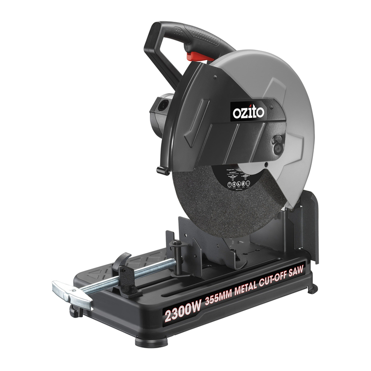
Metal Cut-off Saw
Hex Key
4. Remove the cutting disc
bolt, washer and outer
ange.
5. Cleananygrindingdustfromtheinnerangeand,
after checking that it is in good condition, mount a new
cutting disc onto the spindle.
6. Replacetheouterange,washerandcuttingdiscbolt.
7. Whilst holding the spindle lock
button use the hex key to tighten
the cutting disc bolt in a clockwise
direction.
8. Turn the new cutting disc by
hand, ensuring that it rotates fully
and does not vibrate or oscillate
excessively.
METAL
CUT-OFF SAW
2300W
ORIGINAL INSTRUCTIONS
SPECIFICATIONS
Motor: 2300W
Input: 220
–
240V~50Hz
No Load Speed: 4,000/min
Cutting Disc
Max. Diameter: 355 x 3.2mm
Arbour Size: 25.4mm
Cutting Angle Capacity: -15º to 45º
Max. Cutting Capacities: Round steel 130mm
Square steel 120mm
Rectangle steel 120x130mm
Weight: 16.8kg
MCS-2355U
WHAT’S IN THE BOX
MAINTENANCE DESCRIPTION OF SYMBOLS
WARRANTY
SPARE PARTS
ozito-diy.co.uk

responsible person to ensure that they can use the appliance safely.

WARNING!



  Ensure the guard is in the
maximum cutting disc covering position over the workpiece. Do not use the cutting off
grinders without guards in position.
 
cutting disc. It is important to position your body and the guard to minimize body exposure
from the possible fragments of a disintegrating cutting disc.
 
Cutting discs running over the rated speed
can disintegrate and cause injury.
  This includes face shield,
safety goggles, dust mask and gloves.
  Do not use a cutting
disc that may be damaged. Fragments from a cutting disc that disintegrates during
operation can cause serious injury or property damage.
 
 Proper support of the workpiece is
important to keep the cut-off and over-hanging metal from falling and striking the operator.
 
 Avoid bouncing the cutting disc or giving it rough treatment. If
the cutting disc is damaged due to misuse, it may develop cracks and disintegrate without
warning.
 The cutting disc should have
marked speed equal to or greater than that marked on the machine. Read the operating
instructions supplied by the cutting disc manufacturer.
 These blades are not intended
for this machine and could create loss of control during use or cause injury to persons and
damage to property.
  Cutting wood and plastic could
cause them to burn due to friction heating.
  Dust generated by cutting masonry will clog the motor
causing premature failure and thereby voiding the warranty.
  Sparks from the motor
or cutting may ignite dust and fumes.
 The dust generated when cutting magnesium is
highlyammableandmaybeexplosiveundercertainconditions.
 Excessive accumulation of
powered metal inside the motor housing may cause electrical failures.

The wide vice opening and high pivot point provide cutting capacity for many large pieces. Use
the cutting capacity chart below to determine the maximum size of cuts that can be made with
a new wheel.






Capacity shown on the chart assumes no cutting disc wear and optimum fence position.
CUT-OFF SAW SAFETY WARNINGS
WARNING! 


Read the whole manual carefully and make sure you know how to switch the tool off in an
emergency, before operating the tool.
Save these instructions and other documents supplied with this tool for future reference.
Before you connect the equipment to mains supply make sure that the data on the rating plate are
identical to the mains data.
This tool is double insulated therefore no earth wire is required.

Always use an approved extension lead suitable for the power input of this tool. Before use, inspect
the extension lead for signs of damage, wear and ageing. Replace the extension lead if damaged
or defective.
When using an extension lead on a reel, always unwind the lead completely. Use of an extension
lead not suitable for the power input of the tool or which is damaged or defective may result in a risk
ofreandelectricshock.
WARNING! Failure to follow the
warningsandinstructionsmayresultinelectricshock,reand/orseriousinjury.




a. . Cluttered or dark areas invite accidents.
b.

 Power tools create sparks which may ignite the dust or fumes.
c.  Distractions can cause
you to lose control.

a. 
Unmodiedplugsand
matching outlets will reduce risk of electric shock.
b. 
and refrigerators. There is an increased risk of electric shock if your body is earthed or
grounded.
c.  Water entering a power tool will
increase the risk of electric shock.
d. 
 Damaged or entangled
cords increase the risk of electric shock.
e. 
Use of a cord suitable for outdoor use reduces the risk of electric shock.
f. 
 Use of an RCD reduces the risk of electric shock.
3. Personal safety
a. 


A moment of inattention while operating power tools may result in serious personal injury.
b.  Protective equipment
such as dust mask, non-skid safety shoes, hard hat, or hearing protection used for appropriate
conditions will reduce personal injuries.
c. 
Carrying power
toolswithyourngerontheswitchorenergisingpowertoolsthathavetheswitchoninvites
accidents.
d. 
A wrench or a key left attached to a rotating part of the power tool may result in personal injury.
e.  This enables better control
of the power tool in unexpected situations.
f. 
 Loose clothes, jewellery or long hair can be caught in moving parts.
g. 
ensure these are connected and properly used. Use of dust collection can reduce dust-
related hazards.

a. The correct
power tool will do the job better and safer at the rate for which it was designed.
b.  Any power tool that
cannot be controlled with the switch is dangerous and must be repaired.
c. 
 Such
preventive safety measures reduce the risk of starting the power tool accidentally.
d. 
 Power tools are
dangerous in the hands of untrained users.
e. 

 Many accidents are caused by poorly maintained
power tools.
f. Keep cutting tools sharp and clean. Properly maintained cutting tools with sharp cutting
edges are less likely to bind and are easier to control.
g. 
Use of the
power tool for operations different from those intended could result in a hazardous situation.

a. 
This will ensure that the safety of the power tool is maintained.
b. 
itsserviceagentorsimilarlyqualiedpersonsinordertoavoidahazard.
GENERAL POWER TOOL SAFETY WARNINGS
ELECTRICAL SAFETY
0217
5. REPLACING A DISC cont. 6. GENERAL MAINTENANCE
• Keeptheventilationslotsofthemetalcut-offsawcleanatalltimes
and prevent any foreign matter from entering.
• Ifthehousingofthemetalcut-offsawrequirescleaningdonotuse
solvents but a moist soft cloth only.
• Thegreaseinthegearboxwillrequirereplacement/replenishment
after extensive use of the saw. Please see a power tool repairer to
provide this service.
• Blowdustfromthesawthroughtherearventilationslotswith
compressed air periodically to ensure a dust free tool.

When the carbon brushes wear out, the metal
cut-offsawwillsparkand/orstop.Discontinue
use as soon as this happens.
They should be replaced prior to recommencing
use of the cut-off saw. Carbon brushes are
a wearing component of the cut-off saw and
therefore not covered under warranty.
Continuing to use the cut-off saw when carbon brushes need to be
replaced may cause permanent damage to the tool.
Carbon brushes will wear out after many uses but when the carbon
brushes need to be replaced take the cut-off saw to an electrician or
a power tool repairer for a quick and low cost replacement. Always
replace both carbon brushes at the same time.
 Ozito Industries will not be responsible for any damage or
injuries caused by the repair of the cut-off saw by an unauthorised
person or by mishandling of the cut-off saw.
Transporting the tool
The head lock pin is located on the left side of motor arm to allow the
tool to be transported safely.
To store or transport
the tool, lower the main
handle and push in the
head lock pin.
To release the head lock
pin, push down on the
main handle and pull out
the head lock pin.
Thesawmotorheadarmistted
withahightensionspring.Keephand
pressure on the main handle and slowly
allow the saw head to raise. Cutting Capacity @ 90º
Round 130mm
Square 120mm
Rectangular 120 x 130mm
VHz
~
W
Protective Earthed
n
o
Volts Hertz
Alternating current Watts
/min Revolutions or
reciprocation per minute No load speed
Read instruction manual Wear hearing protection
Wear eye protection
Wear breathing protection
Disconnect from power supply
when performing maintenance
Do not use in raining
Note the rotating direction of the cutting disc!
Double insulation







Blade Bolt
Inner Flange
Outer Flange
Disc
Spindle
Washer
 Unit 9 Stadium Court, Wirral International Business Park, Plantation Road, Bromborough, Wirral, CH62 3QG
All of our products undergo strict quality checks to ensure that they reach
you in perfect condition. In the unlikely event that your device develops a
fault, please contact our service department at the address shown on this
guarantee card. You can also contact us by telephone using the customer
service number shown. Please note the following terms under which
guarantee claims can be made:
1. These warranty terms regulate additional warranty services, which the
manufacturer mentioned below promises to buyers of its new products
in addition to their statutory guarantee claims are not affected by this
guarantee. Our guarantee is free of charge to you.
2. The warranty services only covers defects due to material or
manufacturing faults on a product which you have bought from the
manufacturermentionedbelowarelimitedtoeithertherecticationofsaid
defects on the product or the replacement of the product, whichever we
prefer.
Please note that our devices are not designed for use in commercial, trade
or professional applications. A guarantee contract will not be created if the
device has been used by commercial, trade or industrial business or has
been exposed to similar stresses during the guarantee period.
3. The following are not covered by our guarantee:
- Damage to the device caused by a failure to follow the assembly
instructions or due to incorrect installation, a failure to follow the operating
instructions (for example connecting it to an incorrect mains voltage or
current type) or a failure to follow the maintenance and safety instructions
or by exposing the device to abnormal environmental conditions or by lack
of care and maintenance.
- Damage to the device caused by abuse or incorrect use (for example
overloading the device or the use or unapproved tools or accessories),
ingress of foreign bodies into the device (such as sand, stones or dust,
transport damage), the use of force or damage caused by external forces
(for example by dropping it).
- Damage to the device or parts of the device caused by normal or natural
wear or tear or by normal use of the device.
4. Your Product is guaranteed for a period of 36 months from the original
date of purchase and is intended for DIY (Do It Yourself) use only. Lithium
Ion batteries and chargers are covered by a 12 month warranty. Warranty
excludes consumable parts. Guarantee claims should be submitted
before the end of the guarantee period within two weeks of the defect
being noticed. No guarantee claims will be accepted after the end of the
guarantee period. The original guarantee period remains applicable to the
device even if repairs are carried out or parts are replaced. In such cases,
theworkperformedorpartsttedwillnotresultinanextensionofthe
guarantee period, and no new guarantee will become active for the work
performedorpartstted.Thisalsoappliesifanon-siteserviceisused.
INORDERTOMAKEACLAIMUNDERTHISWARRANTYYOUMUST
RETURNTHEPRODUCTTOTHEPLACEOFPURCHASEWITHYOUR
REGISTER RECEIPT.
Please refer to the restrictions of this warranty concerning wearing parts,
consumables and missing parts as set out in the service information in
these operating instructions.
CUSTOMERSERVICEHELPLINE
GB: 0151 294 4488
IRL: 1850 882711
Ozito-diy.co.uk







3

Scan this QR Code with your
mobile device to take you to
the online manual.
Depth stop
 Ensure that the depth stop is adjusted to the correct height
before commencing operation.
The adjustable depth stop is threaded into the base of the machine at
the rear.
The travel of the cutting disc can be controlled by raising and lowering
the depth stop bolt.
This feature is particularly useful to prevent contact with the work
benchsurfacewhenanewdiscisttedortoincreasedisctravel
as the disc wears.
The depth stop should be checked and adjusted every time
anewdiscistted.
1. Loosen the depth stop with the hex
key supplied.
2. Increase or decrease the height
of the depth stop.
3. Tighten the depth stop knurled lock nut
withyourngers.

1. To change the cutting angle
loosen the two bolts securing
the fence using the hex key
supplied.
2. Move the rear fence to the
desired angle using the scale
as a guide.
3. Tighten the two bolts to secure
the fence in position.
 For accurate cuts, test the cutting angle on some similar scrap
material and adjust the angle to suit your requirements. The scale is
only a guide.

The spacing between the vice and the fence as supplied is 170mm.
When cutting wider materials the rear fence will need to be adjusted to
the rear position. When cutting narrow work pieces the fence should
be positioned in the most forward position.
1. To adjust, loosen and remove
the two bolts securing the
fenceusingtheHexkey.
3. Tighten the two bolts to secure the fence in position.

1. Plug the cordset into the
mains socket.
2. Squeeze the trigger switch to
start the tool.
3. To stop the tool release
the trigger switch.
1. Vice handle
2. Lower guard
3. Cutting disc
4. Upper guard
5. Carry handle
6. Rubber feet
7. Trigger switch
8. Main handle
9. Spindle lock button
10.Lock down pin
11.Depth stop
12.Base
13.Fence
14.Vice
15.Quick release vice lock

KNOW YOUR PRODUCT
1. ADJUSTMENTS 3. OPERATING2. STARTING AND STOPPING 4. HINTS & TIPS 5. REPLACING A DISC

1. Make all adjustments including setting
the vice, fence position and fence angle.
2. Ensure that the work piece is fully
secured before starting metal cutting
operations.
3. Check that the cutting disc, upper
guard, lower guard, head lock pin,
blade access cover and the metal
cutting saw is in good condition.
4. Plug the cordset into the mains
socket.
5. Squeeze the trigger switch to start
the tool.
6. Using the main handle
bring the cutting disc
down onto the work
piece and allow it to
cut its way through
the work piece without
excessive force.
Too much down force
will overheat cutting
disc and reduce cutting
ability or overload the
saw.
7. Oncethecutisnished,raisethemainhandletoclearthecutting
disc from the work piece, release the trigger switch and the cut off
saw will stop.
SETUP & PREPARATION OPERATION MAINTENANCE


• Cuttingdiscselection.Thecuttingdiscmustmatchthematerial
to be cut. There are a wide variety of cutting discs and careful
selection will assist in the correct and safe operation of the saw.
For example, select a bar cutting disc for cutting solid metal
section and a metal stud cutting disc for cutting steel sections.
General purpose metal cutting discs are also available but where
possible it is better to use the correct cutting disc for the task being
performed.
• Theabrasivecuttingdiscswearsoastoconstantlyexposetothe
material being cut clean and sharp cutting edges. This is normal.
• Duringthecuttingoperationapplyaconstantandevenpressureto
the main handle. The cutting disc should be constantly cutting, and
sufcientpressureneedstobeappliedtokeepthecuttingaction
going.Ifinsufcientpressureisapplied,thewheelhasatendency
to clog, and the cutting edges of the disc become blunt and the
cutting process reduces considerably. This is called glazing of the
wheel and is due to the incorrect cutting disc for the material being
cut, or the cutting rate being too slow.
• Donotoverloadthesaw.Thesawshouldrunduringthecutting
operation at close to full speed. Too much pressure being applied
to the tool will slow the motor and can cause motor failure.
• Toomuchpressurebeingappliedtothetoolcanalsocausethe
cutting disc to cut on an angle. Ensure the beginning of the cut is
agradualstartandapplythermandconstantpressureasthecut
gets deeper.
• Whencuttingsections,alwaystryandcutthesectionssoasthe
actual cutting length is as short as possible through the section.
For example, angle iron has two sections to be cut. If the material
is cut where both sections are cut at once, it is better for the cutting
action than trying to cut on thin section and then a long length cut
for the next section. The longer the length of cut, the more chance
of the cutting disc glazing and motor overload.
 As the disc wears the cutting capacity will decrease and the
depth stop may need to be adjusted.
1. Swing the lower guard away to reveal
thecuttingdiscboltandange.
2. Push the spindle lock button and
rotate the cutting disc until the
spindle lock button engages.
3. Whilst holding the spindle lock button
use the hex key (supplied) to remove
the cutting disc bolt
 To remove the cutting disc bolt,
rotate anti-clockwise.













Your Metal Cut-Off Saw is used for cutting steel such as pipe, box
section and steel bars. The saw can cut at angles from -15 to 45º, it
features a three position fence that permits an extended cutting range
whilst the quick release vice allows for fast adjustment. It is intended for
DIY use only.

The vice can be
adjusted quickly by
lifting the quick release
vice lock and pushing
forward or pulling back
on the vice handle.
1. Place your work
piece in between the
fence and vice.
2. Lift the quick release
vice lock and push
the vice forward.
3. Once the vice hits the work piece push
down the quick release vice lock.
4. Rotate the vice handle in a clockwise
direction to secure the work piece in
position.
5. To remove an object from the vice,
rotate the vice handle in an anti-
clockwise direction until the vice jaws
are loose. The work piece can now be
removed.
 The quick release vice lock cannot be lifted until the vice jaws
have been loosened.
MCS-2355U


























2. Move the fence backwards or
forwards to one of the other
twoxingpositions.



1
7 8
2 3 4
5


6 9
10 11 12 13 14 15