Ozito TSB-0808U User manual

EH-Art.-No.: 4340420 I.-No.: 11016
TABLE SAW
800W 200mm
ORIGINAL INSTRUCTIONS
SPECIFICATIONS
Motor: 800W (S2 10 min)
No Load Speed: 2,950/min
Blade: Ø200mm x Ø16 x 2.4mm
Depth Of Cut: 0-45mm
Bevel Angle: 0-45°left
Max. Cutting Capacity:
Bevel 90°: 45mm
Bevel 45°: 35mm
Table Size: 500x3350mm
Dust Port: Ø36
Weight: 13kg
TSB-0808U
WHAT’S IN THE BOX
Push Stick
Table Saw
Rip Fence
Mitre Gauge
WARRANTY
ozito-diy.co.uk
0916
Spanners
OZITO UK Unit 9 Stadium Court, Wirral International Business Park, Plantation Road, Bromborough, Wirral, CH62 3QG
All of our products undergo strict quality checks to ensure that they reach
you in perfect condition. In the unlikely event that your device develops a
fault, please contact our service department at the address shown on this
guarantee card. You can also contact us by telephone using the customer
service number shown. Please note the following terms under which
guarantee claims can be made:
1. These warranty terms regulate additional warranty services, which the
manufacturer mentioned below promises to buyers of its new products
in addition to their statutory guarantee claims are not affected by this
guarantee. Our guarantee is free of charge to you.
2. The warranty services only covers defects due to material or
manufacturing faults on a product which you have bought from the
manufacturer mentioned below are limited to either the rectication of said
defects on the product or the replacement of the product, whichever we
prefer.
Please note that our devices are not designed for use in commercial, trade
or professional applications. A guarantee contract will not be created if the
device has been used by commercial, trade or industrial business or has
been exposed to similar stresses during the guarantee period.
3. The following are not covered by our guarantee:
- Damage to the device caused by a failure to follow the assembly
instructions or due to incorrect installation, a failure to follow the operating
instructions (for example connecting it to an incorrect mains voltage or
current type) or a failure to follow the maintenance and safety instructions
or by exposing the device to abnormal environmental conditions or by lack
of care and maintenance.
- Damage to the device caused by abuse or incorrect use (for example
overloading the device or the use or unapproved tools or accessories),
ingress of foreign bodies into the device (such as sand, stones or dust,
transport damage), the use of force or damage caused by external forces
(for example by dropping it).
- Damage to the device or parts of the device caused by normal or natural
wear or tear or by normal use of the device.
4. Your Product is guaranteed for a period of 36 months from the original
date of purchase and is intended for DIY (Do It Yourself) use only. Lithium
Ion batteries and chargers are covered by a 12 month warranty. Warranty
excludes consumable parts. Guarantee claims should be submitted
before the end of the guarantee period within two weeks of the defect
being noticed. No guarantee claims will be accepted after the end of the
guarantee period. The original guarantee period remains applicable to the
device even if repairs are carried out or parts are replaced. In such cases,
the work performed or parts tted will not result in an extension of the
guarantee period, and no new guarantee will become active for the work
performed or parts tted. This also applies if an on-site service is used.
IN ORDER TO MAKE A CLAIM UNDER THIS WARRANTY YOU MUST
RETURN THE PRODUCT TO THE PLACE OF PURCHASE WITH YOUR
REGISTER RECEIPT.
Please refer to the restrictions of this warranty concerning wearing parts,
consumables and missing parts as set out in the service information in
these operating instructions.
CUSTOMER SERVICE HELPLINE
GB: 0151 294 4488
IRL: 1850 882711
Ozito-diy.co.uk

ONLINE MANUAL
Scan this QR Code with your
mobile device to take you to
the online manual.
1. Integrated Extension Table
2. Folding Legs
3. Push Stick Holder
4. Ext. Table Lock Knob
5. On/Off Safety Switch
6. Overload Protection Reset
7. Blade Guard
8. Bevel Lock Knob
9. Blade Depth Adjustment Knob
10.Bevel Adjustment Handwheel
11. Rip Fence Extrusion
12.Rip Fence Lock Knob
13.Rip Fence Extrusion Locks
TABLE SAW
14.Screw & Cap
15.Mitre Gauge
16.Mitre Gauge Knobs
17.Rip Fence
18.Push Stick
19.Blade Spanner 8mm
20.Blade Spanner 19mm
KNOW YOUR PRODUCT
1. ASSEMBLY
2. Place the rip fence on the table top, either the left or right hand
side of the blade.
3. Now screw the rip fence lock knob through the fence and into
the metal plate on each end.
1. Mount blade guard on the riving knife so that the bolt ts through
the hole in the riving knife.
SETUP & PREPARATION
Blade Guard
Rip Fence
WARNING!: ENSURE THE TOOL IS DISCONNECTED
FROM THE POWER SUPPLY BEFORE ASSEMBLY
Riving
Knife
Bolt
& Nut
Riving
Knife
2. Do not tighten nut too far - the blade guard must be able to
move up and down freely.
Lock
Knob Rip
Fence
Metal
Plate
4. Tighten lock knob to secure in place.
Extrusion
Rip Fence
Nuts
1. Loosen the two nuts sufciently
to allow the extrusion to slide
onto and along the rip fence.

2. SET-UP AND ADJUSTMENTS
1. Loosen both rip fence
lock knobs.
2. Using the scale on the table
top as a guide, slide the rip
fence to the required width.
The depth of cut can be
adjusted by turning the blade
depth knob, anti-clockwise
increases the cutting depth,
clockwise decreases the
cutting depth.
Rip Fence
Note: For mitre cuts the mitre gauge turns to 60° in both directions.
Mitre Gauge
Loosen
Adjust
Angle
Depth Of Cut
Extrusion
Rip Fence
Loosen
WARNING!: ENSURE THE TOOL IS DISCONNECTED
FROM THE POWER SUPPLY BEFORE MAKING ANY
ADJUSTMENTS.
WARNING!: WHEN CUTTING WITH THE MITRE GAUGE
THE LOCKING HANDLE MUST BE FIRMLY TIGHTENED.
Note: The rip fence must be parallel with the saw blade before
being locked into position.
3 Tighten the rip fence lock knobs to clamp the fence in position.
Note: By loosening the 2 rip
fence extrusion locks the fence
extrusion can be removed or
shifted.
Angle Of Cut (Bevel)
1. The mitre gauge is inserted into the table slot from the table’s
front edge.
2. Loosen locking handle and turn the mitre gauge until the arrow
points to the required angle then tighten.
1 Loosen the bevel lock
knob anti-clockwise.
2 Rotate handwheel until the
desired bevel angle is found.
3 To keep the set bevel angle changing during cutting, it must be
locked again by the bevel lock knob. Lock in the bevel position
by rotating lock knob clockwise
Ensure the table saw it set up on a level work bench or sturdy table
The base of the saw has four bench mounting holes (1 each corner,
inside leg) that can be used to mount it to a workbench if desired.
Use four screws or bolts (not included) to secure.
Rip Fence
Extrusion
Note: To extend the mitre
gauge, you can use the fence
extrusion from the rip fence
by using mitre gauge knobs
supplied.
Note: The saw blade’s cutting
height needs to be adjusted to
the workpiece height: the blade
guard shall rest with its front
edge on the workpiece.

TSB-0808U
3.
OPERATING THE TABLE SAW
OPERATION
Push Stick
CAUTION!: DO NOT USE THE TABLE SAW TO CUT
METAL OR MASONRY.
Turning On and Off
1. To turn the table saw ON,
slide the safety stop knob
up and lift the safety cover.
Workpiece
2. Depress the green
button (“I”) to start.
3. To Stop, either depress the red button (“O”) or rmly depress
the safety stop knob.
The push stick protects against accidental contact with the saw
blade.
Overload Protection
In the event of an overload a
thermal overload protection will
trip. Only after the table saw
cools down can it be restarted.
To restart, rst press the
Reset button, then the green
On button (“I”) to restart.
Place the workpiece at
on the table top with one
edge pressed against the
rip fence.
When making a cut push
workpiece in a steady
motion towards the rear
and cut in a single pass.
When cutting using the
mitre gauge, place the
workpiece at on the table
top with one edge pressed
against the mitre gauge.
When making the cut push
mitre gauge forward
Set the saw blade to the required cutting
depth. The blade guard must rest with its
front edge on the workpiece.
Note: Before performing a cut, ensure the blade is at full speed.
Failure to do this will cause the blade to become blunt and cause
the blade to lock-up.

MAINTENANCE
Changing the Blade
1. Ensure the table saw plug is disconnected from the mains power supply.
2. Lower saw blade fully.
3. Remove the side panel by rst removing the 4 screws using a Phillips head
screwdriver
4. Remove the 4 screws from the blade cover then remove the blade cover
from the saw.
5. Using the 8mm spanner provided to hold the
spindle, undo the blade nut by turning anti-
clockwise direction with the 19mm spanner
6. Remove the nut and outer ange.
7. Carefully remove the blade from the shaft.
8. Clean out any dirt or sawdust.
9. Fit the new blade onto the spindle taking care that the inner ange sits
behind the blade.
10. Ret outer ange and nut onto spindle
11. Using the 8mm spanner provided to hold the spindle, tighten the blade nut by
turning clockwise direction with the 19mm spanner
Note: Make sure the saw blade turns freely by turning the blade by hand before
using the saw
11. Repeat steps 3-4 above in reverse order for blade cover & side panel
assembly.
WARNING!: BEFORE CLEANING YOUR TABLE SAW OR
CARRYING OUT ANY MAINTENANCE PROCEDURE,
MAKE SURE THAT THE MOTOR IS OFF AND THE TOOL
DISCONNECTED FROM THE POWER SUPPLY TO PREVENT
ACCIDENTAL STARTING.
CAUTION! NEVER TRY TO USE A BLADE THAT IS LARGER
THAN THE STATED CAPACITY OF THE TABLE SAW. IT MIGHT
COME INTO CONTACT WITH THE BLADE GUARDS AND RISK
PERSONAL INJURY OR DAMAGE TO THE TABLE SAW. THIS
WILL NOT BE COVERED UNDER WARRANTY.
CAUTION! NEVER USE A BLADE THAT IS TOO THICK TO
ALLOW THE OUTER BLADE WASHER TO ENGAGE WITH
THE FLATS ON THE SPINDLE. IT WILL PREVENT THE BLADE
NUT FROM PROPERLY SECURING THE BLADE ONTO THE
SPINDLE.
CAUTION! ENSURE THAT ANY SPACERS AND SPINDLE
RINGS THAT MAY BE REQUIRED SUIT THE SPINDLE AND
BLADE THAT ARE FITTED.
WARNING!: TO ENSURE THE CORRECT BLADE ROTATION
ALWAYS INSTALL THE BLADE WITH THE BLADE TEETH
POINTING IN THE DIRECTION OF ROTATION. ENSURE THE
ARROW DIRECTION ON THE BLADE CORRESPONDS WITH
THE ARROW ON THE BLADE COVER.
Blade Nut
Inner Flange
Outer Flange
Blade
Spindle
Carbon brushes
In case of excessive sparking, have the carbon brushes checked only by a qualied
electrician.Danger! The carbon brushes should not be rep laced by anyone but a
qualied electrician.
Disposal and recycling
The equipment is supplied in packaging to prevent it from being damaged in transit.
The raw materials in this packaging can be reused or recycled. The equipment and
its accessories are made of various types of material, such as metal and plastic.
Never place defective equipment in your household refuse. The equipment should
be taken to a suitable collection center for proper disposal. If you do not know the
whereabouts of such a collection point, you should ask in your local council ofces.
Storage
Store the equipment and accessories in a dark and dry place at above freezing
temperature. The ideal storage temperature is between 5 and 30 °C. Store the
electric tool in its original packaging.
ADDITIONAL INFORMATION
Load factor:
A load factor of S2 10 min (intermittent periodic duty) means that you may operate
the motor continuously at its nominal power level (800 W) for no longer than the
time stipulated on the specications label (10 min). If you fail to observe this time
limit the motor will overheat. During the OFF period the motor will cool again to its
starting temperature.
Danger! Sound and vibration
Sound and vibration values were measured in accordance with EN 61029.
Operation
LpA sound pressure level ........................ 96.6 dB(A)
KpA uncertainty .............................................3 dB
LWA sound power level ........................ 109.6 dB(A)
KWA uncertainty .............................................3 dB
The quoted values are emission values and not necessarily reliable workplace
values. Although there is a correlation between emission and immission levels it is
impossible to draw any certain conclusions as to the need for additional precautions.
Factors with a potential inuence on the actual immission level at the workplace
include the duration of impact, the type of room, and other sources of noise etc.,
e.g. the number of machines and other neighboring operations. Reliable workplace
values may also vary from country to country. With this information the user should
at least be able to make a better assessment of the dangers and risks involved.
Wear ear-muffs.
The impact of noise can cause damage to hearing.
Keep the noise emissions and vibrations to a minimum.
• Only use appliances which are in perfect working order.
• Service and clean the appliance regularly.
• Adapt your working style to suit the appliance.
• Do not overload the appliance.
• Have the appliance serviced whenever necessary.
• Switch the appliance off when it is not in use.
Caution!
Residual risks
Even if you use this electric power tool in accordance with instructions,
certain residual risks cannot be rules out. The following hazards may arise in
connection with the equipment’s construction and layout:
1. Lung damage if no suitable protective dust mask is used.
2. Damage to hearing if no suitable ear protection is used.
Replacing the power cable
Danger!
If the power cable for this equipment is damaged, it must be replaced by the
manufacturer or its after-sales service or similarly trained personnel to avoid danger.
For EU countries only
Never place any electric power tools in your household refuse.
To comply with European Directive 2012/19/EC concerning old electric and electronic
equipment and its implementation in national laws, old electric power tools have to be
separated from other waste and disposed of in an environment-friendly fashion, e.g. by
taking to a recycling depot.
Recycling alternative to the return request:
As an alternative to returning the equipment to the manufacturer, the owner of the
electrical equipment must make sure that the equipment is properly disposed of if he no
longer wants to keep the equipment. The old equipment can be returned to a suitable
collection point that will dispose of the equipment in accordance with the national recycling
and waste disposal regulations. This does not apply to any accessories or aids without
electrical components supplied with the old equipment.

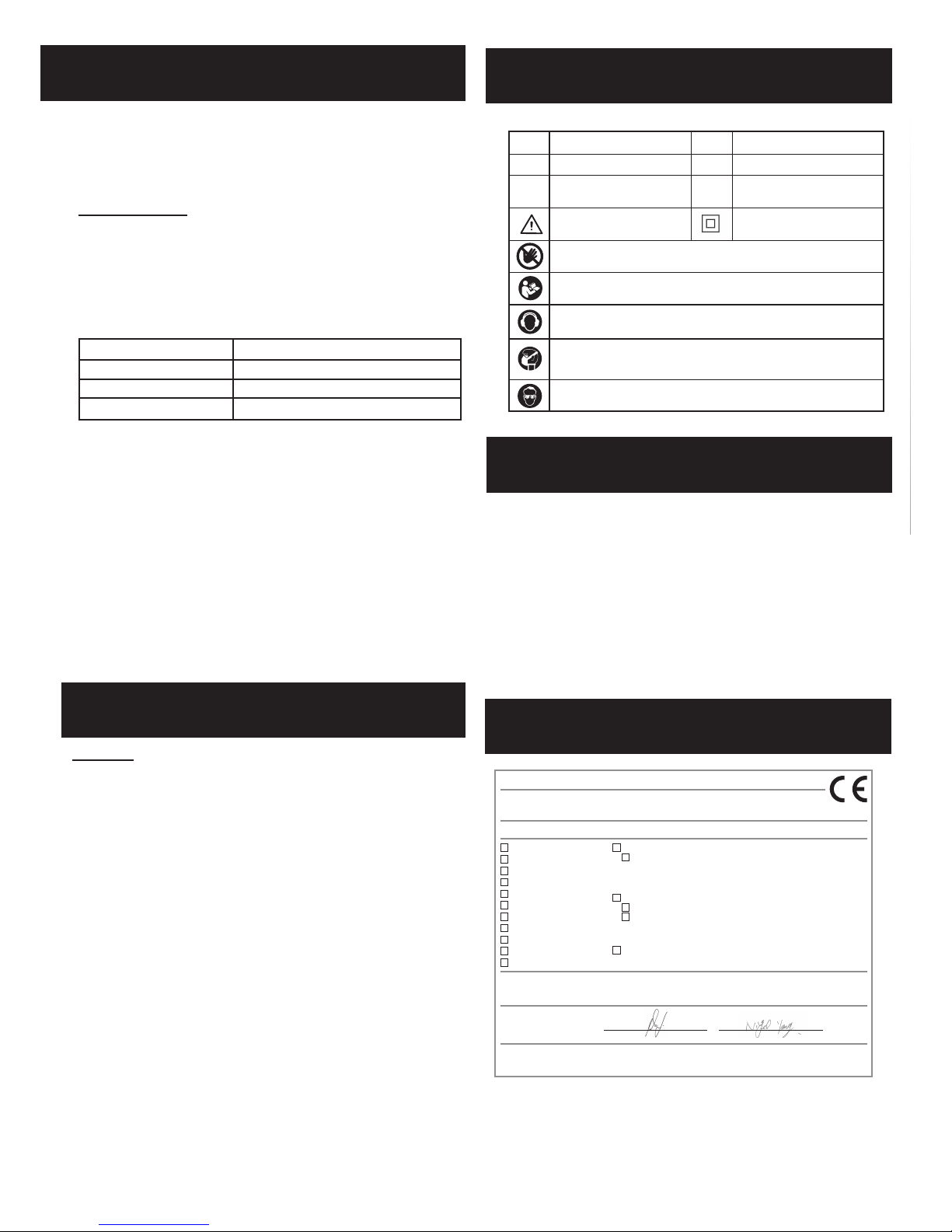
DESCRIPTION OF SYMBOLS
SPARE PARTS
VVolts Hz
~Alternating current W
/min Revolutions or
reciprocation per minute
no
Warning
Caution! Risk of injury! Do not reach into the running saw blade.
Danger! - Read the operating instructions to reduce the risk of inquiry.
Caution! Wear a breathing mask. Dust which is injurious to health can be
generated when working on wood and other materials. Never use the device to
work on any materials containing asbestos!
Caution! Wear ear-muffs. The impact of noise can cause damage to hearing.
Caution! Wear safety goggles. Sparks generated during working or splinters,
chips and dust emitted by the device can cause loss of sight.
Hertz
Watts
No load speed
Double insulated
Spare parts can be ordered from the Special Orders Desk
at your local Bunnings Warehouse or Homebase store.
For further information, or any parts visit
www.ozito-diy.co.uk or contact Ozito Customer Service:
Great Britain: 0151 294 4488
Ireland: 1850 882711
E-mail: enquires@ozito-diy.co.uk
DECLARATION OF CONFIRMITY
Yang/Product-ManagementWeichselgartner/General-Manager
- 135 -
explains the following conformity according to EU directives and norms for
the following product
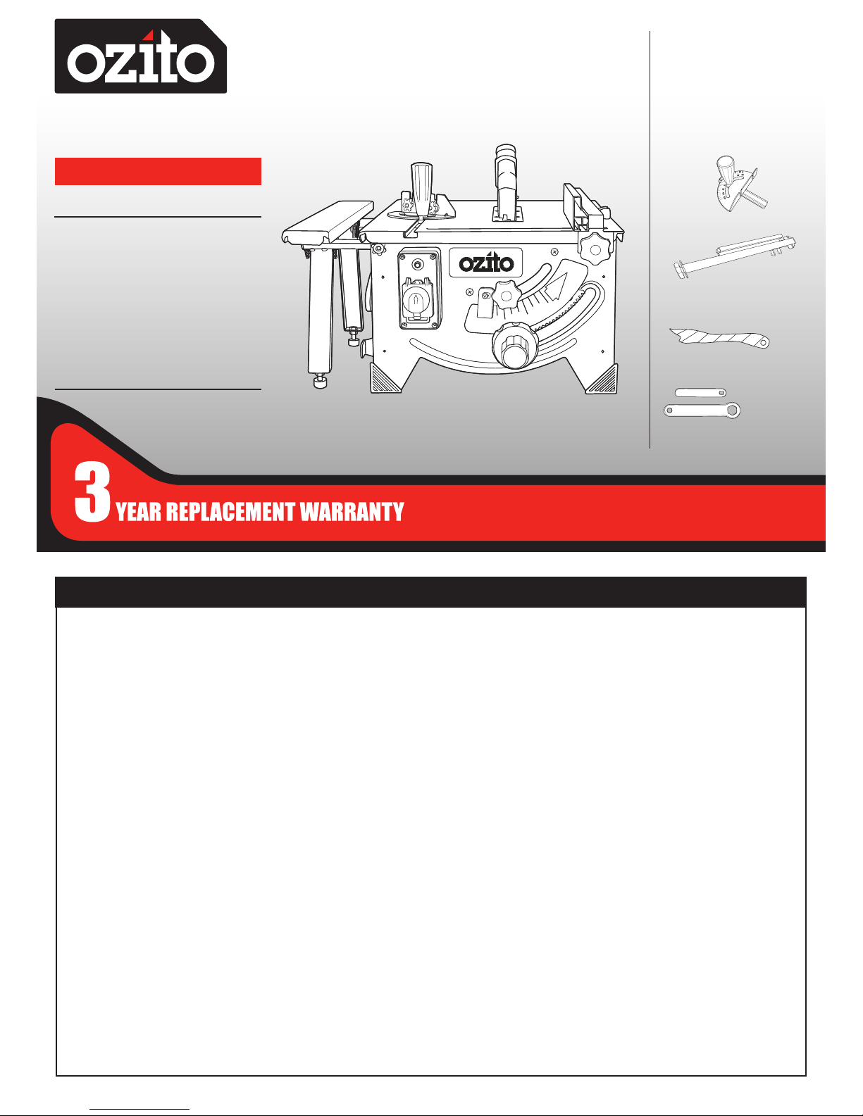
Table Saw TSB-0808U (Ozito)
2014/29/EU
2005/32/EC_2009/125/EC
2014/35/EU
2006/28/EC
X2014/30/EU
2014/32/EU
2014/53/EC
2014/68/EU
90/396/EC_2009/142/EC
89/686/EC_96/58/EC
X2011/65/EU
X2006/42/EC
XAnnex IV
Notied Body: TÜV Süd Product Service GmbH
Ridlerstraße 65, D-80339 München, Germany
Notied Body No.: 0123
Reg. No.: xxx xx xx xxxxx xxxxx
2000/14/EC_2005/88/EC
Annex V
Annex VI
Noise: measured LWA = dB (A); guaranteed LWA = dB (A)
P = KW; L/Ø = cm
Notied Body:
2012/46/EU
Emission No.:
Standard references: EN 61029-1; EN 61029-2-1; EN 55014-1;
EN 55014-2; EN 61000-3-2; EN 61000-3-3
Landau/Isar, den 25.08.2016
First CE: 16 Archive-File/Record: NAPR014443
Art.-No.: 43.404.20 I.-No.: 11016 Documents registrar: R. Gehard
Subject to change without notice Wiesenweg 22, D-94405 Landau/Isar
ISC GmbH · Eschenstraße 6 · D-94405 Landau/Isar
The reprinting or reproduction by any other means, in whole or in part, of
documentation and papers accompanying products is permitted only with the
express consent of the iSC GmbH.
Subject to technical changes
Service information
We have competent service partners in all countries named on the guarantee
certicate whose contact details can also be found on the guarantee certicate.
These partners will help you with all service requests such as repairs, spare and
wearing part orders or the purchase of consumables.
Please note that the following parts of this product are subject to normal or
natural wear and that the following parts are therefore also required for use as
consumables.
Category Example
Wear parts* V-belt, carbon brushes, table insert, push stick
Consumables* Saw blade
Missing parts
* Not necessarily included in the scope of delivery!
In the effect of defects or faults, please register the problem on the internet at www.
isc-gmbh.info. Please ensure that you provide a precise description of the problem
and answer the following questions in all cases:
• Did the equipment work at all or was it defective from the beginning?
• Did you notice anything (symptom or defect) prior to the failure?
• What malfunction does the equipment have in your opinion (main symptom)?
Describe this malfunction.
PROPER USE
Proper use
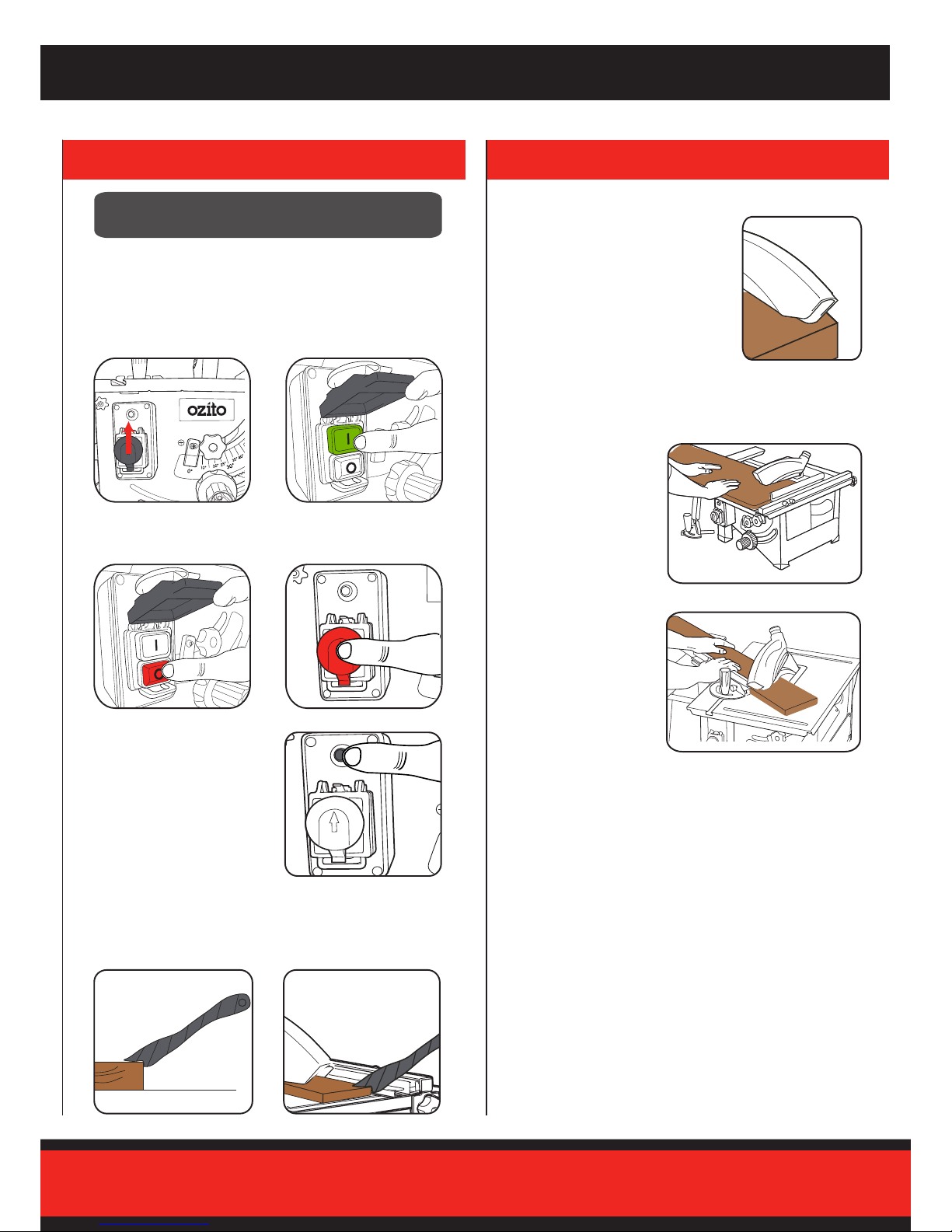
The bench-type circular saw is designed for the slitting and cross-cutting (only with
the cross stop) of all types of timber commensurate with the machine‘s size. The
equipment is not to be used for cutting any type of round wood.
The equipment is to be used only for its prescribed purpose. Any other use is deemed
to be a case of misuse. The user / operator and not the manufacturer will be liable for
any damage or injuries of any kind caused as a result of this.
Please note that our equipment has not been designed for use in commercial,
trade or industrial applications. Our warranty will be voided if the machine is used in
commercial, trade or industrial businesses or for equivalent purposes.
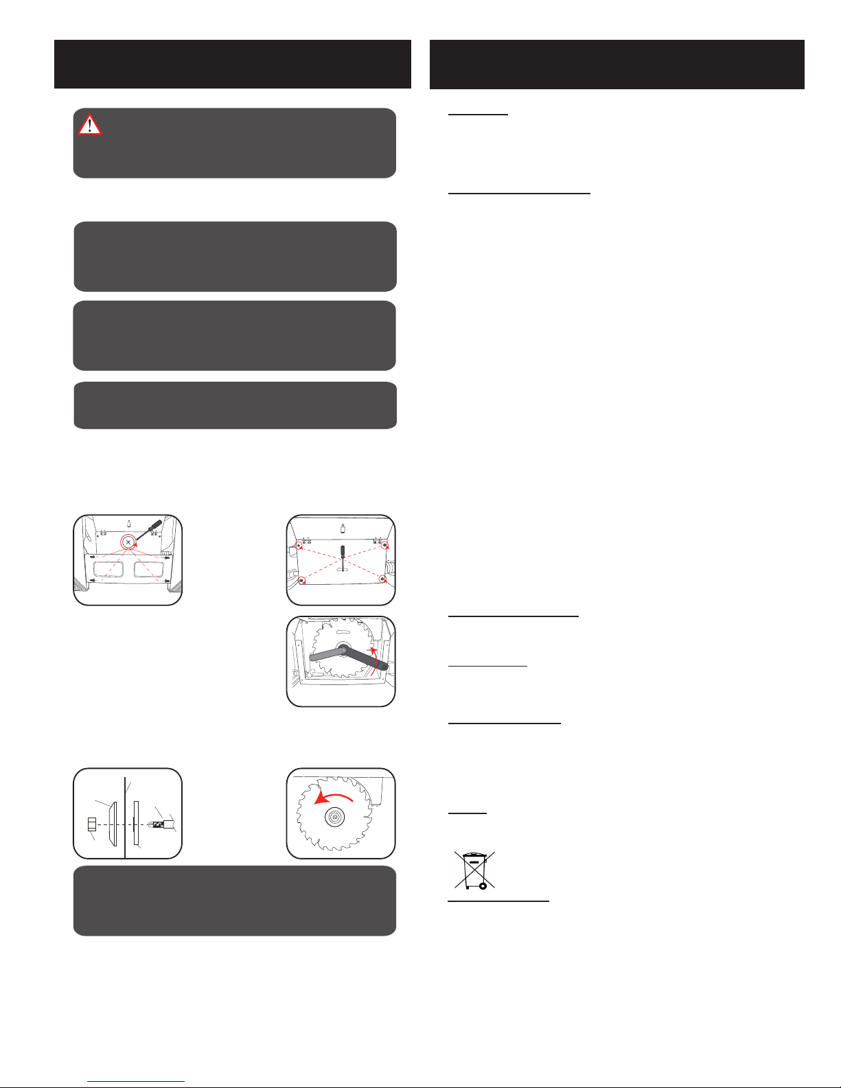
The equipment is to be operated only with suitable saw blades (saw blades made of
HM or CV) It is prohibited to use any type of HSS saw blade and cutting-off wheel.
To use the equipment properly you must also observe the safety information, the
assembly instructions and the operating instructions to be found in this manual.
All persons who use and service the equipment have to be acquainted with these
operating instructions and must be informed about the equipment‘s potential hazards.
It is also imperative to observe the accident prevention regulations in force in your
area. The same applies for the general rules of health and safety at work. The
manufacturer will not be liable for any changes made to the equipment nor for any
damage resulting from such changes. Even when the equipment is used as prescribed
it is still impossible to eliminate certain residual risk factors. The following hazards may
arise in connection with the machine‘s construction and design:
• Contact with the saw blade in the uncovered saw zone.
• Reaching into the running saw blade (cut injuries).
• Kick-back of workpieces and parts of workpieces.
• Saw blade fracturing.
• Catapulting of faulty carbide tips from the saw blade.
• Damage to hearing if essential ear-muffs are not used.
• Harmful emissions of wood dust when used in closed rooms.
Other manuals for TSB-0808U
1
Table of contents
Other Ozito Saw manuals

Ozito
Ozito TBS-2010 User manual

Ozito
Ozito SCMS-1621 User manual

Ozito
Ozito OZSCMS1600WA User manual

Ozito
Ozito SCMS-2125U User manual

Ozito
Ozito RSW-5200U User manual

Ozito
Ozito OZSCMS1600WA User manual

Ozito
Ozito CMS-1810 User manual

Ozito
Ozito JSW-6100 User manual

Ozito
Ozito SCMS-1621 User manual

Ozito
Ozito CMS-1621U User manual

Ozito
Ozito UMS-1810 S User manual

Ozito
Ozito MCS-2355 User manual

Ozito
Ozito RSR-850 User manual

Ozito
Ozito SCMS-8MSS User manual

Ozito
Ozito Power X Change PXBCSS-184 User manual

Ozito
Ozito CMS-210 User manual

Ozito
Ozito SCMS-10STAND User manual

Ozito
Ozito TSF-1211U User manual

Ozito
Ozito CMS-210 User manual

Ozito
Ozito PXC PXSMSS-036 User manual