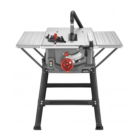
Ozito TSF-1211U User manual

TABLE SAW
2000W 250mm
ORIGINAL INSTRUCTIONS
SPECIFICATIONS
Motor: 2000W (S6 25%) 1800W (S1)
No Load Speed: 5,000/min
Blade: Ø250mm x Ø30 x 2.8mm
Bevel Angle: 0º-45° left
Blade Height Adj: 0-85mm
Max. Cutting Capacity:
Bevel 90°: 85mm
Bevel 45°: 65mm
Table Size: 640 x 490mm
With Side Ext.: 640 x 940mm
Rear Extension: 225 x 490mm
Dust Port: Ø36mm
Weight: 20kg
TSF-1211U
WHAT’S IN THE BOX
WARRANTY
ozito-diy.co.uk
0816
Base Frame Legs x 4,
Cross Struts x 4, Feet x 4
Push Stick
Sliding Mitre
Gauge
Blade Guard & Dust Extractor
Hose, Stabilizing Brackets x 2
Table Extensions x 3
Support Struts x 6
Bolts, Spring & Flat Washers,
Nuts x 32, Spanners x 2
0º 5º
10º
15º
20º
25º
22.5º
30º
45º
Rip Fence
OZITO UK Unit 9 Stadium Court, Wirral International Business Park, Plantation Road, Bromborough, Wirral, CH62 3QG
All of our products undergo strict quality checks to ensure that they reach
you in perfect condition. In the unlikely event that your device develops a
fault, please contact our service department at the address shown on this
guarantee card. You can also contact us by telephone using the customer
service number shown. Please note the following terms under which
guarantee claims can be made:
1. These warranty terms regulate additional warranty services, which the
manufacturer mentioned below promises to buyers of its new products
in addition to their statutory guarantee claims are not affected by this
guarantee. Our guarantee is free of charge to you.
2. The warranty services only covers defects due to material or
manufacturing faults on a product which you have bought from the
manufacturer mentioned below are limited to either the rectication of said
defects on the product or the replacement of the product, whichever we
prefer.
Please note that our devices are not designed for use in commercial, trade
or professional applications. A guarantee contract will not be created if the
device has been used by commercial, trade or industrial business or has
been exposed to similar stresses during the guarantee period.
3. The following are not covered by our guarantee:
- Damage to the device caused by a failure to follow the assembly
instructions or due to incorrect installation, a failure to follow the operating
instructions (for example connecting it to an incorrect mains voltage or
current type) or a failure to follow the maintenance and safety instructions
or by exposing the device to abnormal environmental conditions or by lack
of care and maintenance.
- Damage to the device caused by abuse or incorrect use (for example
overloading the device or the use or unapproved tools or accessories),
ingress of foreign bodies into the device (such as sand, stones or dust,
transport damage), the use of force or damage caused by external forces
(for example by dropping it).
- Damage to the device or parts of the device caused by normal or natural
wear or tear or by normal use of the device.
4. Your Product is guaranteed for a period of 36 months from the original
date of purchase and is intended for DIY (Do It Yourself) use only. Lithium
Ion batteries and chargers are covered by a 12 month warranty. Warranty
excludes consumable parts. Guarantee claims should be submitted
before the end of the guarantee period within two weeks of the defect
being noticed. No guarantee claims will be accepted after the end of the
guarantee period. The original guarantee period remains applicable to the
device even if repairs are carried out or parts are replaced. In such cases,
the work performed or parts tted will not result in an extension of the
guarantee period, and no new guarantee will become active for the work
performed or parts tted. This also applies if an on-site service is used.
IN ORDER TO MAKE A CLAIM UNDER THIS WARRANTY YOU MUST
RETURN THE PRODUCT TO THE PLACE OF PURCHASE WITH YOUR
REGISTER RECEIPT.
Please refer to the restrictions of this warranty concerning wearing parts,
consumables and missing parts as set out in the service information in
these operating instructions.
CUSTOMER SERVICE HELPLINE
GB: 0151 294 4488
IRL: 1850 882711
Ozito-diy.co.uk
EH-Art.-No.: 4340542 I.-No.: 11016

3
ONLINE MANUAL
Scan this QR Code with your
mobile device to take you to
the online manual.
1. Side table extension
2. Rear table extension
3. Sliding mitre gauge
4. Dust extractor hose
5. Blade guard
6. Rip fence
7. Support strut
8. Stabilising bracket
9. Push stick
10. Guide rail
11. Table insert
12. Rip fence lever
13. ON/OFF switch
14. Bevel lock
15. Blade height & Bevel
adjustment
16. Bevel scale
TABLE SAW
KNOW YOUR PRODUCT
54 6
8
1. ADJUSTMENTS
For detailed assembly instruction see Assembly
Manual.
SETUP & PREPARATION
0º 5º
10º
15º
20º
25º
22.5º
30º
45º
32
9
14
7
WARNING! ENSURE THE TOOL IS SWITCHED OFF AND
DISCONNECTED FROM THE POWER SUPPLY BEFORE
PERFORMING ANY OF THE FOLLOWING PROCEDURES.
Cutting Depth
Bevel Angle
1. To lower the blade for a
smaller depth of cut, rotate
the blade height & bevel
adjustment clockwise.
3. Rotate the blade height
& bevel adjustment to the
desired angle using the
bevel scale.
2. Push and hold the blade
height & bevel adjustment
dial in to engage the bevel
gear.
2. To raise the blade for a
larger depth of cut, rotate
the blade height & bevel
adjustment anti-clockwise.
4. Release the blade height & bevel adjustment dial, secure in place by
rotating the bevel lock clockwise.
1. Loosen the bevel lock by
rotating anti-clockwise.
12
13 15 16
11
10

2. SETTING THE RIP FENCE
Rip Fence Stop Height
Thin Material Thick Material
The rip fence supplied with the table saw has two different guide faces.
1 for thick material and 1 for thin material.
2. Slide the stop rail off and
re-insert the desired rail.
1. To change the stop
rail, loosen the 2
wing nuts.
3. Tighten the 2 wing nuts to lock in place.
Note: Rule of thumb: The rear end of the stop comes up against an
imaginary line that begins roughly at the centre of the blade and runs
at an angle of 45° to the rear.
1. Set the required cutting
width.
2. Loosen the wing nuts and
push the stop rail forward
until it touches the imaginary
45° line.
3. Retighten the wing nuts.
Rip Fence Cutting Width
2. Slide the rip fence
to the desired
dimension using the
scale of the guide
rail.
0º 5º
10º
15º
20º
25º
22.5º
30º
45º
The rip fence has to be used
when making longitudinal cuts in
wooden work pieces.
The rip fence can be mounted on
either side of the saw table.
1. Loosen the rip fence lever and
insert the fence into the table
guide rail.
3. Tighten the rip fence lever to
lock the rip fence in position.
Setting the Stop Length
450
The stop rail can be moved in a longitudinal direction in order to
prevent the workpiece from becoming jammed.

4. USING THE TABLE SAW
3. SETTING THE MITRE GAUGE
OPERATION
CAUTION! TO REDUCE THE RISK OF ELECTRICAL
SHOCK, THE USE OF A RESIDUAL CURRENT DEVICE
(RATED 30mA OR LESS) IS RECOMMENDED.
Using the Sliding Mitre Gauge
The sliding mitre gauge can be tted into 1 of the 2 grooves in the table
and can be used to easily perform mitre angle cuts.
2. Loosen the knurled screw to
adjust the mitre angle.
4. Lock the mitre angle by
tightening the knurled screw.
1. Slide the rail of the
mitre gauge into 1 of
the grooves of the
table.
3. Rotate the mitre
gauge to the desired
angle using the mitre
scale.
20mm
IMPORTANT! DO NOT PUSH THE MITRE GAUGE STOP
RAIL TOO FAR TOWARD THE BLADE. THE DISTANCE
BETWEEN THE STOP RAIL AND THE BLADE SHOULD BE
APPROX. 20MM.
IMPORTANT! THE BLADE GUARD MUST ALWAYS BE
LOWERED OVER THE WORK PIECE AND MOUNTED
SECURELY BEFORE YOU BEGIN TO CUT.
IMPORTANT! AFTER EVERY NEW ADJUSTMENT WE
RECOMMEND YOU TO MAKE A TRIAL CUT IN ORDER TO
CHECK THE NEW SETTINGS.
On / Off Switch
1. To turn the saw ON, press
the green button "I".
Note: Wait for the blade to
reach its maximum speed
before commencing with the
cut.
2. To turn the saw OFF,
press the red button "0".
Blade Guard
1. The blade guard must be
able to move freely, adjust
if necessary (refer to
Assembly Manual).

Making Longitudinal Cuts / Ripping
Press one edge of the workpiece against the rip fence while the at
side lies on the saw table. The blade guard must always be lowered
over the workpiece.
When you make a longitudinal cut, never adopt a working position that
is in line with the cutting direction.
1. Set the rip fence in accordance with the workpiece height and the
desired width. (See Stop Height, Cutting Width).
2. Switch on the saw by pressing the ON button "I".
3. Place your hands (with
ngers closed ensuring they
will be clear of the blade) at
on the workpiece and push
the workpiece along the rip
fence and into the blade.
4. Guide at the side with your
left or right hand (depending
on the position of the rip
fence) only as far as the front
edge of the blade guard.
5. Always push the workpiece
through to the end of the
riving knife.
6. The off cut piece remains on
the saw table until the blade
is back in its position of rest.
7. Secure long work pieces
against falling off at the end
of the cut (e.g. with a roller
stand etc.) .
5. MAKING A CUT
TSF-1211U
0º 5º
10º
15º
20º
25º
22.5º
30º
45º
0º 5º
10º
15º
20º
25º
22.5º
30º
45º
Cutting Narrow Work Pieces
Making Bevel Cuts
Making Cross Cuts
Bevel cuts must always be done
using the rip fence.
1. Set the blade to the desired
angle. (See Setting the Bevel
Angle)
2. Set the rip fence in accordance
with the workpiece width and
height (see Stop Height)
3. Carry out the cut in accordance
with the workpiece width.
1. Slide the sliding mitre gauge into one of the grooves in the table and
adjust to the required angle (see Sliding Mitre Gauge).
2. Press the workpiece rmly against
the sliding mitre gauge.
3. Switch on the saw by pressing the
ON button "I".
4. Push the sliding mitre gauge and
the workpiece toward the blade
in order to make the cut.
5. Push the sliding mitre gauge
forward until the workpiece is cut
all the way through.
6. Switch off the saw again. Do not remove the off-cut until the blade
has stopped rotating.
IMPORTANT! BE SURE TO USE A PUSH STICK WHEN
MAKING LONGITUDINAL CUTS.
Be sure to use a push stick
when making longitudinal cuts
in work pieces smaller than
120mm in width. A push stick
is supplied with the saw.
Replace a worn or damaged
push stick immediately.
IMPORTANT! DO NOT PUSH THE MITRE GAUGE STOP
RAIL TOO FAR TOWARD THE BLADE. THE DISTANCE
BETWEEN THE STOP RAIL AND THE BLADE SHOULD BE
APPROX. 20MM.

OPERATION
6. ADJUSTING THE RIVING KNIFE 7. BLADE REPLACEMENT
Setting the Riving Knife
2. Remove the blade guard by
removing the screw
5. Raise the riving knife until the
gap between the saw table
and the upper edge of the
riving knife equals approx.
120mm.
6. The clearance between the
blade and the riving knife
should be 3-5 mm.
120mm
3-5mm
1. Set the blade to the
Max cutting depth
by rotating the blade
height adjustment
and setting the bevel
adjustment to 0°.
4. Loosenthexing
screw.
7. Retightenthexingscrewandthenretthetableinsertandblade
guard.
To achieve a cutting height of 85mm the riving knife can be raised to its
maximum height.
Note: The riving knife helps to prevent kickback and should be checked
each time the blade is replaced.
IMPORTANT! TURN THE BLADE BOLT IN THE
DIRECTION OF ROTATION OF THE SAW BLADE.
IMPORTANT! NOTE THE RUNNING DIRECTION. THE
CUTTING ANGLE OF THE TEETH MUST POINT IN
RUNNING DIRECTION, I.E. FORWARDS (SEE THE
ARROW ON THE BLADE GUARD).
WARNING! ENSURE THE TOOL IS SWITCHED OFF AND
DISCONNECTED FROM THE POWER SUPPLY BEFORE
PERFORMING ANY OF THE FOLLOWING PROCEDURES.
3. Unscrew the countersunk
head screw and remove the
table insert.
Fitting / Replacing the Blade
Note: This product is designed for 250mm saw blades for timber
cutting only.
MAINTENANCE
1. Set the blade to the
Max cutting depth
by rotating the blade
height adjustment
and setting the bevel
adjustment to 0°.
2. Remove the blade guard by
removing the screw
3. Unscrew the countersunk
head screw and remove the
table insert.
4. Undo the blade bolt with 10mm
spanner and 21mm spanner on
thebladeouterangetoapply
counter-pressure.Keepngers
and hands away from blade.
Wear leather gloves
5. Takeofftheouterangeandpulltheoldsawbladeofftheinner
angebydroppingthebladeatanangle.
6. Cleanthebladeangethoroughlybeforettingthenewblade.
7 Mount and fasten the new saw blade in reverse order.
8. Retandsettherivingknifeandthesawbladeguard.
9. Check to make sure that all safety devices are properly mounted
and in good working condition before you begin working with the
saw again.

ADDITIONAL INFORMATION
Operating mode S6 25%: Continuous operation with idling (cycle
time 10 minutes). To ensure that the motor does not become
excessively hot it may only be operated for 25% of the cycle at the
specied rating and must then be allowed to idle for 75% of the
cycle.
8. TABLE INSERT
1. To prevent increased likelihood
of injury the table insert should
be changed whenever it is
worn or damaged.
2. Lower the blade then remove
the blade guard.
Changing the table insert
3. Remove the countersunk head
screw.
4. Take out the worn table insert.
5. Totthereplacementtable
insert, proceed in reverse
order.
Danger! Sound and vibration
Sound and vibration values were measured in accordance with EN 61029.
Operation
LpA sound pressure level ........................ 91 dB(A)
KpA uncertainty .............................................3 dB
LWA sound power level ........................ 104 dB(A)
KWA uncertainty .............................................3 dB
The quoted values are emission values and not necessarily reliable workplace
values. Although there is a correlation between emission and immission levels
it is impossible to draw any certain conclusions as to the need for additional
precautions.Factorswithapotentialinuenceontheactualimmissionlevelatthe
workplace include the duration of impact, the type of room, and other sources
of noise etc., e.g. the number of machines and other neighboring operations.
Reliable workplace values may also vary from country to country. With this
information the user should at least be able to make a better assessment of the
dangers and risks involved.
Wear ear-muffs.
The impact of noise can cause damage to hearing.
Keep the noise emissions and vibrations to a minimum.
• Only use appliances which are in perfect working order.
• Service and clean the appliance regularly.
• Adapt your working style to suit the appliance.
• Do not overload the appliance.
• Have the appliance serviced whenever necessary.
• Switch the appliance off when it is not in use.
Caution!
Residual risks
Even if you use this electric power tool in accordance with instructions,
certain residual risks cannot be rules out. The following hazards may arise
in connection with the equipment’s construction and layout:
1. Lung damage if no suitable protective dust mask is used.
2. Damage to hearing if no suitable ear protection is used.
Replacing the power cable
Danger!
If the power cable for this equipment is damaged, it must be replaced by the
manufacturer or its after-sales service or similarly trained personnel to avoid
danger.
Carbon brushes
Incaseofexcessivesparking,havethecarbonbrushescheckedonlybyaqualied
electrician.Danger! The carbon brushes should not be rep laced by anyone but a
qualiedelectrician.
Disposal and recycling
The equipment is supplied in packaging to prevent it from being damaged in transit.
The raw materials in this packaging can be reused or recycled. The equipment and its
accessories are made of various types of material, such as metal and plastic. Never
place defective equipment in your household refuse. The equipment should be taken to a
suitable collection center for proper disposal. If you do not know the whereabouts of such
acollectionpoint,youshouldaskinyourlocalcouncilofces.
Storage
Store the equipment and accessories in a dark and dry place at above freezing
temperature. The ideal storage temperature is between 5 and 30 °C. Store the electric
tool in its original packaging.
For EU countries only
Never place any electric power tools in your household refuse.
To comply with European Directive 2012/19/EC concerning old electric and electronic
equipment and its implementation in national laws, old electric power tools have to be
separated from other waste and disposed of in an environment-friendly fashion, e.g. by
taking to a recycling depot.
Recycling alternative to the return request:
As an alternative to returning the equipment to the manufacturer, the owner of the
electrical equipment must make sure that the equipment is properly disposed of if he no
longer wants to keep the equipment. The old equipment can be returned to a suitable
collection point that will dispose of the equipment in accordance with the national
recycling and waste disposal regulations. This does not apply to any accessories or aids
without electrical components supplied with the old equipment.
The reprinting or reproduction by any other means, in whole or in part, of documentation
and papers accompanying products is permitted only with the express consent of the iSC
GmbH.
Before you connect the equipment to the mains supply make sure that the data on the
rating plate are identical to the mains data.
Subject to technical changes
• The product meets the requirements of EN 61000-3-11 and is subject to special
connection conditions. This means that use of the product at any freely selectable
connection point is not allowed.
• Given unfavorable conditions in the power supply the product can cause the voltage to
uctuatetemporarily.
• The product is intended solely for use at connection points that
a)donotexceedamaximumpermittedsupplyimpedance0.34Ω,or
b) have a continuous current-carrying capacity of the mains of at least 100 A per phase.
• As the user, you are required to ensure, in consultation with your electric power
company if necessary, that the connection point at which you wish to operate the product
meets one of the two requirements,
a) or b), named above.
Service information
Wehavecompetentservicepartnersinallcountriesnamedontheguaranteecerticate
whosecontactdetailscanalsobefoundontheguaranteecerticate.Thesepartnerswill
help you with all service requests such as repairs, spare and wearing part orders or the
purchase of consumables.
Please note that the following parts of this product are subject to normal or natural wear
and that the following parts are therefore also required for use as consumables.
Category Example
Wear parts* V-belt, carbon brushes, table insert, push stick
Consumables* Saw blade
Missing parts
* Not necessarily included in the scope of delivery!
In the effect of defects or faults, please register the problem on the internet at www.
isc-gmbh.info. Please ensure that you provide a precise description of the problem and
answer the following questions in all cases:
• Did the equipment work at all or was it defective from the beginning?
• Did you notice anything (symptom or defect) prior to the failure?
• What malfunction does the equipment have in your opinion (main symptom)?
Describe this malfunction.

DESCRIPTION OF SYMBOLS
SPARE PARTS
VVolts Hz
~Alternating current W
/min Revolutions or
reciprocation per minute
no
Warning
Caution! Risk of injury! Do not reach into the running saw blade.
Danger! - Read the operating instructions to reduce the risk of inquiry.
Caution! Wear a breathing mask. Dust which is injurious to health can be
generated when working on wood and other materials. Never use the device to
work on any materials containing asbestos!
Caution! Wear ear-muffs. The impact of noise can cause damage to hearing.
Caution! Wear safety goggles. Sparks generated during working or splinters,
chips and dust emitted by the device can cause loss of sight.
Hertz
Watts
No load speed
Double insulated
Spare parts can be ordered from the Special Orders Desk at your
local Bunnings Warehouse or Homebase store.
For further information, or any parts visit
www.ozito-diy.co.uk or contact Ozito Customer Service:
Great Britain: 0151 294 4488
Ireland: 1850 882711
E-mail: enquires@ozito-diy.co.uk
Yang/Product-ManagementWeichselgartner/General-Manager
- 135 -
explains the following conformity according to EU directives and norms for
the following product
Table Saw TSF-1211U (Ozito)
2014/29/EU
2005/32/EC_2009/125/EC
2014/35/EU
2006/28/EC
X2014/30/EU
2014/32/EU
2014/53/EC
2014/68/EU
90/396/EC_2009/142/EC
89/686/EC_96/58/EC
X2011/65/EU
X2006/42/EC
XAnnex IV
Notied Body: TÜV Süd Product Service GmbH
Ridlerstraße 65, D-80339 München, Germany
Notied Body No.: 0123
Reg. No.: M6A 16 11 24192 01776
2000/14/EC_2005/88/EC
Annex V
Annex VI
Noise: measured LWA = dB (A); guaranteed LWA = dB (A)
P = KW; L/Ø = cm
Notied Body:
2012/46/EU
Emission No.:
Standard references: EN 61029-1; EN 61029-2-1; EN 55014-1;
EN 55014-2; EN 61000-3-2; EN 61000-3-11
Landau/Isar, den 25.08.2016
First CE: 16 Archive-File/Record: NAPR014441
Art.-No.: 44.405.42 I.-No.: 11016 Documents registrar: R. Gehard
Subject to change without notice Wiesenweg 22, D-94405 Landau/Isar
ISC GmbH · Eschenstraße 6 · D-94405 Landau/Isar
EG_Erkl_TSF_1211U.indd 135 25.11.2016 12:31:10
DECLARATION OF CONFIRMITY
PROPER USE
Proper use
The bench-type circular saw is designed for the slitting and cross-cutting (only with
the cross stop) of all types of timber commensurate with the machine‘s size. The
equipment is not to be used for cutting any type of round wood.
The equipment is to be used only for its prescribed purpose. Any other use is deemed
to be a case of misuse. The user / operator and not the manufacturer will be liable for
any damage or injuries of any kind caused as a result of this.
The equipment is to be operated only with suitable saw blades (saw blades made of
HM or CV) It is prohibited to use any type of HSS saw blade and cutting-off wheel.
To use the equipment properly you must also observe the safety information, the
assembly instructions and the operating instructions to be found in this manual.
All persons who use and service the equipment have to be acquainted with these
operating instructions and must be informed about the equipment‘s potential hazards.
It is also imperative to observe the accident prevention regulations in force in your
area. The same applies for the general rules of health and safety at work. The
manufacturer will not be liable for any changes made to the equipment nor for any
damage resulting from such changes. Even when the equipment is used as prescribed
it is still impossible to eliminate certain residual risk factors. The following hazards may
arise in connection with the machine‘s construction and design:
• Contact with the saw blade in the uncovered saw zone.
• Reaching into the running saw blade (cut injuries).
• Kick-back of workpieces and parts of workpieces.
• Saw blade fracturing.
• Catapulting of faulty carbide tips from the saw blade.
• Damage to hearing if essential ear-muffs are not used.
• Harmful emissions of wood dust when used in closed rooms.
Transport
Transport the device only by lifting on the table. Do never use safety device for
handling or transport.

Danger! When using electric tools, basic safety precautions should always be
followed to reduce the risk of re, electric shock and personal injury, including
the following. Read and follow these instructions before using the equipment
and keep the safety information in a safe place.
1. Keep work area clean
– Cluttered areas and benches invite injuries.
2. Consider work area environment
–
Don‘t expose power tools to rain. Don‘t use power tools in damp or wet locations.
Keep work area well lit. Don‘t use power tools in presence of ammable liquids or
gases.
3. Guard against electric shock
–
Prevent body contact with grounded surfaces (e.g. pipes, radiators, ranges
refrigeratiors).
4. Keep children away
–Do not let visitors contact tool or extension cord. All visitors should be kept away
from work area.
5. Store idle tools
–When not is use, tools should be stored in dry, high, or locked-up place, out of the
reach of children.
6. Don‘t force tool
–It will do the job better and safer at the rate for which it was intended.
7. Use right tool
–Don‘t force small tools or attachments to do the job of heavy duty tool. Don‘t use
tools for purposes not intended: for example, don‘t use circular saw for cutt- ing
tree limbs or logs.
8. Dress properly
–Do not wear loose clothing or jewelry. They can be caught in moving parts. Rubber
gloves and nonskid footwear are recommended when working outdoors. Wear
protective nair covering to contain long hair.
9. Use safety glasses
–Also use face or dust mask if cutting operation is dusty.
10. Don‘t abuse cord
–Never carry tool by cord or yank it to disconnect it from receptacle. Keep cord from
heat, oil and sharp edges.
11. Secure work
–Use clamps or a vise to hold work. It‘s safer than using your hand and it frees both
hands to operate tool.
12. Don‘t overreach
–Keep proper footing and balance at all times.
13. Maintain tools with care
–Keep tools sharp and clean for better and safer performance. Follow instructions
for lubricating and changing accessories. Inspect tool cords periodically and, if
damaged, have repaired by authorized service facility. Inspect extension cords
periodically and replace if damaged. Keep handles dry, clean and free from oil and
grease.
14. Disconnect tools
–When not in use, before servicing, and when changing accessories such as
blades, bits and cutters.
15. Remove adjusting keys and wrenches
–Form the habit of checking to see that keys and adjusting wrenches are removed
from tool before turning it on.
16. Avoid unintentional starting
–Don‘t carry plugged-in tool with nger on switch. Be sure switch is off when
plugging in.
17. Outdoor use extension cords
–When tool is used outdoors, use only extension cords intended for use outdoors
and so marked.
18. Stay alert
–Watch what you are doing. Use common sense. Do not operate tool when you are
tired.
19. Check damaged parts
–Before further use of the tool, a guard or other part that is damaged should be
carefully checked to determine that it will operate properly and perform its intended
function. Check for alignment of moving parts, binding of moving parts, breakage
of parts, mounting, and any other conditions that may affect its operation. A guard
or other part that is damaged should be properly repaired or replaced by an
authorized service center unless otherwise indicated elsewhere in this instructions
manual. Have defective switches replaced by an authorized service center. Do not
use tool if switch does not turn it on and off .
20. Warning
–The use of any other accessory or attachment other than recommended it this
operating instruction or the Einhell catalog may present a risk of personal injury.
21. Have your tool repaired by an expert
–This electric appliance is in accordance with the relevant safety rules repairing
of electric appliances may be carried out only by experts otherwise it may cause
considerable danger for the user.
22. Connect the dust extraction device
Wherever there are facilities for tting a dust extraction system, make sure it is
connected and used.
Do not lose these safety instructions.
TSF-1211U
SAFETY INSTRUCTIONS
When using the equipment, a few safety precautions must be observed to avoid injuries and damage. Please read the complete operating instructions and safety regulations with
due care. Keep this manual in a safe place, so that the information is available at all times. If you give the equipment to any other person, hand over these operating instructions
and safety regulations as well. We cannot accept any liability for damage or accidents which arise due to a failure to follow these instructions and the safety instructions.
DANGER

1. Safety actions
• Blades that are deformed or cracked must not be used.
• If the table insert is worn, replace it.
• Use only blades which are recommended by the manufacturer and comply with
EN 847-1. When changing the blade, make sure that the cutting width is not smaller
and the saw plate not bigger than the thickness of the splitter.
• Make sure that the chosen blade is suitable for the material that is to be cut.
• If necessary, wear suitable personal protection equipment. This could consist of:
- Ear plugs to prevent the risk of damaging your hearing;
- A breathing mask to avoid the risk of inhaling hazardous dust.
- Always wear gloves when handling saw blades and rough materials. Whenever
practicable, saw blades must be carried in a container.
• The following can have an inuence on dust development:
- Worn, damaged or cracked saw blades
- Recommended capacity of the vacuum extraction system: 20 m/s
- Proper guidance of the workpiece • Blades made of high-alloy high-speed steel
(HSS) must not be used. • Keep the push stick or handle for a push
block at the machine at all times, even when you are not using them.
• When the push block is not being used, insert it into its holder.
2. Maintenance and service
• The following conditions can have an inuence on noise impact on the operator:
- Type of sawblade (e.g. saw blades designed to reduce noise development)
- Material of the workpiece
- The force with which the workpiece is pushed against the sawblade
• Faults on the machine or its guards, safety devices and blade must be reported to the
person in charge as soon as they are discovered.
3. Safe operation
• Use a push stick or the handle with a push block to feed the workpiece safely past the
saw blade.
• Use the splitter and set it correctly.
• Use the upper blade guard and set it to the correct position.
• Circular saws must not be used for slotting jobs (cutting grooves which end in the
workpiece).
• Use only blades whose permissible maximum speed is not lower than the maximum
spindle speed of the bench-type circular saw and of the material to be cut.
• Use only the transport devices to move the machine. Never use the guards for
handling or moving the machine.
• While you are moving the machine it is best to cover the top part of the blade, e.g.
with the guard.
• Secure long workpieces against falling off at the end of the cut (e.g. with a roller stand
etc.)
4. Additional instructions
• Give these safety regulations to all persons who work on the machine.
• Do not use this saw to cut re wood.
• Do not use this saw to cross-cut roundwood.
• Caution! Hands and ngers may be injured on the rotating saw blade.
• The machine is equipped with a safety switch to prevent it being switched on again
accidentally after a power failure.
• Before you use the machine for the rst time, check that the voltage marked on the
rating plate is the same as your mains voltage.
• If you need to use an extension cable, make sure its conductor cross-section is big
enough for the saw’s power consumption. Minimum cross-section: 1 mm².
• If you use a cable reel, the complete cable must be pulled off the reel.
• Check the power cable. Never use a faulty or damaged power cable.
• Operators have to be at least 18 years of age. Trainees of at least 16 years of age are
allowed to use the machine under supervision.
• Keep your workplace clean of wood scrap and any unnecessary objects.
• Persons working on the machine should not be distracted.
• Note the direction of rotation of the motor and saw blade.
• After you have switched off the motor, never slow down the saw blade by applying
pressure to its side.
• Only t blades which are well sharpened and have no cracks or deformations.
• Never dismantle the machine’s safety devices or render them inoperative.
• Faulty saw blades must be replaced immediately.
• Never use saw blades which do not comply with the data specied in this manual.
• It is imperative to make sure that all devices which cover the saw blade are in good
working order.
• Warning: It is prohibited to use this saw to make plunge cuts.
• Damaged or faulty safety devices have to be replaced immediately.
• The splitter is an important safety device. Not only does it guide the workpiece, it
also prevents the kerf closing behind the blade so that there is no kickback from the
workpiece. Note the thickness of the splitter. The splitter should never be thinner than
the saw blade body or thicker than the width of its kerf.
• The guard hood has to be lowered over the workpiece for each cut.
• Be sure to use a push stick when slitting narrow workpieces (smaller than 120 mm in
width).
• Never cut workpieces which are too small to hold securely in your hand.
• It is imperative for the parallel stop to be clamped on the right-hand side of the blade
whenever you cut narrow workpieces to size.
• Always stand to the side of the saw blade when working with the saw.
• Never load the machine so much that it cuts out.
• Always press the workpiece rmly against the saw table.
• Make sure that off-cuts do not catch on the saw blade crown. Risk of catapulting!
• Ret all guards and safety devices immediately after you have completed any repairs
or maintenance work.
• Be sure to observe the safety information and operating and maintenance instructions
issued by the manufacturer, as well as the dimensions listed in the Technical Data.
• It is imperative to observe the accident prevention regulations in force in your area as
well as all other generally recognized rules of safety.
• Note the information published by your professional associations.
• Connect up the dust extraction system on all jobs. The operator has to be informed
about the conditions with an inuence on dust development, e.g. the type of material
being processed (source and collection of the dust), the signicance of local separation
arrangements, and the correct setting of hoods, bafe plates and guides.
• Operate the saw only with a suitable vacuum extraction system or a standard
industrial vacuum cleaner.
• Never remove loose splinters, chips or jammed pieces of wood when the saw blade
is running.
• To rectify faults or remove jammed accessories, always switch off the machine rst.
Pull the power plug!
• To rectify faults or remove jammed pieces of wood, always switch off the machine
rst. Pull the power plug!
• If the sawing gap is worn, replace the table insert. Pull the power plug!
• This electric tool complies with the pertinent safety regulations.
• Keep your work area clean and tidy. Untidy and unlit work areas can result in
accidents.
• Keep the tool out of the rain and away from moisture. The ingress of water into an
electric tool increases the risk of an electric shock.
• Be careful, watch what you are doing and use an electric tool sensibly. Do not use the
tool if you are tired or under the inuence of drugs, alcohol or medication. A moment of
inattention when using the electric tool can result in serious injuries.
• Do not use an electric tool with a defective switch. An electric tool that cannot be
switched on or off is dangerous and must be repaired.
• Keep unused electric tools out of the reach of children. Do not allow people who are
not familiar with the tool or who have not read these instructions to use the tool. Electric
tools are dangerous if they are used by inexperienced people.
• Keep your cutting tools sharp and clean. Carefully maintained cutting tools with sharp
cutting edges will jam less and are easier to control.
• If the connection lead on the electric tool is damaged, it must be replaced by a
specially prepared connection lead available from our customer service organization.
• Have your tool repaired only by trained personnel using only genuine spare parts.
This will ensure that you tool maintains its safety standard.
• The machine has to be set up where it can stand securely.
• All covers and safety devices have to be properly tted before the machine is
switched on.
• It must be possible for the blade to run freely.
• When working with wood that has been processed before, watch out for foreign
bodies such as nails or screws etc.
• Before you actuate the On/Off switch, make sure that the saw blade is correctly tted
and that the machine’s moving parts run smoothly.
• Follow the instructions for lubrication and changing tools.
• Keep handles dry, clean and free from oil and grease.
• Keep the push stick or handle for a push block at the machine at all times, even when
you are not using them.
• Use only the transport device for transporting the machine.
• While you are moving the machine it is best to cover the top part of the blade, for
example using a guard.
Do not lose these safety instructions.
TSF-1211U
SPECIAL SAFETY INSTRUCTIONS

ASSEMBLING THE FRAME
TABLE SAW
2000W 250mm
ASSEMBLY INSTRUCTIONS
PARTS
FASTENERS
1. Turn the table saw upside down
and place it on the oor (Ensure the
blade is wound fully down before
turning the saw upside down).
2. Remove the box of parts from behind the
motor; it can be easy accessed by tilting the
blade using the Blade Bevel Adjustment.
3. Attach the Base Frame Legs (A) to
the bottom of the table saw, you will
rst need to remove the bolt and
washers from the table saw.
4. Ensure that the rectangular plastic cleats
on the table saw sit within the rectangular
slots at the top of the Base Frame Legs.
These cleats assist in support as well as
alignment. Use the bolts and washers
removed in step 3 to fasten all four legs to
the sides of the machine.
Note: Only hand tighten at this stage, as some movement in the legs will
assist in aligning the cross struts.
5. When aligning the Cross Struts to the
Base Frame Legs, ensure that the
shorter edge is facing the table saw.
Note: The Short Cross Struts (C) need to
be used on the sides of the table saw. Long
Cross Struts (B) front & back
6. Loosely x the 4 Cross Struts to the
base frame legs, using the nuts, bolts
and washers supplied.
7. The Table Saw is supplied with 2
Stabilising Brackets. 2 bolts, 2 nuts
2 at washers and 2 spring washers
are required to attach each bracket
to the bottom of the rear Base
Frame Legs.
8. Mount the Rubber Feet on the legs.
TSF-1211U
12. Bolt - 32 pc
13. Nut - 32 pc.
14. Washer, Flat - 32 pc.
15. Washer, Spring - 32 pc.
16. Spanner 10/13 mm
17. Spanner 10/21 mm
1. Legs (A)- 4 pc
2. Cross struts, long (B)- 2 pc
3. Cross struts, short (C) - 2 pc
4. Side table extension - 2 pc
5. Rear table extension - 1 pc
6. Feet - 4 pc
7. Dust extractor hose - 1 pc
8. Blade guard - 1 pc
9. Stabilising brackets - 2 pc
10. Support strut, side table - 4 pc
11. Support strut, rear table - 2 pc
1
12 13
76 910
8
234 5
ONLINE MANUAL
Scan this QR Code with your
mobile device to take you to
the online manual.
11
14 15 16
17
WARNING!
BEFORE ASSEMBLING YOUR TABLE SAW
OR REPLACING BLADES, MAKE SURE THAT THE
MOTOR IS OFF AND THE TOOL DISCONNECTED FROM THE
POWER SUPPLY TO PREVENT ACCIDENTAL STARTING.

The table saw is supplied with
one Rear Table Extension and
two Side Table Extensions.
1. Using the nuts, bolts and
washers supplied, attach
a table extension to the
main saw table. Each table
extension will require 2 bolts,
2 at washers, 2 spring
washers and 2 nuts
2. There are 2 support struts for
each table extension. When
attaching the support struts
to the table extensions, use
the nuts, bolts, at washers
and spring washers. Each
support strut will require 1
bolt, 1 nut, 1 at washer and
1 spring washer
Note: There are 4 short and 2 long support struts. The 2 longer support
struts are intended for the Rear Table Extension.
3. When attaching the support struts to
the bottom of the table saw, you will rst
need to remove the bolt and washer that
connect the leg to the table saw. Ensure
that it is supported by one other bolt
before attaching a strut.
4. Each base frame leg and support strut
share the same xing hole
5 Finally, tighten all the nuts on the base frame and table extensions to
ensure steadiness. Use the supplied spanner where required, but be
careful not to over tighten as this may result in damage to the base
frame legs.
FITTING THE BLADE GUARDATTACHING TABLE EXTENSIONS
1. Mount the blade guard on the
riving knife so that the bolt ts
through the hole in the riving
knife. Attach with locknut and
washer.
2. Do not tighten the bolt too far –
the blade guard must be able to
move freely.
3. Fasten the dust extractor hose
to the extractor adapter and
to the extractor socket of the
blade guard. A suitable extractor
system has to be connected
to the outlet of the extractor
adapter.
TSF-1211U
IMPORTANT! THE BLADE GUARD MUST ALWAYS
BE LOWERED OVER THE WORK PIECE BEFORE YOU
BEGIN TO CUT.
Other manuals for TSF-1211U
2
Table of contents
Other Ozito Saw manuals

Ozito
Ozito MCS-2355 User manual

Ozito
Ozito SCMS-2125 User manual

Ozito
Ozito PXC PXTBSS-036 User manual

Ozito
Ozito CSL-018 User manual

Ozito
Ozito OZMCS2000WB User manual

Ozito
Ozito TBS-2010 User manual

Ozito
Ozito PRS-012 User manual

Ozito
Ozito BSW-2581U User manual

Ozito
Ozito TBS-2000 User manual

Ozito
Ozito CSL-235 User manual

Ozito
Ozito tsb-0808 User manual

Ozito
Ozito TBS-254 User manual

Ozito
Ozito SCMS-1621 User manual

Ozito
Ozito XPXC PXBRSS-018 User manual

Ozito
Ozito RSG-491VK User manual

Ozito
Ozito SCMS-10STAND User manual

Ozito
Ozito SCMS-1621 User manual

Ozito
Ozito CMS-1621 User manual

Ozito
Ozito TSF-1211U User manual

Ozito
Ozito JSW-8100 User manual