Ozotech AIM PCS 200 Manual

AIM PCS 200
Ozone Generator
Installation and Service Manual
M43-31332 REV A

Dear Valued Customer:
Congratulations on your purchase of the AIM Series ozone generator!
This user manual was created to help you get the most out of your new device and to
assist you with the initial set up. Please visit www.ozotech.com to learn more about
this and other products.
Thank you for choosing Ozotech products!

Read the following safety guidelines thoroughly before attempting to install or operate your
equipment:
SAFETY FIRST
As with all electrical devices, this equipment should never be allowed to come in contact
with water.
Only qualied personnel should be allowed to set up, operate and maintain this
equipment.
Do not use an extension cord to supply power to this equipment.
Use a power conditioner if line voltage uctuates outside of specied range.
Unit must be disconnected from power prior to performing service or repair.
*Ozotech, Inc., assumes no liability for damages or injuries incurred by misuse of this
product.

Table of Contents
1.0 Installation and Operation 1
1.1 Operating Environment
1.2 Installation
1.3 Operation
2.0 Maintenance 2
2.1 Ozone Generator Maintenance
3.0 Spare/Replacement Parts 3
4.0 Specications 4
5.0 Component Replacement 4
5.1 CD Cell Replacement
6.0 Troubleshooting Guide 5
7.0 Illustrations 6
8.0 Limited Warranty 8
9.0 Service Returns 9
4

1.0 Installation and Operation
Your ozone generator requires special operating conditions in order to maintain performance
and reliability. Your ozone generator is designed to be operated under a negative or positive
pressure situation. Your ozone generator has been factory tested to operate at a maximum
positive pressure of 5 psi.
The use of an air preparation device is essential to increase your ozone generator performance
and service life. Ozotech Inc. provides several air preparation options, based on application.
Contact your distributor, an Ozotech, Inc. sales representative, or visit www.ozotech.com for more
information
Warranty coverage of your equipment is contingent upon strict compliance with the operating
conditions specied in this manual.
1.1 Operating Environment
External
It is most important to choose a cool, clean external operating environment. Consideration of
these factors should be a priority. Mount your ozone generator in the best possible operating
environment that is available at the chosen site. If possible, mount in an area that is free of
airborne moisture particles.
Internal
Keep the inside of the generator chassis clean and dry. Dust particles and condensation pose a
challenge to the consistent operation of all ozone generators. Make a note to inspect the internal
cleanliness of the equipment when you perform scheduled maintenance. For further information
refer to section 2.0.
1.2 Installation
The AIM PCS 200 is designed to be mounted vertically or horizontally on a wall, panel, or
framework. There are three (3) keyhole mounting features within the chassis, sized for #8 screws.
The use of wall anchors is recommended when stud(s) are not available. A minimum of six (6)
inches clearance is required around the top, bottom and sides of the unit to ensure access and
proper air ow. Choose a mounting location that permits power connection without the use of
extension cords.
1

1.3 Operation
Ozotech, Inc., oers the AIM PCS 200 ozone generator with a variety of electrical input
congurations to accommodate a wide range of applications. Congurations include a standard
AC to DC wall transformer (included with purchase), a cigarette lighter adapter or twisted wire for
connection to a hard 12 VDC source such as a car, boat or RV battery circuit. Most supply voltages
uctuate, so it is necessary to monitor your voltage and assure it is within acceptable variance
values listed in section 4.0.
Your ozone generator is designed for simple and easy use.
1. Connect your air preparation device to the air input tubing of the ozone generator.
2. Connect your ozone output tubing, with inline check valve, to your appropriate ozone
injection device.
3. Connect power to the DC jack to turn on your ozone generator.
4. Adjust and balance air ow using Ozotech’s ‘Venturi Calibration Guide’, available for
download at www.ozotech.com/support.
2.0 Maintenance
The AIM series generators are delivered factory tested, calibrated, and adjusted for maximum
eciency and long life. Simple maintenance and appropriate operating conditions are the only
requirements to keep the unit functioning within manufacturer’s specications.
Performing any modications or adjustments to internal components will cause the unit to
function outside of manufacturer’s specications and will cause damage to the unit not covered
under terms of warranty.
2.1 Ozone Generator Maintenance
Frequency of Maintenance: Every 4800 hours or 6 months of operation:
CAUTION: Disconnect ozone generator from power supply before performing
maintenance.
1. Remove the 4 press-in clips that secure cover and remove cover.
2. Clean or replace the Corona Discharge (CD) cells.
a. A CD cell cleaning kit may be purchased from Ozotech, Inc. Reference section 3.0 for
more information.
b. Refer to section 5.1 for CD cell replacement.
3. Clean interior and exterior of chassis.
4. Replace ozone resistant check valves on the air in or ozone gas outlet lines.
2

3.0 Spare/Replacement Parts
Part # Description
33217-BR Corona Discharge Cell* (1)
47018-304 Ozone Resistant In-line Check Valve* (2)
40080-01 Wall Transformer, 230/115 VAC to 12 VDC/2A
47044-1 CD Cell Maintenance Kit
44140-1 Ozone Resistant Tubing, 1/4” ID x 3/8” OD
44077 Clear PVC Tubing, 1/4”ID x 3/8”OD
30078 DI Dryer 2.0 (Desiccant indicating air dryer)
(*) Denotes recommended spare maintenance parts with initial purchase. Followed by additional
quantity, recommended for one year’s scheduled maintenance
3

4.0 Specications
Input Power Requirements:
• Operating Voltage (specied): 11.7 VDC to 13.9 VDC
• Power consumption: 600mA @ 12VDC (7.2 watts) nominal
Product Size (L x W x H): 7” x 4.5” x 2”
Shipping Weight: 2 lbs.
Ozone Output: 220 mg/hr.
Enclosure: Aluminum
5.0 Component Replacement
Electrical failure is usually the result of a mechanical failure. For example, should the CD cell
become plugged with nitric byproducts or should water back into the cell, it could cause a
catastrophic electrical failure. Proper air preparation can usually avoid the build-up of nitric
byproducts.
5.1 CD Cell Replacement
Should a CD cell need to be replaced, refer to the following procedure and gure 3, in section 7.0.
CAUTION: Disconnect ozone generator from power supply before performing
service.
1. Remove the 4 screws that secure cover and remove cover.
2. Pull the CD cell out of the retaining clips, then disconnect tubing and the high voltage wire
connection.
3. Reverse steps 1 & 2, reconnect power to the ozone generator, and return to service.
4

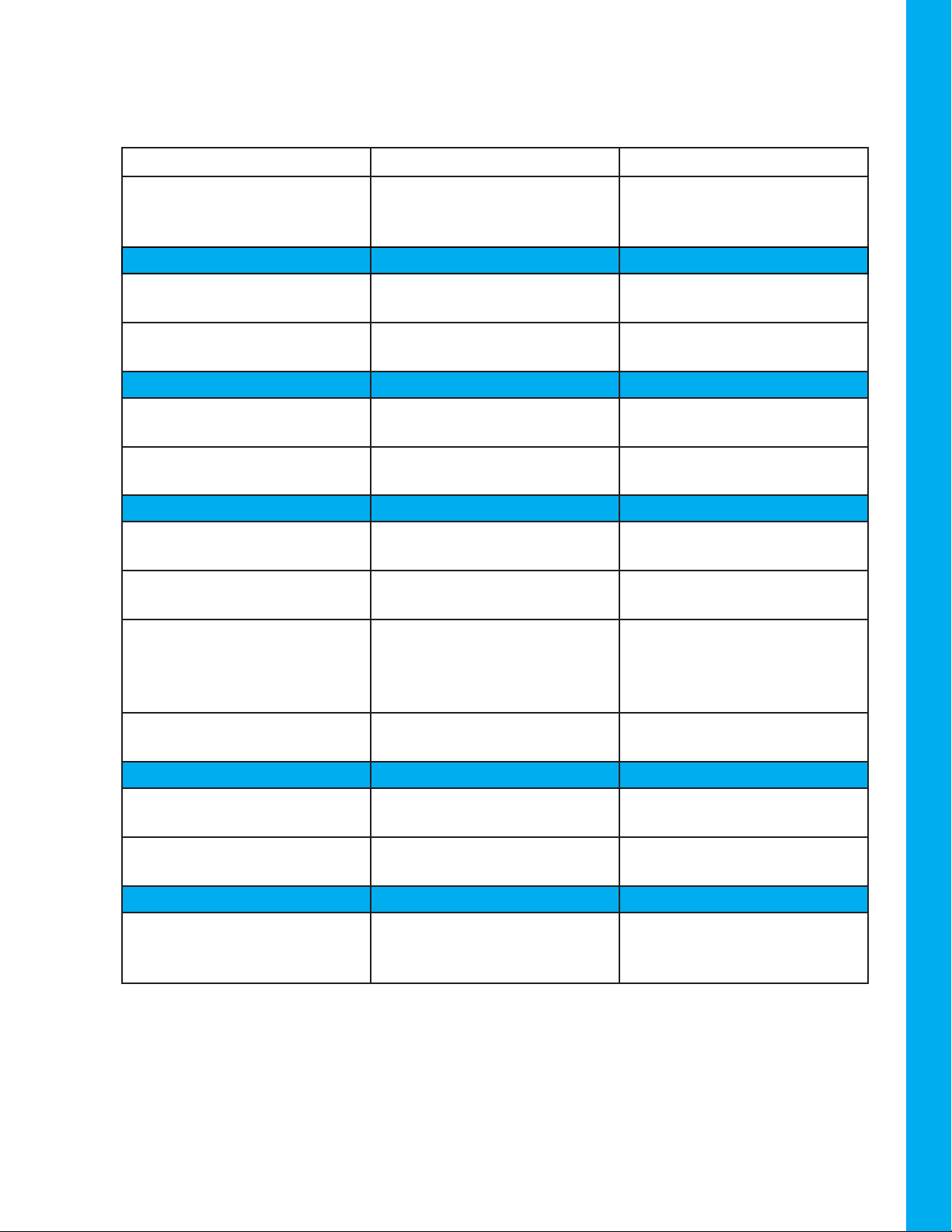
System Possible Cause Solution
Unit doesn’t turn on Unit is not connected to pow-
er source, or is connected to
improper power source
Refer to Input Power Require-
ments, section 4.0, for proper
electrical requirements
Red light on power supply will
not illuminate
Improper outlet voltage Verify power at outlet
Damaged or defective power
supply
Replace power supply
Green light on ozone genera-
tor will not illuminate
Damaged or defective power
supply
Check power supply
operation; replace if necessary
Loose or disconnected inter-
nal wiring
Check internal wiring; remedy
any loose connections
Unit turns on, but no ozone
output
High voltage lead not
connected to CD cell.
Connect frequency driver HV
lead to CD cell
Water has backed up into CD
cell
Clean or replace CD cell.
Cell is plugged with nitric by-
product buildup or particulate
matter
Clean or replace CD cell.
If not installed, install an air
dryer onto ozone generator
air inlet
CD cell not seated in retaining
clips
Re-install CD cell into
retaining clips
Moisture in the inlet and/or
outlet tubing
Improper air preparation Install an air dryer onto ozone
generator air inlet
Yellow discoloration in the
outlet tubing
Nitric byproduct buildup in
CD cell and/or tubing
Clean or replace CD cell and/
or tubing
Water has backed up into the
ozone unit
Failed or missing inline check
valve on ozone output tubing
Clean or replace CD cell.
Replace or install new inline
check valve.
5
6.0 Troubleshooting Guide

7.0 Illustrations
Figure 1. Typical well application w/contact tank and EOG lter
Figure 2. Typical well application w/EOG lter
6

Figure 3. AIM PCS 200 internal diagram
7

8.0 Limited Warranty
Ozotech, Inc., warrants, to the original purchaser, the A.I.M. series ozone generators to be free
from defects in workmanship and material for (12) months from date of purchase. The corona
discharge cell is warrantied against catastrophic electrical failure for (2) years from date of
purchase. All parts, repaired or replacement, will be warranted only for the balance of the
original warranty period. Ozotech, Inc.’s warranty obligation with regard to equipment not of
its own manufacture is limited to the warranty actually extended to the Ozotech, Inc. by its
supplier. Ozotech, Inc. will refund the purchase price, perform repairs or replace equipment, at
the option of Ozotech, Inc.
The warranty shall be null, void, and non-binding upon Ozotech, Inc. if Ozotech, Inc. (or
authorized service center) determines the cause of malfunction or defect to be a result of:
1) Failure to perform proper maintenance as dened and recommended in this manual.
2) Failure to adhere to and provide proper operating conditions, as dened in
this manual, including operation outside of temperature range, operating in wet or
dirty environment, operation outside of manufacturer's specications.
3) Adjustments made by user other than product output ow rate within ranges
specied by manufacturer.
Ozotech, Incorporated assumes no liability for damages incurred by deliberate or incidental
misuse of this product, or damages incurred in transit.
8

9.0 Returns
If the need arises to return your equipment for service, the following procedure must be
followed to ensure accurate and timely processing of repairs.
✓Obtain the serial number, model number and model name of unit to be returned.
✓Contact Ozotech, Inc. and request a Return Material Authorization (RMA) form. Make
sure to give the factory representative an accurate and current shipping address.
✓Provide a description detailing the problem with the unit. Be as specic as possible.
✓After receipt of RMA form, package unit for shipment. Enclose the RMA form with
the unit. Use the original packaging materials if possible. If not possible, please
package the product to ensure against shipping damage.
✓Clearly write the RMA number on the outside of the shipping package.
✓Verify that the address is correct and current.
✓Shipments that are not factory authorized will be refused.
It is recommended that you ship with a reputable and reliable shipping company, and that the
contents of the package are insured. Ozotech, Inc., accepts no responsibility for damage or loss
of equipment in transit.
ALL FREIGHT CHARGES INTO THE FACTORY MUST BE PREPAID. If the repair is covered under
warranty, the factory will pay return shipping charges (surface rates only) to the address listed
on the RMA, within the continental United States.
If the repair is not covered under warranty, the returning party is responsible for payment of
return shipping and handling charges, as well as labor and equipment costs associated with the
repair.
9

Ozotech, Inc. • 1015 South Main Street, Yreka, CA 96097 • Ph. 530.842.4189
ozotech.com
Table of contents
Other Ozotech Oxygen Equipment manuals
Popular Oxygen Equipment manuals by other brands

MedKlinn
MedKlinn O3 HYDRO 5 user manual

Precision Medical
Precision Medical EasyPulse POC PM4150 Series user manual

PURE
PURE CH5000S Product information and user instructions

Teledyne
Teledyne 3160 operating instructions

AirSep
AirSep SeQual Workhorse Series instruction manual

Precision Medical
Precision Medical PM5900 user manual