PAC OS-4 User manual

Pacifi c Accessory Corporation - 1502 S. Santa Fe Street, Santa Ana, CA 92705
10-06-08
The OS-4 is a plug and play interface that allows the replacement of a General Motors GMLAN factory radio. The OS-4 will
maintain operation of the OnStar® system in vehicles with Bose® audio systems, amplifi ed audio systems and also audio
systems without external amplifi ers . The OS-4 has on board switching that allow audio from the OnStar® system to play
through the two front factory speakers. This interface retains all warning chimes, audible turn signal indicators, Bluetooth
and the Vehicle Rear Parking Assist System (if equipped). The factory XM radio tuner can be controlled from the Rear Seat
Entertainment (RSE) Controls. RSE headphone jacks will also remain active and are designed for use with dual zone radios
and the factory installed XM tuner. If the overhead LCD is present the IR headphone system will also be active.
General Motors OnStar®
Interface for GMLAN Vehicles With or
Without Factory Amplifi ed Audio Systems
The Following General Motors Vehicles using the GMLAN Data Bus
Chevy: Express (08) Equinox (07-08) Suburban (07-09) Tahoe (07-09) Avalanche (07-09) Monte Carlo (06-07) Silverado - not classic (07-09) Impala (06-09)
Transverse (09)
GMC: Acadia (07-09) Yukon Denali (07-09) Yukon (07-09) Sierra - not classic (07-09)
Cadillac: DTS (06-09) Escalade - including ESV and EXT (07-09) SRX (07-09)
Buick: Enclave (08-09) Lucerne (06-09)
Hummer: H2 (08-09)
Pontiac: Torrent (07-09)
Saturn: Outlook (07-09) Vue (08-09)
Suzuki: XL-7 (07-08)
1. The OS-4 will retain the use of the factory installed XM receiver. Factory RSE Controls must be present for use of this feature.
2. You may use this interface if the vehicle does not have OnStar® but you need to interface with the Bose® amplifi er
3. This interface will work in amplifi ed or non-amplifi ed audio systems.
4. This interface retains the 5.1 audio system in equipped Cadillac vehicles.
5. Built in Smart Mute Circuitry will play OnStar® through the front speakers and allow the RSE audio jacks to continue playing the audio
source selected by the RSE Controls.
• OnStar® active LED and Ignition on LED.
• New radio will operate with the vehicle RAP (Retained Accessory Power) system.
• Provides +12v RAP circuit, Illumination, Vehicle Speed Sensor (VSS) Output, Parking brake, and Reverse trigger outputs.
• OnStar® Volume control via factory steering wheel audio controls or a push-button switch.
• Safety chime audio level is controlled through the Driver Information Center (DIC).
• RSE Controls will play the aftermarket radios dual zone source or the factory XM tuner if serviced.
• Overhead RSE LCD is usable as well as factory IR headphone system and Rear Auxiliary Input Jacks (use PAC Part # GMRVD).
• Steering wheel radio controls can be retained to control new radio by using the SWI-X, ECL2, JACK or PS.
J1850
J1850
Class 2
Class 2
VPW
VPW
Class 2
Class 2
J1850
J1850
1000
1 1
1 0
111
100100
1
1 0
1
1 0
0
1 1
1010000
1
1 0
1
1 0
1 1
100
1
1 0
0
Arbitration
EOD
EOD
CRC
CRC
1000
1000
1000
1000
1000
1000
1000
1000
1 1
1 1
1 1
1 0
1 0
1 0
1 0
1 0
1 0
111
111
111
111
100100
100100
100100
100100
100100
100100
100100
100100
100100
100100
1
1 0
1 0
1 0
1 0
1 0
1
1 0
1 0
1 0
0
0
0
1 1
1 1
1010000
1010000
1010000
1010000
1010000
1
1 0
1 0
1 0
1
1 0
1 0
1 1
1 1
100
100
1
1
1 0
1 0
0
0
Class 2
Class 2
Class 2
Class 2
Class 2
Class 2
Class 2
Class 2
Class 2
Class 2
Class 2
Class 2
Class 2
Class 2
Class 2
Class 2
J1850
J1850
J1850
J1850
J1850
J1850
J1850
J1850
Notes
Supported Vehicles
Installation
OS-4
OS-GMLAN29
OS-NAV
XM R
XM L
Connect to SWC
Interface. Program
for Version 2.
OS-RADPWRAUDIO
• Aftermarket radio connections are made at the 20-pin OS-RADPWRAUDIO connector.
A detailed description of these wires is on the next page.
• If the vehicle has Rear Seat Audio Controls and the XM tuner is serviced plug the 8 pin
XM Audio output cable into the OS-4. The RCA cables will feed the XM audio into the
aftermarket radios AUX input (if available). The XM RCA cables are not necessary for
Rear Seat Audio but will allow the headunit to play the XM audio through the cabin.
• Factory installed audio options such as Bose, Harman Kardon or Pioneer amplifi ers
will determine the 16-pin OS-GMLAN29 connection. If the vehicle has a factory installed
amplifi er use the Factory Amplifi er Audio location. If a factory installed amplifi er is not
present use the Non-Amplifi ed Factory Audio location.
• The OS-NAV connector has VSS, Reverse and Parking Brake outputs as well as the
OnStar push button volume adjustment input.
• If SWC buttons are present and retained using a radio specifi c SWC interface use the
provided plug. No other connections or splices are necessary.
• The CMX retains all factory warning and safety chimes. If the vehicle chimes when the
radio is removed the CMX is not needed.
• The Mute loop (if not cut) will turn the ACC. output off when an OnStar or Bluetooth call
is made or received. If the aftermarket radio has a mute input cut this loop and connect
the outer brown wire to the mute input. Vehicle Connections
Navigation Connections
SWC Interface
Connections
Upgraded Radio Connections

Pacifi c Accessory Corporation - 1502 S. Santa Fe Street, Santa Ana, CA 92705
10-06-08
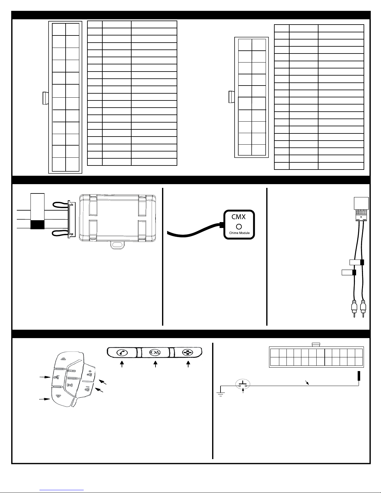
Connecting to and Using OnStar
Connecting the OS-4 to an aftermarket radio
SWC Output Connector
Press and
Hold for
1.5 seconds
to Activate
Onstar Voice
Recognizition or
Bluetooth Phone
Services
Raises and
Lowers Onstar
the Audio
Level While
Onstar is
Active
(7 positions)
Activate
Onstar Voice
Recognizition
Services
Connect to
Onstar
Personal
Calling
Setvices
Onstar
Emergency
Services
Ends Current
Onstar Call
or Rejects
Incoming
Bluetooth or
OnStar Call
• To activate Bluetooth Services (if present) and OnStar Services if Bluetooth is not present press and
hold the Speak SWC button for 1.5 seconds. Pressing the circled phone button on the OnStar touch
pad will only activate OnStar Services.
• Pressing the SWC Vol+ or Vol- during an OnStar/Bluetooth connection will raise and lower the
OnStar or Bluetooth audio level.
• Pressing the down arrow SWC button or circled phone button on the OnStar touch pad during an
OnStar or Bluetooth call will end the current OnStar connection. The down arrow will also reject
incoming OnStar or Bluetooth calls.
• OnStar Personal calling and Emergency services can be activated by the buttons on the mirror.
OnStar Level Control for Vehicles without SWC Buttons
• If SWC buttons are not present a SPST switch can be used to control the
OnStar audio level during an OnStar connection.
• Using the provided Green/White wire, connect the non-terminated end to one
side of a SPST normally open momentary switch (not included).
• The terminated end will go into the OS-NAV connector position X (see picture
above).
• The other side of the SPST switch will be connected ground.
• When OnStar is active pressing the switch will raise the audio level 7 times
before returning to the original level.
12
13
24
Green/White wire
SPST N.O. switch (not included)
Wire insertion side view
(OS-NAV 24-pin connector) VSS
(purple/white)
Parking
Brake
(red/white)
Reverse
(green)
O.S.
Level Switch
(green/white)
1 Green/White OnStar Level Control
2 N.C.
3 N.C.
4 N.C.
5 N.C.
6 N.C.
7 N.C.
8 Purple/White Vehicle Speed Sensor Output
9 N.C.
10 N.C.
11 N.C.
12 N.C.
13 N.C.
14 N.C.
15 N.C.
16 N.C.
17 Green Reverse Light Output
18 Red/White Parking Brake Output
19 N.C.
20-24 N.C.
1 White FL+ Speaker Input
2 Grey FR+ Speaker Input
3 N.C.
4 N.C.
5 Black Ground
6 Yellow Battery
7 Brown Mute Sense Input
8 Purple RR+ Speaker Input
9 Green RL+ Speaker Input
10 Brown Mute Output (-)
11 White/Black FL- Speaker Input
12 Grey/Black FR- Speaker Input
13 Red RAP Output
14 Burgundy Chime+
15 Orange Illumination Output (+)
16 Blue/White Amp On Input
17 White/Green SWC Output
18 Purple/Black RR- Speaker Input
19 Green/Black RL- Speaker Input
20 Black Chime -
2
3
4
5
6
7
8
9
10
11
14
15
16
17
18
19
20
21
22
23
1
12
13
24
OS-NAV
(Wire side view)
OS-RADPWRAUDIO
(Wire side view)
2
3
4
5
6
7
8
9
10
12
13
14
15
16
17
18
19
20
1
11
• The OS-4 provides a SWC output connector attached to the OS-
RADPWRAUDIO harness. For ease of installation, all necessary
connections for a SWI-X, ECL2, JACK, or PS have made for you.
• When using this SWC output connector the radio specifi c SWC interface
must be programmed for version 2 (refer to SWC interface programming
instructions for exact programming sequence).
• Both loops should also remain in tact.
• During steering wheel button assignment programming each button
should be pressed and held for 1 second after the SWC interface LED
goes out with the exception of the Speak button.
• The speak button should be pressed for less than 1 second and
released.
• Pressing the Speak button for longer than 1.5 SEC will activate OnStar.
From SWC
Buttons
From OnStar Touch Pad
Connect to SWC
Interface. Program
for Version 2.
Connect to Radio
Specific SWC
Interface
Using the CMX
• The provided CMX will play all safety/warning
chimes and turn signal/hazard light tones in
vehicles that do not play these chimes/tones when
the factory installed radio is removed.
• When the radio is removed - if factory chimes still
play the CMX is not needed. The CMX cable (2-
pin connector attached to the OS-RADPWRAUDIO
interface harness) should be tied up as it is not
used for any other connections.
• To adjust the level of the warning and safety
chimes refer to the vehicles owner manual for
Driver Information Center (DIC) settings. Not all
vehicles have a DIC. If the DIC is not available the
chime level is not adjustable.
Center and Sub Connections
Center
SUB
• Some Cadillac vehicles are
equipped with a Dolby Surround
Sound Amplifi ed Audio System. The
amplifi ers 5.1 mode is enabled when
the RSE system is off and OnStar is
not active. If the aftermarket radio
has a dedicated center channel
and or sub output connect it to the
provided cable as labeled. Refer to
the aftermarket radios owner manual
for surround sound settings and
adjustments.
• If the aftermarket radio to be
installed does not have a dedicated
center channel or sub output do not
use this cable. To ensure best sound
performance channel summing is
not recommended. Use this cable
according to the outputs that are
available.
• This cable can also be used for
factory reverse camera retention if
available and if center channel and
or sub connections are not needed
(see Notes section of this manual).

Pacifi c Accessory Corporation - 1502 S. Santa Fe Street, Santa Ana, CA 92705
10-06-08
1. Turn ignition on. The red ignition LED inside the interface will turn on and the +12v accessory wire will turn on.
2. Turn on the radio and check balancing and fading. Note: The RPO code UQA (standard digital Bose® amplifi er) will not fade as the
rear outputs of aftermarket radio do not adjust the amplifi er.
3. Pressing the OnStar® button will turn off the rear speakers and allow the OnStar® audio to be heard in the two front speakers. The
OnStar® active red LED will also turn on. When OnStar® disconnects, the radio will un-mute or turn back on and the OnStar® LED will
turn off.
4. Turn off vehicle and remove key. RAP will be active and keep the radio on for 10 minutes or until the drivers door is opened.
5. The red ignition On LED and radio will turn off when RAP turns off or the drivers door is opened.
6. Pressing the Mute/OnStar® button on the steering wheel for 1.5 seconds will also activate Onstar®.
DISCLAIMER: Under no circumstances shall the manufacturer or the distributors of the OS-4 parts be held liable for consequential damages sustained
in connection with the OS-4. The manufacture and it’s distributors will not, nor will they authorize any representative or any other individual to
assume obligation or liability in relation to the OS-4 other than its replacement.
OnStar® is a registered trademark of OnStar® Corporation.
Bose® is a registered trademark of Bose®
Installation Notes
1. When the interface is connected to the vehicle for the fi rst time the car must be started so all vehicle features are recognized by the interface.
2. DO NOT cut the Brown loop on the SWC interface connector. Program the radio specifi c SWC Interface for version #2.
3. When the Rear Seat Audio jacks are activated in any vehicle OTHER than the Cadillac Escalade or a UQA amplifi ed vehicle the rear speakers will mute.
4. The headphone jacks will play the rear zone source selected by the head unit (refer to the new radios instruction manual for details on this feature if
equipped). Maximize the rear zone volume level (this will reduce unwanted noise). During an OnStar call the front speakers play OnStar, the rear speakers are
muted and the headphones will continue to play the rear zone audio source.
5. Using the Center and Sub cable for factory reverse camera retention.
Using the Rear Seat Audio Controls
Testing and Verifying Operation
Radio
Turns the
Rear Seat
Controls On
or Off
Change between
Factory XM tuner
and Dual Zone
Radio Source
Controls the
Radio as
Programmed
by the SWC
interface (Mapped
to the Arrow
and Bar Button)
Controls the
Radio as
Programmed
by the SWC
interface (Mapped
to the Arrow
Down Button)
Controls the
Radio as
Programmed
by the SWC
interface (Mapped
to the Arrow
Up Button)
XM 16
Turns the
Rear Seat
Controls On
or Off
Change between
Factory XM tuner
and Dual Zone
Radio Source
Has No
Function
Seek to the
Next
Factory XM
Tuner Station
Seek to the
Previous
Factory XM
Tuner Station
Using the Radios Dual Zone Source Using the Factory XM Radio Tuner
• Press the power button to turn the RSE Controls on. When Radio is displayed on the RSE
Controls, the aftermarket radios rear speaker output will be heard through the headphone
jacks. Putting the aftermarket radio into dual zone mode should change the output level
of the rear speakers to a fi xed level. This allows precise user adjustment from the level
knobs on the RSE Controls (refer to aftermarket radio owners manual for model specifi c
dual zone operation).
• The seek arrows and PROG button will control the radio as programmed by the SWC
interface. These buttons are mapped to the SWC buttons as stated above.
• Pressing the SRCE button will toggle between the Factory XM tuner and the Radio as the
RSE source. Pressing the power button will turn the RSE Controls off as well as turning
the key off. The seek arrows and PROG button will continue to operate as stated (with the
exception of SRCE which has no function) when the Rear Seat Controls are turned off.
• Press the power button to turn the RSE Controls on. If Radio is displayed press the
SRCE button to select factory XM tuner mode. When XM followed by the channel number
is displayed factory XM tuner audio will be heard through the headphone jacks.
• The Seek arrows will control the factory XM radio tuner and select the desired station.
• The PROG button has no function.
• Pressing the SRCE button will toggle between the Factory XM tuner and Radio as
the RSE source. Pressing the power button or turning the key off will turn off the RSE
Controls.
• The factory XM tuner must remain serviced to take advantage of this feature. Visit www.
xmradio.com for a complete up-to-date channel listing and service options.
OnStar Level Control for Vehicles without SWC Buttons
• With the supplied brown connector NOT attached to the vehicles brown radio connector: lift the upper and
lower locking tabs near the wire insertion part of the supplied brown connector which houses the center and
sub RCA cables.
• Depress the silver exposed locking tabs on which ever RCA connector (center or sub) is not being used during
this installation.
• After removing both shield (black) and center conductor (red or white) pins - re-insert as follows (see image
aside).
• Pin 6 is the camera+ signal and Pin 7 is the camera- signal. After inserting the pins clasp the locking tab back
down to lock the moved pins into place.
• Fit the modifi ed brown connector into the vehicles brown connector and plug the moved RCA cable into the
aftermarket radios camera input (mark this RCA cable for future reference).
• Use the supplied reverse output wire (green wire in OS-NAV connector) for automatic switching when the
vehicle is put into reverse.
12
3
45
6
7
8
1112 10 9
9
16
Center and Sub
Brown Connector (supplied
with interface)
3: Center +
4: Sub +
6: Camera +
7: Camera -
11: Center -
12: Sub -
10
11
1213
14
15
Wire side view
X
XX
X
X
X
6. DTS, Equinox, Torrent and Vue Installation Notes:
If the vehicle is equipped with a factory amplifi er other than a Bose amplifi er and OnStar audio is not heard
during operation the Black/White wire located in the OS-GMLAN29 harness needs to be cut in half and insolated
at both ends (c2 vehicle (16pin) connector pin 8) .
Table of contents
Other PAC Automobile Accessories manuals
Popular Automobile Accessories manuals by other brands

Scosche
Scosche TAQ04 manual

Webasto
Webasto Telestart T70 installation instructions

Toyota
Toyota 2005 4Runner Navi_U owner's guide

Curt Group
Curt Group Liverne 401801 installation manual

VERIGA
VERIGA MAXI GRIP user manual

Lippert Components
Lippert Components COACH STEP Installation, operation and service manual