PAC RP4.2-TY11 User manual

Radio Replacement and
Steering Wheel Control Interface
for Toyota / Lexus / Scion Vehicles
RP4.2-TY11
Introduction & Features
Important Notes
The RP4.2-TY11 interface allows the replacement of a factory radio in select Toyota/Lexus/Scion vehicles and will retain
factory features such as steering wheel controls (SWC) and the factory audio amplier. This interface also allows you to
program two radio functions to each SWC button by using short press long press dual command functionality, and also
provides outputs such as: vehicle speed signal (VSS), illumination, reverse trigger and parking brake.
1. These instructions only apply to R.2.1.1.43 or later revisions. The revision info can be found on a small white sticker on the
interface and packaging.
2. Connection of the White / Red and White / Black wires is not always necessary. Use of these wires will be dependent on whether
or not the aftermarket radio requires specific connections, and whether the vehicle provides these outputs at the radio. See the
“Installation Steps” section starting on page 3 for additional information.
3. Adjustment of the vehicle settings through the original radio’s vehicle settings menu will be disabled after installation of the new
radio. It is advised to make sure all settings are as you desire prior to removal of the original radio.
4. The RP4.2-TY11 does not retain Rear Seat Entertainment.
5. After installation, if you do not initially hear any audio, you may need to cycle the ignition again to initialize the factory amplifier.
6. Speaker fading on factory amplified systems is only supported with the “amplified output” connection of the RP4.2-TY11.
7. When using real time fade, if the fader setting is biased more to the front or rear, as the radio turns on the sound may begin at
the default setting and then quickly transition to your custom setting.
8. Aftermarket radio features such as High Pass Filters (crossovers), DSP or “Network Mode” will interfere with proper fader
function. In order for the RP4.2-TY11’s fader function to work, the audio from the aftermarket radio’s output must match so it can
compare the front and rear audio levels and determine the proper fader setting for the factory amplifier.
9. The USB-TY1 or USB-TY2 must be purchased in order to retain the factory USB port.
10. The CAM-TY11 or CAM-TY12 must be purchased in order to retain the factory reverse camera.
Module Layout
Module Status LED
USB Status LED
Interface Connector 1
Expansion Port
Interface Connector 2
Amplied Audio Output
Non-Amplied Audio Output
Programming Button
USB Port
Radio Select DIP switches
Interface Connector 4
Amplied Audio Output Level Adjustment

Radio Replacement and
Steering Wheel Control Interface
for Toyota / Lexus / Scion Vehicles
RP4.2-TY11
Interface Connectors
Plug Interface Connectors 1, 2 and 4 into the appropriate port on the RP4.2-TY11 interface (using the diagram on page 1 or
the label on the bottom of the RP4.2-TY11 interface). The Connector 3 connection will be dependent upon whether or not the
vehicle has a factory amplied system. Connect to the appropriate port on the RP4.2-TY11.
Vehicle Connectors
Depending on the application, the RP4.2-TY11 will need 2 or 3 of the 5 vehicle connectors. The additional connectors will be
left unused on the harness. Any additional radio harnesses in the vehicle that do not plug into one of the vehicle connectors
shown above, will not be used. Below you will nd the typical combinations needed for most vehicles.
Combination 1
Typical 2004 to 2013 NON-AMPLIFIED
Vehicle Connector 3 Vehicle Connector 4 Vehicle Connector 5
Combination 2
Typical 2004 to 2013 AMPLIFIED
Vehicle Connector 1 Vehicle Connector 3
Combination 3
Typical 2014 to 2017 AMPLIFIED AND NON-AMPLIFIED
Vehicle Connector 2 Vehicle Connector 4 Vehicle Connector 5
Interface Connector 1 Interface Connector 2 Interface Connector 4
Interface Connector 3
Vehicle Connector 1 Vehicle Connector 2 Vehicle Connector 3 Vehicle Connector 4 Vehicle Connector 5

Radio Replacement and
Steering Wheel Control Interface
for Toyota / Lexus / Scion Vehicles
RP4.2-TY11
Installation Steps
Other = Advent, BOYO, Dual, Lightning Audio, Rockford Fosgate, Visteon
Other =
Advent, BOYO, Dual, Lightning Audio, Rockford Fosgate, Visteon
Alpine JVC Kenwood Clarion /
Nakamichi
Pioneer /
Other* Sony Fusion
1 2 1 & 2 3 1, 2, & 3 4 1 & 4
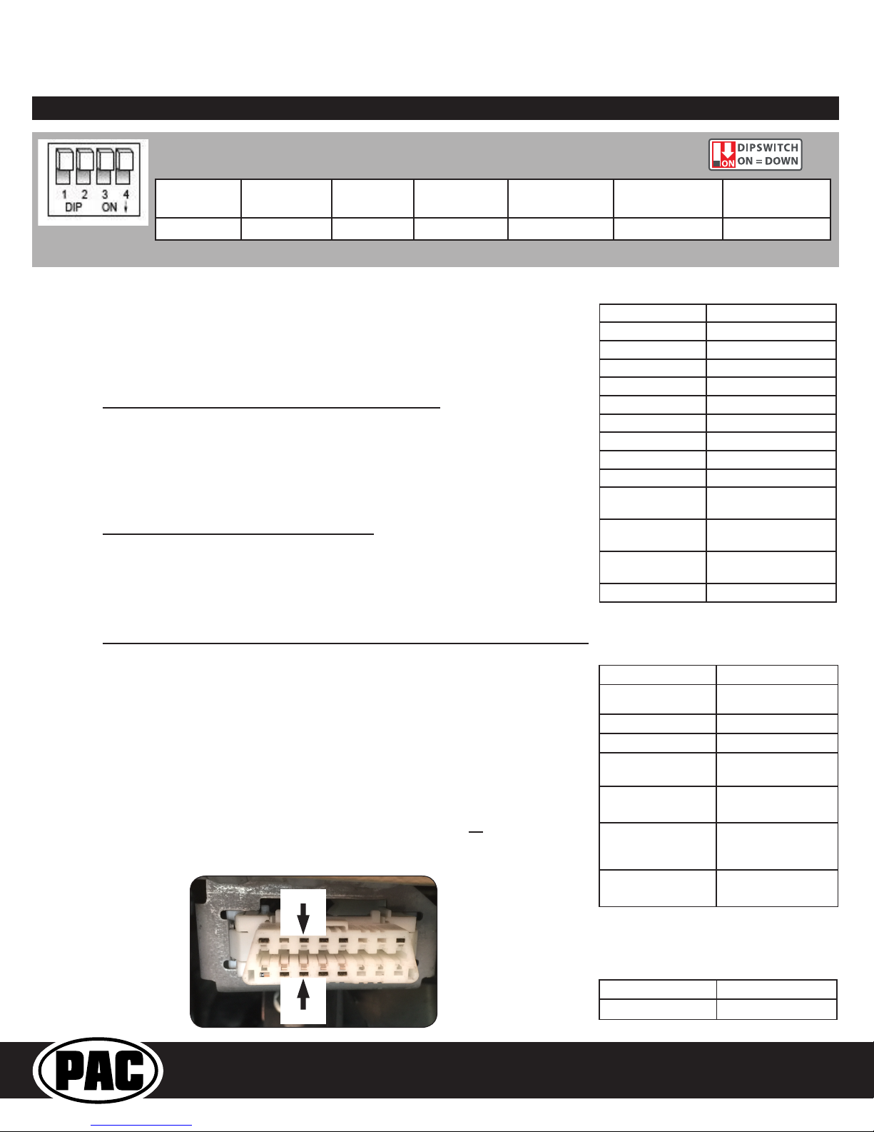
Set DIP switches that correspond with your radio to the ON position.
Set all other DIP switches to the OFF position.
* Other - Advent, BOYO, Dual, Jensen, Lightning Audio, Rockford Fosgate, Visteon
Purple Rear R + input
Purple / Black Rear R - input
Green Rear L + input
Green / Black Rear L - input
Gray Front R + input
Gray / Black Front R - input
White Front L + input
White / Black Front L - input
Blue / Yellow SWC Output
3.5 mm Jack SWC Output
Pink Vehicle Speed
Sense Output
Light Green Parking Brake
Output
Violet / White Reverse Signal
Output
Orange / White Illumination Output
Blue / White Amp Turn On Input
1. Set the Radio Select DIP switches according to the radio you are installing.
2. Wire the aftermarket radio harness per the tables to the right and the information
below. If the aftermarket radio does not require connections for Vehicle Speed
Sense, Parking Brake, or Reverse Signal, proceed to step “3”.
a. If the vehicle does not use the 28 pin connector (Vehicle Connector 2), proceed
to step “III” below. There are three different methods for obtaining the analog
navigation outputs from the interface:
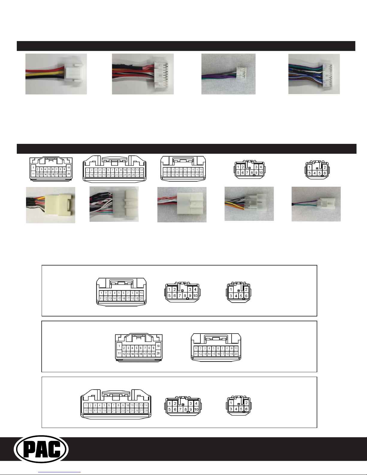
I. Vehicles that have the analog signals at the radio: Plug the 28 pin con-
nector (Vehicle Connector 2) from the RP4.2-TY11 into the vehicle harness.
Find the Pink (pin 17), Light Green (pin 15) and Purple / White (pin 2) wires
in the RP4.2-TY11 harness and check for wires populating these positions
on the factory side of the connector. If the wires are present, you can use
the analog navigation outputs coming from the Vehicle Connector in the PAC
harness.
II. Vehicles that have CAN data at the radio: Plug the 28 pin connector (Vehicle
Connector 2) from the RP4.2-TY11 into the vehicle harness. Find the White
/ Red (pin 9) and White / Black (pin 10) wires in the RP4.2-TY11 harness and
check for wires populating these positions on the factory side of the connector.
If the wires are present, you can use the “nav wires” coming from Vehicle
Connector 2 in the PAC harness.
III. Vehicles that do not have the CAN data or the analog wires at the radio:
Connect the long White / Red HS-CAN+ wire to pin 6 and the long White /
Black HS-CAN- wire to pin 14 in the OBDII connector (Fig.1). This will allow for
use of the “nav wires” coming from Interface Connector 4 in the PAC harness.
3. Wire the Yellow, Red, and Black wires from the harness labeled “Connect to Aftermarket
Radio” to the wires on the aftermarket radio harness.
4. Wire the speaker wires from Interface Connector 4 to the speaker wires on the
aftermarket radio harness.
5. Wire the Blue / White wire from Interface Connector 4 to the amp turn on lead of your
aftermarket radio. Insulate the unused wires and ignore the remaining Brown Loop
(not needed).
6. Depending on the aftermarket radio, either the Blue / Yellow wire or the 3.5 mm
Jack (not both) SWC Outputs will be used.
White / Red HS CAN + Input
White / Black HS CAN - Input
Yellow 12v+
Red Accessory Output
(10 amp)
Black Ground
Pink Vehicle Speed
Sense Output
Light Green
Parking Brake
Outpu
t
Violet / White Reverse Signal
Output
Aftermarket Radio Wiring Table
Wires from Interface
Connector 4
Wires Labeled “Connect To
Aftermarket Radio”
CAN Input Wires
7. Once all connections have been made, plug the interface into the vehicle.
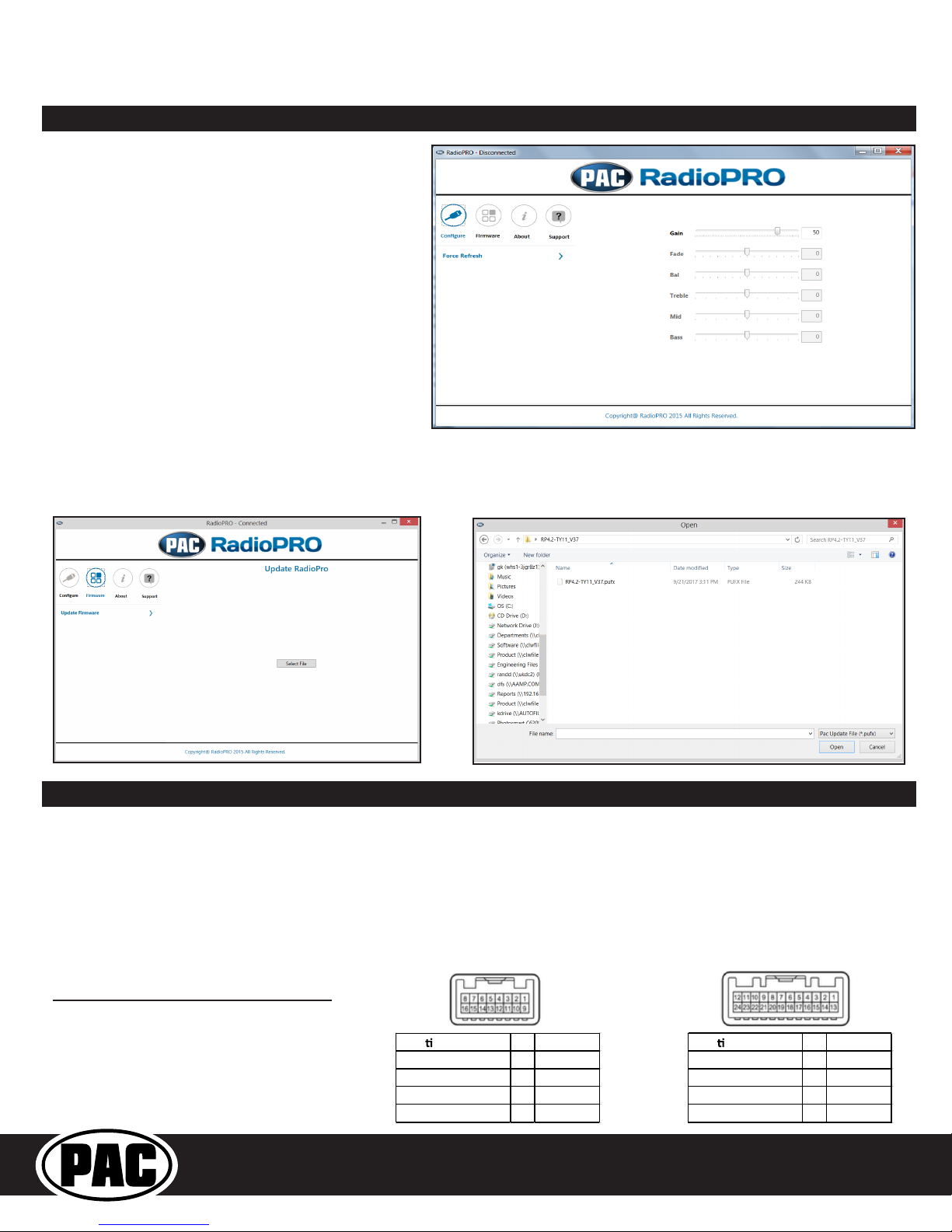
8. Turn the ignition on and set the gain on the side of the interface to the desired level.
See “Testing & Verication” section on page 6 for further details on how to set the
gain. If the radio does not turn on and the LED on the interface is solid orange, check
the DIP switches on the side of the interface to make sure they are not all in the on
position.
9. If you wish to reassign functions to the SWC, or utilize short press long press dual
command functionality, follow the programming instructions on the following page.

Radio Replacement and
Steering Wheel Control Interface
for Toyota / Lexus / Scion Vehicles
RP4.2-TY11
Default Steering Wheel Control Programming
IMPORTANT! The interface comes pre-programmed for all of the vehicles factory SWC functions and does not require
programming unless you wish to re-assign the SWC functions, utilize short press long press dual command functionality, or
assign the programmable 12v output to a SWC button. The SWC can always be restored to default settings by pressing and
releasing the program button on the side of the interface once and waiting 7 seconds for the LED to ash 3 times.
Optional Steering Wheel Control Programming
If you wish to re-assign the SWC functions, utilize short press long press dual command functionality, the interface must be
programmed in the specic order shown in the chart on page 5. If you come across a function in the chart that your steering
wheel does not have, or you do not want to program, press and release the programming button on the side of the interface to
skip that function. The LED will ash off and on conrming that you have successfully skipped that function and are ready to
proceed to the next one.
Short Press Long Press Dual Command Functionality
This feature allows you to assign two aftermarket radio functions to each of the vehicles SWC buttons. It can be used with as
many of the buttons as the user likes or none at all. When this functionality is implemented, quickly pressing and releasing a
SWC button will initiate the short press command while pressing and holding a SWC button for longer than two seconds will
initiate the long press command. Please note that no long press commands are programmed by default. If you wish to assign
dual command functionality to the SWC please follow the programming steps below.
Steering Wheel Controls
Alpine JVC Kenwood Clarion Pioneer Sony Fusion
Volume + Volume + Volume + Volume + Volume + Volume + Volume + Volume +
Volume - Volume - Volume - Volume - Volume - Volume - Volume - Volume -
Mode Source Source Source Source Source Source Source
Back Band Att Play Band Band Band N/P
Voice VR Mute Mute VR VR VR Mute
Answer Receive Receive Off Hook Send Answer Answer Power
End End Reject On Hook End End Reject/Source N/P
Enter Power Power Preset Up N/P Mute N/P Power
Arrow Up Track Up Track Up Track Up Track Up Track Up Track Up Track Up
Arrow Down Track Down Track Down Track Down Track Down Track Down Track Down Track Down
Arrow Left Preset Down Disc Down Disc Down N/P Preset Down Preset Down N/P
Arrow Right Preset Up Disc Up Disc Up N/P Preset Up Preset Up N/P
Default SWC Button Assignments

Radio Replacement and
Steering Wheel Control Interface
for Toyota / Lexus / Scion Vehicles
RP4.2-TY11
Steering Wheel Controls (cont.)
Alpine JVC Kenwood Clarion Other * Pioneer Sony Fusion
1 Volume + Volume + Volume + Volume + Volume + Volume + Volume + Volume +
2 Volume - Volume - Volume - Volume - Volume - Volume - Volume - Volume -
3 Mute Mute Mute Mute Mute Mute Mute Mute
4 Preset + Source Source Source Preset + Preset + Preset + Source
5 Preset - Track + Play Search + Preset - Preset - Preset - Track +
6 Source Track - Track + Search - Source Source Source / End Call Track -
7 Track + Band / Disc + Track - Band Track + Track + Track + Audio
8 Track - Preset / Disc - Disc / FM + Send / End Track - Track - Track - Power
9 Power Select Disc / AM - Send Band Band Band
10 Enter / Play Attenuation Answer End Answer ** Phone Menu Power / End Call
11 Band / Program Phone Receive Voice Dial VR End ** Answer Call Voice Dial / Answer / End Call
12 Receive Phone Reject On Hook PTT ** End Call VR (Android Auto & Car Play)
Answer / End Call***
13 End Voice Dial Off Hook VR
14 VR Power Mute
15 Preset +
* Advent, Boyo, Dual, Lightning Audio, Jensen, Rockford Fosgate & Visteon ** Jensen & Advent ONLY ***
XAV-AX100 Only
Optional Programming Order
5. If you come across a function in the chart that your steering wheel does not have, or you do not want to program, press and
release the program button on the side of the interface to skip that function.
6. Once programming is completed, wait seven seconds. The LED will ash three times indicating end of programming.
7. Test the interface for proper functionality. Whenever a SWC is pressed the LED on the interface should blink. If any function
does not work, repeat the programming steps.
SWC Re-Calibration Procedure
1. Turn the key to the ignition position.
2. Press and hold the programming button until the LED begins blinking amber.
When the LED begins blinking, release the programming button. The LED will
light solid amber.
3. Within 7 seconds, press and hold the button that is to be learned on the steering
wheel. The LED will turn off when the button is pressed and begin blinking when
the value has been learned. Once the LED begins blinking, release the button.
Please Note: the buttons must be calibrated in the order shown in the chart.
If you press the wrong button the LED will not respond at all.
4. If you need to program more buttons, repeat step 3 for each additional audio
function on the steering wheel.
5. If you come across a function in the chart that your steering wheel does not
have, press and release the program button on the side of the interface to skip
that function.
6. Once programming is completed, wait seven seconds. The LED will ash
indicating end of programming.
7. Test the interface for proper functionality. Whenever a SWC is pressed the
LED on the interface should blink. If any function does not work, repeat the
programming steps.
Re‐CalibrationProgrammingOrde
r
VolumeUp
VolumeDown
SeekUp
SeekDown
Mode
Voice
PhoneAnswer
PhoneHangUp
Enter
Back
ArrowRight
ArrowLeft
After you have re-calibrated the SWC buttons, the default SWC button assignments will be the same as what is listed in the
chart on page 4. If you wish to re-assign button functions you must also go through the programming listed above (Optional
SWC Programing Procedure).
Optional SWC Programming Procedure
1. Turn the key to the ignition position.
2. Press and release programming button on the side of the interface. The Status LED will turn green.
3. Within 7 seconds, press the button that is to be learned on the steering wheel. The LED will turn red when the button is pressed.
At this point you have two options:
A. For short press functionality: Release the button within 1.5 seconds. The LED will turn back on.
B. For long press functionality: Hold the button until the LED starts blinking. Release the button and the LED will
go back to solid.
4. If you need to program more buttons, repeat step 3 for each additional audio function on the steering wheel.
Other manuals for RP4.2-TY11
1
This manual suits for next models
1
Table of contents
Other PAC Automobile Accessories manuals
Popular Automobile Accessories manuals by other brands

ULTIMATE SPEED
ULTIMATE SPEED 279746 Assembly and Safety Advice

SSV Works
SSV Works DF-F65 manual

ULTIMATE SPEED
ULTIMATE SPEED CARBON Assembly and Safety Advice

Witter
Witter F174 Fitting instructions

WeatherTech
WeatherTech No-Drill installation instructions

TAUBENREUTHER
TAUBENREUTHER 1-336050 Installation instruction