PAC RadioPRO4 User manual

RP4-NI11
Radio Replacement & Steering Wheel Control Interface
for Nissan Vehicles
Pacic Accessory Corporation®| Ph. 866-931-8021 | [email protected]
©2016 Pacic Accessory Corporation
www.pac-audio.com
Rev. 011116
Pacific Accessory Corporation
Introduction & Features
Important Notes
Wiring Connection Chart
Illustration / Schematic
1. The radio select rotary switch on the side of the interface must be adjusted to the proper radio setting before plugging the
interface into the vehicle (see next page for setting chart).
2. The interface comes pre-programmed for all of the vehicles factory SWC functions and does not require programming unless
you wish to re-assign the SWC functions or utilize short press long press dual command functionality. The SWC can always
be restored to default settings by pressing and releasing the program button on the side of the interface once and waiting 7
seconds for the LED to ash 4 times.
3. Does not retain 360 camera system
4. In some 2014+ Nissan Rogues, it may be necessary to nd an alternate accesory 12v+ wire If the interface and aftermarket
radio are not powering up. Please see Appendix A on page 4 to nd an alternate accessory 12v+ wire.
Vehicle Connector SWC Connector
SWC Connection
See above chart for
different radio type
connections
x4
Acc On/
Programming
LED
Programming
Button
Wiring SWC Connection
Yellow Battery +12v
Black Ground
Red Accessory 12v+
Purple / White Vehicle Speed
Output
Blue / White Amp Turn On Input
Orange / White Illumination Output
(+)
Green *Reverse Output (+)
White Front L + input
White / Black Front L - input
Grey Front R + input
Grey / Black Front R - input
Green Rear L + input
Green / Black Rear L - input
Purple Rear R + input
Purple / Black Rear R - input
Yellow RCA *Reverse Camera
Output
Blu/Yel Kenwwod, Newer
JVC
3.5mm Jack Alpine, JVC,
Clarion, Fusion,
Pioneer, Sony,
Boyo, Dual,
Lightning Audio,
Visteon or Advent
The RP4-NI11 interface allows the replacement of a factory radio in select Nissan vehicles with MSCAN databus radios.
Using this interface will retain factory features such as steering wheel controls (SWC), reverse camera and the factory
amplier when the original radio is removed. Use of this interface also allows you to program two radio functions to each
SWC button by using short press long press dual command functionality. The RP4-NI11 also provides outputs such as
vehicle speed sensor (VSS), illumination and *reverse trigger.
* Only available in vehicles
equipped with a factory reverse
camera.
Cut for Non-Bose systems
Aftermarket Radio Connections
See above chart for wire color
description.

RP4-NI11
Radio Replacement & Steering Wheel Control Interface
for Nissan Vehicles
Pacic Accessory Corporation®| Ph. 866-931-8021 | [email protected]
©2016 Pacic Accessory Corporation
www.pac-audio.com
Pacific Accessory Corporation
Rev. 011116
Default Steering Wheel Control Programming
IMPORTANT! The interface comes pre-programmed for all of the vehicles factory SWC functions and does not require programming
unless you wish to re-assign the SWC functions or utilize short press long press dual command functionality. The SWC can always
be restored to default settings by pressing and releasing the program button on the side of the interface once and waiting 7
seconds for the LED to ash 4 times.
Installation Steps
Default SWC Button Assignments
Alpine JVC Kenwood Clarion Pionee
r
Sony Fusion
V
olume + Volume + Volume + Volume + Volume + Volume + Volume + Volume +
V
olume - Volume - Volume - Volume - Volume - Volume - Volume - Volume -
Source Source Source Source Source Source Source Source
Track + Track + Track + Track + Search + Track + Track + Track +
Track - Track - Track - Track - Search - Track - Track - Track -
Ente
r
Play Power Disc Up Band Preset Up Preset Up Power
Phone Answe
r
Receive Receive Answer Send Answer Call Answer/End Audio
Phone End End Reject Voice End End Reject/Source Mute
1. The radio select rotary switch on the side of the interface must be adjusted to the proper radio setting before plugging the interface
into the vehicle.
2. Make all connections as described in the chart on page 1. If there is a Bose® Audio system present: Connect the RCA inputs to the
aftermarket radios pre-amp output. The audio level will vary depending on the new radios pre-amp output voltage (2-4 volts is recommended).
If there is not a Bose® Audio system present: Cut the RCA inputs off and connect the aftermarket radios speaker outputs to the remaining
wire according to the chart on page 1.
3. Base model vehicles may not have a factory ground wire. In these vehicles you will have to manually ground the aftermarket radio and RP4
module.
4. If the vehicle is equipped with a reverse camera and the aftermarket radio has a reverse camera input, connect the yellow RCA plug to the
aftermarket radios reverse camera input.
5. Connect the SWC wire according to the chart on page 1 (aftermarket radio MUST support a wired remote input).
6. If you wish to reassign functions to the SWC follow the programming instructions on the next page.
IMPORTANT! In 2014-2015 vehicles, if you wish to retain the reverse camera in vehicles equipped with factory navigation and
a BOSE system you must solder a video RCA cable into the factory wires at the ITS module. The ITS module can be found by
removing the plastic panel in the passenger footwell that is connected to the center console (Fig. 1). The connector in which you
will nd the video wires is shown in Fig. 2 . Finally you must connect a video RCA cable into the two wires as shown in Fig. 3 (Wire
colors are normally Gray (-) and Black (+) but may vary by vehicle ). Once connected, run this RCA to the aftermarket head unit
and connect to the reverse camera input.
1
2
3
4
5
6
7
8
9
0
Alpine JVC Kenwood Clarion Pioneer/Other Sony Fusion
1 2 3 4 7 8 9
Other = Advent, BOYO, Dual, Lightning Audio, Rockford Fosgate, Visteon
SET RADIO SELECT SWITCH
Fig 1 Fig 2 Fig 3
ITS Module
This Plug Video -
Video +

RP4-NI11
Radio Replacement & Steering Wheel Control Interface
for Nissan Vehicles
Pacic Accessory Corporation®| Ph. 866-931-8021 | [email protected]
©2016 Pacic Accessory Corporation
www.pac-audio.com
Rev. 011116
Pacific Accessory Corporation
Optional Steering Wheel Control Programming
1. Turn the key to the ignition position.
2. Press and release programming button on the side of the interface.
3. Within 7 seconds, press the button that is to be learned on the steering wheel. The LED will turn off when the button is pressed.
At this point you have two options:
A. For short press functionality: Release the button within 1.5 seconds. The LED will turn back on.
B. For long press functionality: Hold the button until the LED starts blinking. Release the button and the LED will
go back to solid.
4. If you need to program more buttons, repeat step 3 for each additional audio function on the steering wheel.
5. If you come across a function in the chart that your steering wheel does not have, or you do not want to program, press and
release the program button on the side of the interface to skip that function.
6. Once programming is completed, wait seven seconds. The LED will ash three times indicating end of programming.
7. Test the interface for proper functionality. Whenever a SWC is pressed the LED on the interface should blink. If any function
does not work, repeat the programming steps
If you wish to re-assign the SWC functions or utilize short press long press dual command functionality, the interface must be
programmed in the specic order shown on the chart below. If you come across a function in the chart that your steering wheel
does not have, or you do not want to program, press and release the program button on the side of the interface to skip that
function. The LED will ash off and on conrming that you have successfully skipped that function and are ready to proceed to
the next one.
Alpine JVC Kenwood Clarion Other* Pioneer Sony Fusion
1 Volume + Volume + Volume + Volume + Volume + Volume + Volume + Volume +
2 Volume - Volume - Volume - Volume - Volume - Volume - Volume - Volume -
3 Mute Mute Mute Mute Mute Mute Mute Mute
4 Preset + Source Source Source Preset + Preset + Preset + Source
5 Preset - Track + Play Search + Preset - Preset - Preset - Track +
6 Source Track - Track + Search - Source Source Source Track -
7 Track + Band/Disc + Track - Band Track + Track + Track + Audio
8 Track - Preset/Disc - Disc/FM + Send/End Track - Track - Track - Power
9 Power Select Disc/AM - Send Band Band Band
10 Enter/Play Attenuation Answer End N/A Phone Menu
Reject Call/Source
(Bluetooth equipped
radios only)
11 Band/Program Phone Receive Voice Dial Answer Call Answer/End Call
12 Receive Phone Reject On Hook End Call
13 End Voice Dial Off Hook VR
14 VR Power Mute (Multimedia
units only)
15 Preset +
*Other = Advent, Boyo, Dual, Lightning Audio, Rockford Fosgate, & Visteon
Optional Programming Order
1
2
3
4
5
6
7
8
9
0
Alpine JVC Kenwood Clarion Pioneer/Other Sony Fusion
1 2 3 4 7 8 9
Other = Advent, BOYO, Dual, Lightning Audio, Rockford Fosgate, Visteon
SET RADIO SELECT SWITCH

RP4-NI11
Radio Replacement & Steering Wheel Control Interface
for Nissan Vehicles
Pacic Accessory Corporation®| Ph. 866-931-8021 | [email protected]
©2016 Pacic Accessory Corporation
www.pac-audio.com
Pacific Accessory Corporation
Rev. 011116
Product Updates (Firmware)
The RP4-NI11 can be updated with new rmware as it becomes available using the PAC-UP interface updater (sold seperatly).
Please visit www.pac-audio.com/rmware for available updates.
Testing & Verication
1. Turn the ignition on. The LED on the interface will turn on & the +12v accessory wire will turn on.
2. Turn on the radio & check balance & fade.
3. Verify that all SWC are functioning properly.
4. The LED & radio will turn off when the key is turned off
Appendix A
When installing the RP4-NI11 into a 2014+ Nissan Rogue it may be necessary to make a hardwired connection for accessory
power. This is necessary due to these vehicles having a different location for the 12v accessory wire. Please follow the procedure
outlined below to make the proper connection.
1. Connect the main 20-pin and 24-pin harnesses as outlined in the instruction manual included with the interface.
2. Locate the light green accessory wire in the 24-pin Nissan factory harness (Fig. 1). This wire will need to be jumped to the red wire located in
pin 16 of the 20-pin RP4 harness (Fig 2).
Illustration / Schematic
RP4-NI11
Connector
Fig. 1
24-Pin Vehicle
Connector
Fig. 2
All connectors are viewed from wire side
Factory ACC Wire RP4 ACC Wire

RP4-NI11
Finding an Accesory 12v+
in 2014+ Nissan Rogue With a Navigation radio
Pacic Accessory Corporation® | Santa Ana, California 92705 | Ph. 866-931-8021 | [email protected]
©2013 Pacic Accessory Corporation
www.pac-audio.com
Rev. 011116
Pacific Accessory Corporation
Page 1 Page 1
Tech Bulletin
Important Notes
Illustration / Schematic
When installing the RP4-NI11 into a 2014+ Nissan Rogue it may be necessary to make a hardwired connection for accessory
power. This is necessary due to these vehicles having a different location for the 12v accessory wire. Please follow the procedure
outlined below to make the proper connection.
1. This tech bulletin only needs to be followed if installing the RP4-NI11 into the 2014+ Nissan Rogue without an accessory wire in the main
20-pin harness.
2. It is important that all connections be soldered to ensure they are secure. Using T-Taps or crimp connectors will result in faulty connections
which could cause erratic/unreliable operation.
Installation Steps
1. Connect the main 20-pin and 24-pin harnesses as outlined in the instruction manual included with the interface.
2. Locate the light green accessory wire in the 24-pin Nissan factory harness (Fig. 1). This wire will need to be jumped to the red wire located in
pin 16 of the 20-pin RP4 harness (Fig 2).
RP4-NI11
Connector
Fig. 1
24-Pin Vehicle
Connector
Fig. 2
All connectors are viewed from wire side
Factory ACC Wire RP4 ACC Wire

© 2018 AAMP Global. All rights reserved. PAC is a Power Brand of AAMP Global.
PAC-audio.com
Pacific Accessory Corporation
Page 1
Rev. 061118
Nissan Murano with Navigation
RP4-NI11 Hardwire
Technical Bulletin
Overview:
In order for the RP4-NI11 to operate in the 2015 and up Nissan Murano applications that are equipped with
navigation, several wires from the RP4-NI11 must be hardwired into the 40 pin harness at the radio. RP4-NI11
Revision 4 or higher of rmware is required.
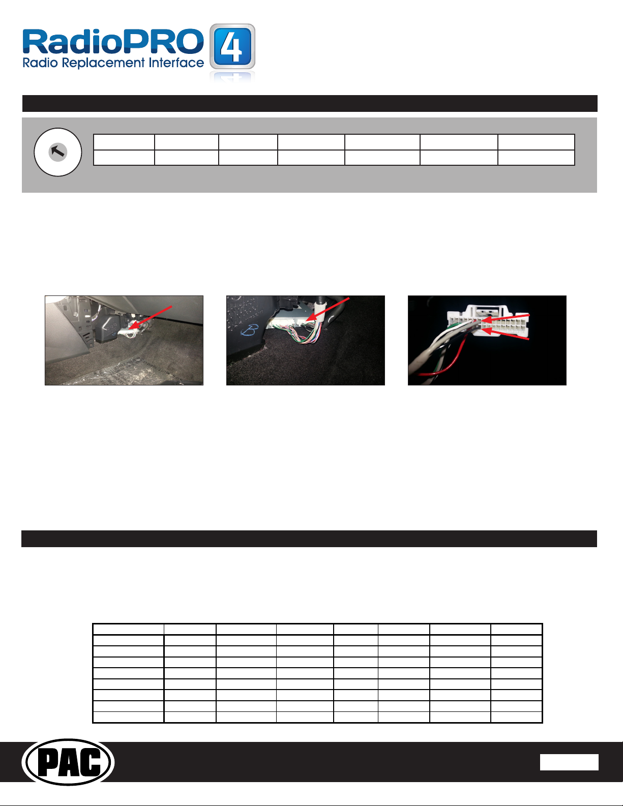
Installation:
1. Follow the instructions from the
RP4-NI11 installation manual for the
wire connections from the RP4-NI11
into the aftermarket radio harness.
Only the primary 24 pin connector
and the black 16 pin RP4-NI11
connectors will be used (see Fig.1).
2. Cut the Pink (CAN +) and
Pink / Black (CAN -) wires between
the RP4-NI11 connector and where
the wires split to go to the 3 unused
connectors (see Fig. 1).
3. Connect the Pink wire (from step
2) to the Light Blue wire (CAN +) in
pin 41 of the 40 pin radio connector
(see Fig. 2).
4. Connect the Pink / Black wire (from
step 2) to the Light Green wire
(CAN -) in pin 21 of the 40 pin radio
connector (see Fig. 2).
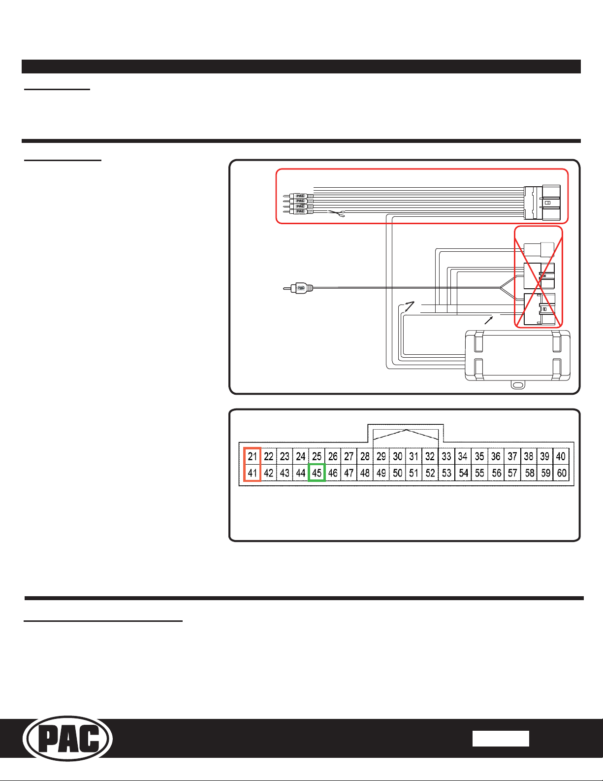
5. Only necessary when using a
reverse camera: Locate the Green
(Reverse +) wire in the Black 16
pin RP4-NI11 connector that goes
to a junction near the (unused) 24
pin connector, with one side going
to the aftermarket radio wiring, one
side going to the (unused) 24 pin
connector, and one side going to the
(unused) 32 pin connector. Cut the
Green wire between the junction and
Cut for Non-Bose systems
Cut Pink and
Pink / Black
Cut Green
X
X
X
These Connectors
Not Used
This Connector
Is Used
Fig. 1
the (unused) 32 pin connector (see Fig. 1).
6. Connect the Green wire (from step 3) to the Green wire (Reverse +) in pin 45 of the 40 pin radio connector (see
Fig. 2).
Fig. 2
Connector Viewed From Wire Side
Pin 21 CAN - (Light Green) Pin 45 Rev + (Green)
Pin 41 CAN + (Light Blue)
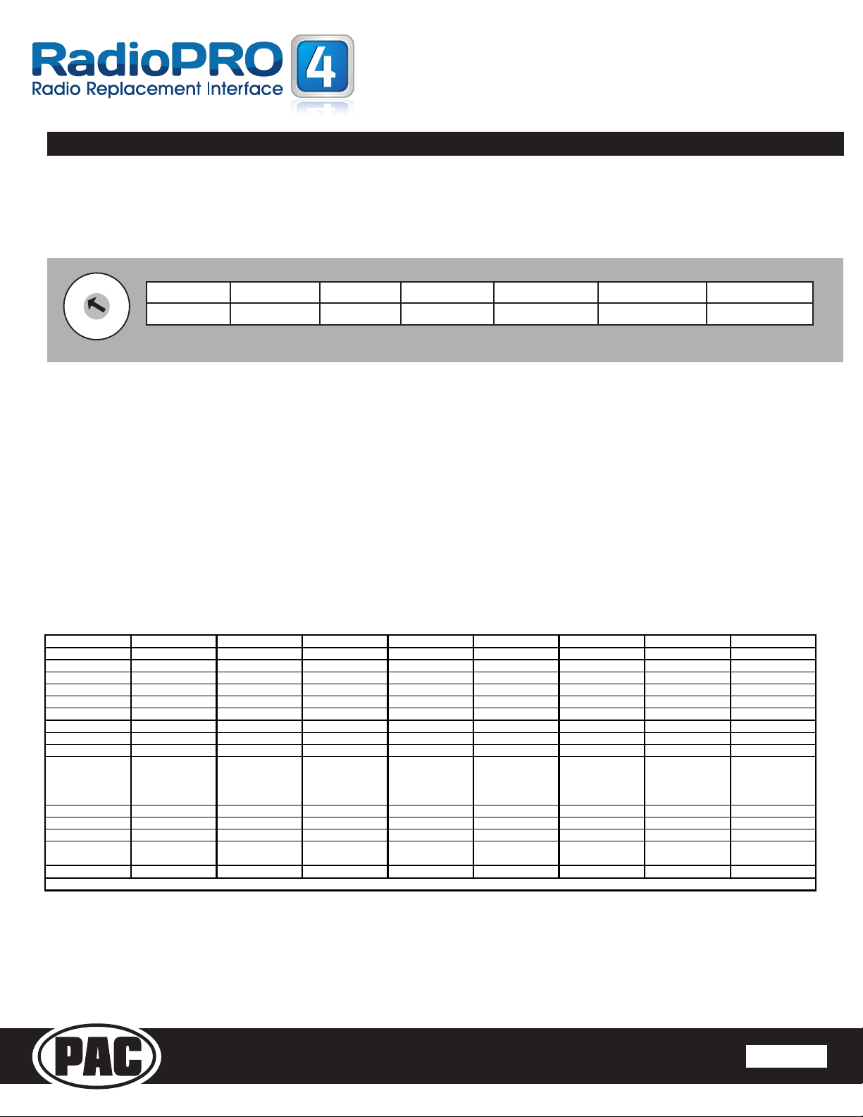
Testing and Verication:
1. Turn on the ignition and press audio steering wheel control buttons to verify the LED on the RP4 NI11 ashes
to indicate that it recognizes the button commands. If the LED does not ash, verify the CAN + and CAN -
connections to the Pink and Pink / Black wires on the RP4-NI11, and verify the RP4-NI11 is using rmware
Revision 4 or higher.
2. Test the Green reverse output connector by verifying the wire is providing a 12 volt output when the ignition is on
and the vehicle is in reverse.


Technical Bulletin
Default Steering Wheel Function Update
\
I
The default function
of
the factory "Voice" steering wheel button, in all RadioPRO applications, has been
updated to launch Siri
or
the Google equivalent for all aftermarket radios that support this function.
You
no
longer need to re-assign the buttons in order for this function to work.
However, if you do wish to re-assign any
of
the buttons, please use the updated function table below as a
reference.
You
can always visitwww.pac-audio.com and search foryourproduct to see the latest, most up-to
"'.date
instruction manuals.
Aloine
JVC
Kenwood
Clarion
Other
•
Pioneer
Sonv
Fusion
1 Volume+ Volume+ Volume+ Volume+ Volume+ Volume+ Volume+ Volume+
2 Volume- Volume- Volume- Volume- Volume- Volume-
Vo
lume- Volume-
3
Mute Mute
Mute
Mute
Mute Mute
Mute Mute
4 Preset+
Source Source Source
Preset+
Preset+ Preset+
Source
5 Preset- Track+
Plav
Search+
Preset
-Preset-
Preset
-
Track+
6
Source
Track
-Track+
Search
-
Source
Source
Source
I
End
Call
Track
-
7 Track+
Band
I Disc+
Track
-
Band
Track+
Track+
Track+
Audio
8 Track-
Preset
/
Disc
-
Disc
/ FM+
Send
I
End
Track
-
Track-
Track-
Power
9
Power
Select
Disc/
AM
-
Send
Band
Band
Band
10
Enter
/
Play
.
Attenuation
Answer
End
Answer••
Phone
Menu
Power
I
End
Call
11
Band
/
Proaram
Phone
Receive
Vo
i
ce
Voice
End**
Answer
Call
Voice
/Answer/
End
Call
12
Receive
Phone
Reject
On
Hook
PTT**
End
Call
Vo
i
ce
(Android
Auto
&
Car
I
Plav)
Answer
/
End
Call***
13
End
Voice
Off
Hook
Vo
i
ce
14
Voice
Power
Mute
15
Preset+
•
Dual
/
Axxera,
Jensen,
Rockford
Fosgate
.,.
Jensen
ONLY
...
XAV-AX100
/
200
Only
Other manuals for RadioPRO4
1
This manual suits for next models
1
Table of contents
Other PAC Automobile Accessories manuals
Popular Automobile Accessories manuals by other brands

Prorack
Prorack K540 Fitting instructions

Whispbar
Whispbar K890W Fitting instructions

Directed Electronics
Directed Electronics DB3 installation guide

Whelen Engineering Company
Whelen Engineering Company Cenator HC installation guide

Brainz
Brainz 38543 instruction manual

Steinhof
Steinhof F-306 FITTING AND OPERATION MANUAL

Whispbar
Whispbar K584W Fitting instructions

Phonocar
Phonocar 4/130 instruction manual

Bosch
Bosch T50028 Original instructions

Ecliptech
Ecliptech Shift-I Installation & quick start guide

Whelen Engineering Company
Whelen Engineering Company Freedom IV Mini Rota-Beam installation guide

DICE
DICE i-MOST-Porsche user manual