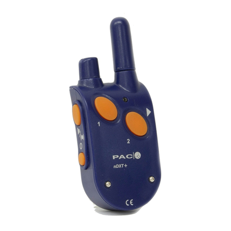
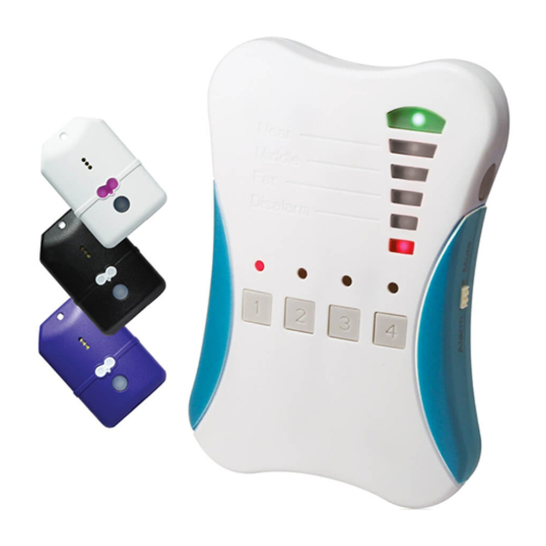
PAC F100 User manual


Table of Contents
1. Introduction
2. Kit Contents
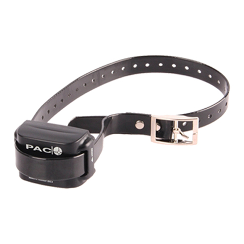
3. Collar Unit Features
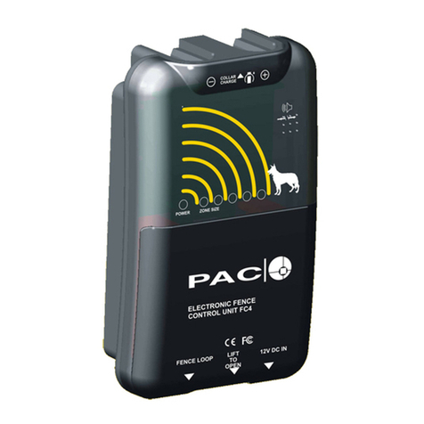
4. Control Unit: Features and Fixing
5. Other Requirements
6. How the system works
7. Layout Overview
8.Choosing the Route
9.Loop Wire Installation:Active Zone/Positioning
10.Avoid Signal Pick-up!
11.Tips for laying the wire
12.Other tips for a tidy installation
13.Joining the Loop wire
14.Twisting the Loop Wire
15.Locating the Control Unit
16.Linking the Control Unit
17.Typical Installation example
18.Fitting the Collar and Maintenance
19.Recharging The Collar
20.Using the RESET magnet
21.System Set-up: Testing
22.System Set-up: Changing the Zone Size
23.Training: Set-up and familiarisation
24.Training: Introduction to the new system
25.Training: Confirmation and Reassurance
26.Going Off-site
27.Troubleshooting: Collar Problems?
28.Troubleshooting: Loop Wire Problems?
29.Troubleshooting: Control Unit Problems?
1
made in EU
printed in EU
© PAC Products Ltd. 2004
Introduction
Introduction
Congratulations on your decision to buy a PAC Electronic Fence. PAC has over 10 years of experience
in the design, manufacture and supply of dog containment and training equipment for professionals,
enthusiasts and pet owners alike. Many thousands of PAC clients will testify to our enormous success
through innovation, reliability and service. PAC is the most popular brand of fence, since it is so easy
to install, and has negligible running costs.
electronic fence

Kit Contents 2
a) Control Unit
b) Collar Unit
c) Mains power adaptor
d) Charging leads
(note attached reset magnet)
e) Loop-wire connector kit
(crimp OR screw-join)
f) Neon tester (p27)
g) Pointed probes
(see Collar Unit features)
h) Wall fixings
NB Loop-wire is not normally
supplied with the kit see p5
i) screwdriver

Collar Unit Features 3
a) Collar unit (waterproof)
b) Probe assembly
c) Status indicator
d) Reset contact point (activated by magnet attached
to charging lead, see page 20.)
e) Pointed probes for longhaired coats.
f) Fitted probes for normal coats.

4
g) ‘Under 500m’ terminal
h) Common terminal
i) ‘Over 500m’ terminal
j) Use supplied template to mark
wall for fixings into wood or masonry
NB Install undercover/indoors.(p15)
a) Power input socket
b) Power supply indicator
c) Loop-wire zone display
d) Loop-wire zone adjustment
e) Collar charging socket
f) Charge timer button
Control Unit: Features and Fixing

Other Requirements 5
A. Loop-wire (available from most electrical wholesalers in 100 metre reels)
Specification - 1.5mm2multi-cored PVC cable 7/0.53 BS 6491X (or equivalent).
See table for minimum number of reels required.Add approximately 20% to
allow for awkward shaped perimeters.
B. (Recommended) Boundary-demarcation plastic-tape, temporarily to help
the dog recognise the new boundaries during the initial training period. See
Training section page 23.) Available from Plant Hire shops and Sports outlets.

The electromagnetic, active zone (A) comprises 3 sub-zones. The collar
reacts immediately according to time and distance from the wire (w).
a) Tone-only followed after 2 seconds by low level stimulus.
b) Tone plus immediate medium level stimulus.
c) Tone plus immediate high level stimulus (10 seconds max. for humane
reasons)All deterrent activity ceases immediately the dog withdraws, and
the collar automatically resets
6
How the system works

7
Layout Overview
a) The wire must form a complete loop around the area to be enclosed, starting and
finishing at the Control Unit.
b) Before attempting to bury or otherwise fix the wire in place, lay the complete loop
on the surface and test that your chosen route will work to your expectation (see
p21). This will facilitate any necessary later adjustment to the proposed route.
c) When satisfied, firm up the installation (see pages 11 &12)

8
Choosing the Route
a) Follow natural boundary markers e.g. fence, wall, line of bushes or
trees or the edge of the lawn.
b) Crossing the lawn, for example, is not recommended, since the dog
will not easily recognise an arbitrary boundary.

9
Loop Wire Installation:Active Zone/Positioning
a) Tacked to a boundary feature. Optimum position = dog collar height.
b )Laid on the surface (needing a larger zone size).
c) Buried just below the surface. 50-100mm (2-4”)
d) In some areas with high mineral content it will not be possible to bury the wire
much below the surface due to local, environmental factors that can affect the zone
shape and size.

10
Avoid Signal Pick-up!
a) Do not lay the cable parallel to incoming conductive (metal) services –
e.g. electricity cables or water pipe – since this might cause stray signals
to affect the dogs collar in the house.
b) To avoid this, always cross such services at right angles.
c) If the loop-wire is attached to a wire mesh fence it will pick-up and
radiate the signal. This will not be important if the mesh fence is part
of the boundary.

Tips for laying the wire 11
If burying the cable or laying it on the surface, consider …
a) protecting it from excessive wear (e.g. when running across a gravel
driveway) or accidental damage (e.g. by a gardener’s spade… or
lawn mower) by running it through a protective sheath e.g. a
plastic (water-) pipe (page 12).
b) using coloured wire for better visibility when clipping the hedge.

Other tips for a tidy installation 12
If using plastic piping to sheath the wire, to avoid difficulty in threading
the wire through long sections:
a) use shorter sections of pipe, joining them using short sleeves of
larger cross-section pipe.
b) Use cable clips (available from all electrical wholesalers) to tack
the loop-wire to fences or walls.

Joining the Loop wire 13
Standard connector:
a) Strip both ends of the wire to 5mm (¼”)
b) Slide shrink-sleeve over one of the wires
c) Join the two ends together using the metal connector
d) Wrap joint tightly with the PVC tape
e) Slide sleeve over the assembly and shrink it with gentle heat.
Heatsealtm Connector: i) strip as above, ii) place both ends into
centre of connector iii) crimp with crimping tool iv) heatseal

14
Twisting the Loop Wire
a).When the loop signal needs to be cancelled twist an incoming
and outgoing section
b) Ensure twists are close enough to cancel signal

15
Locating the Control Unit
Position the Control Unit somewhere under cover, protected from the
weather where it can be seen on a regular basis to check
a)power source
b)the continuity of the loop and
c)the nominal size of the zone
An ideal place would be next to the door through which the dog(s) go

16
Linking the Control Unit
a) Twist the loop-wire tails all the way from the perimeter to the Control Unit.
b) Connect loop-wire tails to the Control Unit – One end to the middle (common) terminal and the
other to the appropriate, ‘Over-‘ or ‘Under-500 metres’. Never use the ‘Over 500 metres’ terminal
for loops of less than 500 metres in length.
c) Connect power supply from the mains adapter or car battery to the control unit.
d) Turn power on and check that power–on and Zone LED(s) light up.

a)Loop-wire tails are twisted all the way from the perimeter to the control unit
b)Loop-wire can be twisted and re-opened to create a satellite loop around
the swimming pool and/or flowerbed. Twisted section gives dog free access.
c)The wire can be buried and sheathed in a protective, plastic conduit to run
beneath the driveway. Signal is still active.
d)Gentle curves on the corners reduce signal interference.
17
Typical Installation example

18
Fitting the Collar and Maintenance
a) Ensure that the collar is correctly and snugly positioned on the dog’s
neck. Inspect for skin irritation on a daily basis. For longhaired breeds
use the more pointed probes.
b) Never fit the collar to your dog when near to the zone!
c) If soiled or exposed to salt water, wash with fresh water and brush.
Other manuals for F100
1
Table of contents
Other PAC Pet Care Product manuals
Popular Pet Care Product manuals by other brands

Petsafe
Petsafe Healthy Pet Siply Feed PFD00-14574 quick guide

Pet Essentials
Pet Essentials Deluxe Cat Tree Assembly instructions

Patio Pacific
Patio Pacific Endura Flap installation instructions

camry
camry CR 7431 user manual

Savic
Savic DOG BARRIER instructions

mimsafe
mimsafe Multicage Single Assembly instructions