OPTION A VIRTUAL WIRE DEPLOYMENT
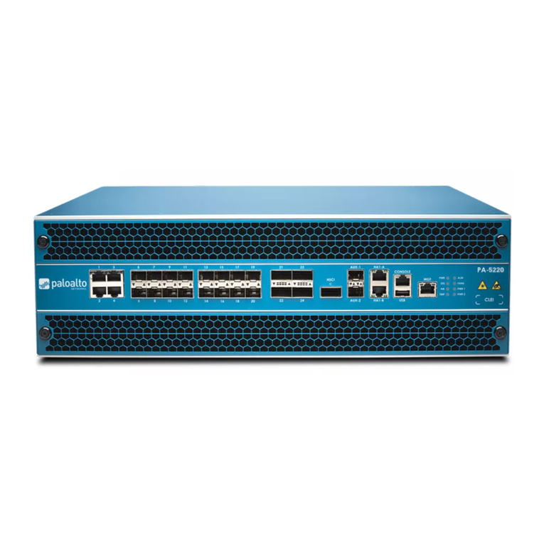
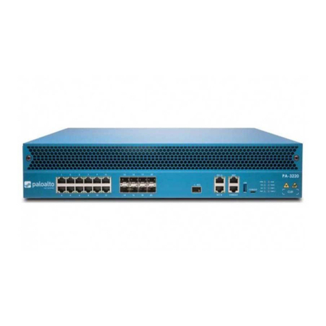
The default configuration of the PA-3000 Series firewall is a virtual wire between ports 1 and 2, which enforces
security policies. No configuration is required for this basic setting. Proceed to Performing the Final Setup.
OPTION C LAYER 3 DEPLOYMENT
CONFIGURE THE INTERFACES
Obtain two IP addresses for ports 1 and 2 on the PA-3000 Series firewall from your network
administrator. This example uses IPv4 addresses; IPv6 is also supported.
Select Network > Interfaces, click ethernet1/1 and select Layer 3 from the Interface Type drop-
down.
Click the IPv4 tab and select Static. Click Add in the IP field and enter the IP address and subnet
mask for port 1 in the IP field. For example, 10.1.1.1/24.
Click OK to save the changes.
Select ethernet1/2 and select Layer 3 from the Interface Type drop-down.
Click the IPv4 tab and select Static. Click Add in the IP field and enter the IP address and subnet
mask for port 2 in the IP field. For example, 10.1.2.1/24.
Click OK to save the changes.
CONFIGURE THE SECURITY ZONES
Select Network > Zones and Add a new zone. Enter
trust
as the Name and select Layer 3 as the Type.
In the Interfaces section, click Add, select ethernet1/2 and then click OK.
Add another zone named
untrust
and choose Layer3 from the Type drop-down list.
In the Interfaces section, click Add, select ethernet1/1 and then click OK.
CONFIGURE THE VIRTUAL ROUTERS
You must assign a virtual router to all Layer 3 interfaces (including the loopback interface) to enable
routing.
Select Network > Virtual Routers and then click default.
In the Interfaces section, click Add and add ethernet1/1 and ethernet1/2.
Add a default route by clicking the Static Routes tab and click Add. Enter a Name for the static route
and enter a route in the Destination field (for example, 0.0.0.0/0).
Add static routes and other routing protocols as needed and click OK when finished.
Commit the configuration and proceed to Performing the Final Setup.
OPTION B LAYER 2 DEPLOYMENT
CONFIGURE THE INTERFACES
Select Network > Interfaces and click the Ethernet tab.
Click ethernet1/1 and select Layer 2 from the Interface Type drop-down and then click OK.
Click ethernet1/2 and select Layer 2 from the Interface Type drop-down and then click OK.
CONFIGURE THE SECURITY ZONES
Select Network > Zones and Add a new zone. Enter
trust
as the Name and select Layer 2 as the Type.
In the Interfaces section, click Add and select ethernet1/2 and then click OK.
Add another zone named
untrust
and choose Layer2 from the Type drop-down.
In the Interfaces section, click Add and select ethernet1/1 and then click OK.
CONFIGURE THE VLANS
Select Network > VLANs and then click Add and name the new VLAN
vlan-1
.
In the Interfaces section, click Add and add ethernet1/1 and ethernet1/2 and then click OK.
Commit the configuration and proceed to Performing the Final Setup.
Choose a Deployment Option
•OPTION A: Virtual Wire deployment—Choose this option to transparently place the PA-3000 Series firewall
between two devices where no routing, switching, or NAT is required.
•OPTION B: Layer 2 deployment—Choose this option to deploy the PA-3000 Series firewall in a Layer 2
environment where switching is required.
•OPTION C: Layer 3 deployment—Choose this option to deploy the PA-3000 Series firewall in a Layer 3
environment where routing and NAT are required.
1
2
3
4
5
6
7
8
10
11
12
13
14
15
ethernet1/2 ethernet1/1User
Network Internet
PA-3000 Series
9
PREREQUISITE LAYER 2 AND LAYER 3 DEPLOYMENTS
To deploy the firewall in Layer 2 mode (option B) or Layer 3 mode (option C), you must first delete the default virtual
wire configuration in the following order:
To delete the default security policy, select Policies > Security, select
rule1
, and click Delete.
Next, delete the default virtual wire by selecting Network > Virtual Wires, selecting the virtual wire and
clicking Delete.
To delete the default trust and untrust zones, select Network > Zones, select each zone and click Delete.
Finally, delete the interface configuration by selecting Network > Interfaces and then select each
interface (ethernet1/1 and ethernet1/2) and click Delete.
Commit the changes and continue to Option B Layer 2 Deployment or Option C Layer 3 Deployment.
1
2
3
4
5
1
2
3
4
5
6
7
8
10
9
16
