manuals.online logo
Brands
  1. Home
  2. •
  3. Brands
  4. •
  5. Panasonic
  6. •
  7. Intercom System
  8. •
  9. Panasonic VL-SWD501UBX User manual

Panasonic VL-SWD501UBX User manual

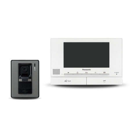
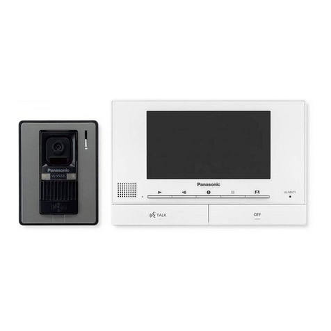
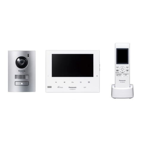
Wireless Video Intercom System
Key Features
• Wireless Handset:
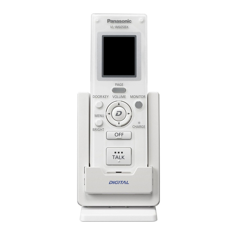
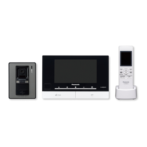
Check visitors on Wireless Monitor, respond promptly and talk from living room, kitchen, everywhere home and while you are doing something else. UP to 6 wireless
monitor connectable. Max wireless range is 100m with no obstacles. You can add on repeaters expand the range. UP to 2 DECT repeater connectable.
• Large Touch Panel:
The main monitor has a large, 5 inch wide screen that clearly shows each visitor's face. You can simply touch the screen to activate an approximate 2x zoom
horizontally and vertically.
• Electric Lock Release Support for Gate: The gate or door lock can be easily and quickly released even from the second oor of the house.
• Wide-Angle Camera: Wide-angle lens covers approximately 170 degrees horizontally and 115 degrees vertically.
• SD Card Recording:
Automatically record video images of visitors to SD card. It will record up to 3,000 visitors (30 seconds per visitor). (The SD Memory Card is sold separately.)
• Wireless Sensor Cameras:
By installing the optional DECT Wireless Sensor Camera, you can use human (heat) and motion sensors to monitor locations that you are concerned about.
UP to 4 wireless sensor camera connectable.
Door Station
(Doophone)
VL-V554BX
VL-V554UBX
DECT Repeater
VL-FKD2BX
Lobby Station
VL-V590BX
VL-V590CX
Wireless
Monitor Station
(Sub monitor)
VL-WD613BX
Main Monitor
Station
(Main monitor)
VL-MWD501BX
Wireless Sensor Camera
VL-WD812BX
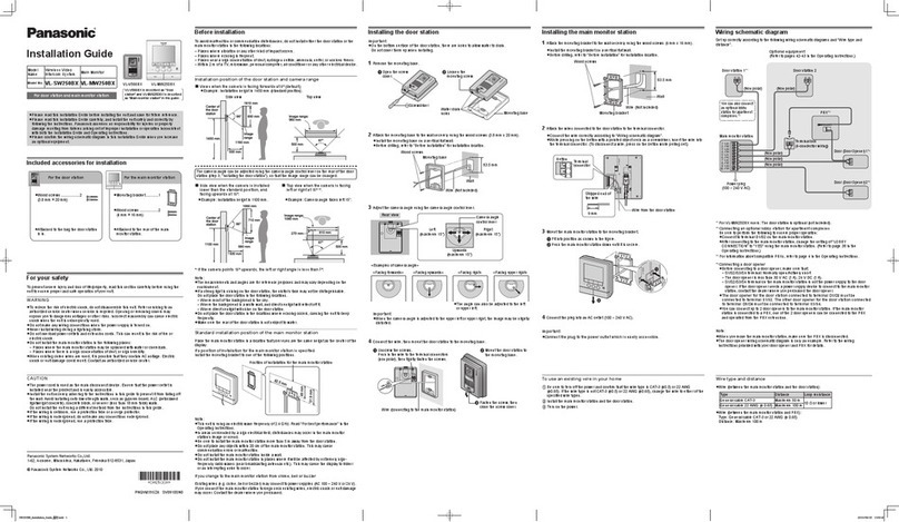
For the Sub Monitor: AC adaptor × 2 (PNLV226BX [2 pin AC plug] / PNLV226E [3 pin AC plug]), Rechargeable batteries × 2, Charger × 1
For the Door Station: <VL-V554BX> Mounting base × 1 & screw (3.8 mm x 20 mm) × 2, Screw (4 mm x 12 mm) × 4, Name plate × 2, Hex wrench × 1
<VL-V554UBX> Flush mounting box × 1, Screw (4 mm x 25 mm) × 4, Name plate × 2, Hex wrench × 1
For the Main Monitor Station: Power supply unit* (VL-PS241) × 1, Mounting bracket × 1, Cable binder × 1, Screw (4 mm x 16 mm) × 2
*Including AC cable × 2, Cable binder × 1, Screw (4 mm x 40 mm) × 2
Wiring Schematic Diagram
Accessory Information
Optional Accessories Relative Product
Up to 20 Main
monitors
connectable
POWER SUPPLY UNIT
DOORPHONE 1
MAIN MONITOR
DOORPHONE 2
220-240 V AC
Connection device for option output (A contact)
• When using an optional lobby station, this terminal is used by the lobby station. (In this case, connection
devices for option output (A concatc) cannot be connected.)
NP: Non-polarised
12 V AC/DC
12 V AC/DC
Electric lock
Electric lock
(Optional lobby station can be connetcted.)
24 V DC
A
B
D
C
C
NP NP
NP
NP
NP
NP
Power
supply
Power
supply
MAIN MONITOR STATION LOBBY STATION
Electric lock
30 V AC/
24 V DC
NP
NP
NP
<Rear view>
<Rear view>
Power
supply
Wire type and length
Wiring run Wire type*1
Diameter Length (Max.)
Main monitor – Doorphone
φ 0.65 mm 22 AWG 100 m
φ 1.0 mm 18 AWG 130 m
φ 0.5 mm CAT 5 50 m
Main monitor – Power supply unit φ 0.65 mm 22 AWG 10 m
φ 1.0 mm 18 AWG 20 m
Doorphone – Electric lock*2φ 0.5 mm - φ 1.2 mm (24 AWG - 17 AWG) According to speci cation of connected device.
Main monitor – Connection device for
option output (A contact)*2φ 0.5 mm - φ 1.2 mm (24 AWG - 17 AWG) According to speci cation of connected device.
Wireless sensor camera –
Power supply unit –φ 0.65 mm 22 AWG 50 m
φ 1.0 mm 18 AWG 100 m
Wireless sensor camera –
External sensor –φ 0.5 mm - φ 0.8mm (24 AWG - 20 AWG) According to speci cation of connected device.
Must be no longer than 20 m.
*1 Type: Single-pair cable with outer sheath (jacket) Conductor: Copper
solid
• A certi ed power supply wiring has to be used with this equipment.
The relevant national installation and/or equipment regulations shall
be considered. A certi ed power supply wiring not lighter than ordinary
polyvinyl chloride  exible wiring according to IEC 60227 shall be used.
*2 When using an electric lock or a connection device for option output (A
contact), select a device that meets the following guidelines:
• Electric lock connection terminal (S1/S2):
- N/O dry closure contact
- 12 V AC/DC, less than 1 A
• Connection device for option output (A contact) terminal (OUT1/OUT2):
- 24 V AC/DC, less than 0.3 A (minimum contact: 5 V DC 1 mA)
VL-SWD501BX/UBX
B
A
C
D
Specications
Model Composition
Installing the Main Monitor
Installing the Doorphone
Installing the Wireless Camera
VL-MWD501BX VL-V554BX (Surface mount)
VL-V554UBX (Flush mount) VL-WD613BX VL-PS241
Model number and name Main Monitor Station (Main monitor) Door Station (Doorphone) Wireless Monitor Station (Sub monitor) Power Supply Unit (part)
Main body Charger
Dimensions
Power source Power supply unit (VL-PS241)
24 V DC, 0.5 A
Power supplied by the main monitor
20 V DC, 0.23 A Rechargeable Ni-MH (AAA x 2)
AC adaptor (PNLV226BX/PNLV226E)
Input: 220-240 V AC, 0.1 A, 50/60 Hz
Output: 5.5 V DC, 0.5 A
Input: 220-240 V AC, 0.2 A, 50/60 Hz
Output: 24 V DC, 0.6 A
Power consumption Standby: Approx. 1.4 W
During operation: Approx. 10 W - -
Standby: Approx. 0.4 W (when the sub
monitor is not placed in the charger)
During charging: Approx. 1.4 W
-
Dimensions (H x W x D)
(Excluding protruding sections) 180 x 165 x 21 mm
VL-V554BX: 169 x 118 x 30 mm
VL-V554UBX: 169 x 118 x 16.5 mm
(excluding sections embedded into the wall)
173 x 52 x 30 mm 43 x 81 x 76 mm 104 × 100 × 54 mm
Weight 470 g VL-V554BX: 405 g, VL-V554UBX: 345 g 160 g (including the batteries) 70 g (excluding the AC adaptor) 215 g
Operating environment 0 °C to 40 °C, Up to 90 % RH
(Relative Humidity) non condensing
-10 °C to 50 °C, Up to 90 % RH
(Relative Humidity) non condensing
0 °C to 40 °C, Up to 90 % RH
(Relative Humidity) non condensing
0 °C to 40 °C, Up to 90 % RH
(Relative Humidity) non condensing
0 °C to 40 °C, Up to 90 % RH
(Relative Humidity) non condensing
Display Approx. 5 inch, wide colour display -Approx. 2.2 inch, colour display - -
Frequency 1.88 GHz to 1.90 GHz -1.88 GHz to 1.90 GHz - -
Option output (A contact)
Rated load: 24 V AC/DC, 0.3 A or lower
Minimum applicable load: 5 V DC, 0.001 A
(Output when there is a call from the doorphone)
----
Viewing angle -Horizontally: Approx. 170°
Vertically: Approx. 115° ---
Installation method Wall mount
(mounting bracket supplied)
VL-V554BX: surface mount
(mounting base supplied)
VL-V554UBX:  ush mount
( ush mounting box supplied)
---
IP rating / IK rating -IP54*3 / Compliant with IK07 ---
External material Flame retardant ABS and PS resin
Aluminium and  ame retardant PC+PS resin
ABS resin ABS resin Flame retardant PC+ABS resin
VL-WD812BX VL-FKD2BX
Model number and name Wireless Sensor Camera DECT Repeater
Dimensions
Power source Power supply unit (VL-PS241)
24 V DC, 0.4 A
AC adaptor (PQLV219BX/PQLV219E)
Input: 220-240 V AC, 0.1 A, 50/60 Hz
Output: 6.5 V DC, 0.5 A
Power consumption
During standby: Approx. 1.5 W
During operation: Approx. 4.5 W (when
the LED lights are not lit), Approx. 8 W
(when the LED lights are lit)
During standby: Approx. 1.5 W
During operation: Approx. 2.3 W
(when transmitting)
Dimensions (H x W x D)
160 x 118 x 290 mm
(when the camera is front facing and
including the wall mount bracket)
82 x 111 x 39 mm
Weight 960 g 88 g (excluding the AC adaptor)
Operating environment
-20 °C to 50 °C,
Up to 90 % RH (Relative Humidity)
non condensing
0 °C to 40 °C
Up to 90 % RH (Relative Humidity)
non condensing
Frequency 1.88 GHz to 1.90 GHz 1.88 GHz to 1.90 GHz
Installation method Wall mount
(wall mount bracket supplied) -
Transmitting range Approx. 100 m (line-of-sight distance
from the main monitor)
Approx. 100 m (line-of-sight distance
from the main monitor)
Minimum illuminance required 1 lx*1-
Image sensor 0.3 M pixel CMOS -
Lighting method 2 white LED lights*2-
Angular eld of view
(camera angle)
Horizontal: Approx. 53°
Vertical: Approx. 41° -
Sensor detection range
• Heat sensor (when the surrounding
temperature is approx. 20°)
Horizontal: Approx. 63°, vertical: Approx.
20°, detection range: Approx. 5 m
• Motion detection sensor Horizontal:
Approx. 53°, vertical: Approx. 41°
-
Sensor detection method Pyroelectric infrared sensor
(heat sensor) and motion detection -
IP rating IP54*3-
Adjustable mounting angles
Horizontal: ±90°, vertical: facing forward
- facing down approx. 60°
(adjustable when mounting)
-
Heat sensor adjustable angles Manually adjustable to 2 angles -
External material PC+ABS resin PS resin
VL-SWD501BX VL-MWD501BX x 1, VL-WD613BX x 1, VL-V554BX x 1
VL-SWD501UBX VL-MWD501BX x 1, VL-WD613BX x 1, VL-V554UBX x 1
Attach the mounting bracket to the wall securely.
Install the mounting bracket on a vertical at wall.
MG-DHPL002EN 1406ITP/ZZZ-BX1
Important
– Safety Precaution: carefully read the operating instructions and installation manual before using this product.
• The actual product may vary slightly from photograph.
• Weights and dimensions are approximate.
• Design and Specifications are subject to change without notice.
• These products may be subject to export control regulations.
*1 The minimum illuminance required when the camera’s [Brightness] setting is set to [+3].
*2 Approx. 8.5 lx when 3 m in front of the camera, and approx. 4 lx when 3 m away and 20° to the left or right of the camera.
*3 Water resistance is only assured if the camera is installed correctly according to the instructions in the Installation Guide, and
appropriate water protection measures are taken. Do not install the camera in areas directly exposed to water or rain.
Vertical,  at wall
Screws
Hole in wall
83.5 mm
60 mm
7 mm
50 mm
Mounting bracket
Mounting base
(accessory)
Wire (locally procured)
Wall
83.5 mm
Screw × 2
Install the mounting base on a vertical at wall.
• VL-V554BX (Surface mount)
Mounting screws
(locally procured) × 4 46 mm
83.5 mm
Cable access hole
DC cable
Screws (accessory)
Flush mounting box
(accessory)
• VL-V554UBX (Flush mount)
100 mm
151 mm
37 mm
165 mm 21 mm
180 mm
118 mm
Up to 2 Up to 6
30 mm
16.5 mm
35.8 mm
169 mm
52 mm 30 mm
173 mm
81 mm 76 mm
43 mm
100 mm
104 mm
*Indoor use only.
118 mm
142 mm 94 mm
290 mm
160 mm
111 mm 39 mm
82 mm
Up to 4 Up to 2
This manual suits for next models

1

Other Panasonic Intercom System manuals

Panasonic VL-SWD501 User manual

Panasonic

Panasonic VL-SWD501 User manual

Panasonic VL-VN1500 User manual

Panasonic

Panasonic VL-VN1500 User manual

Panasonic VL-V900 User manual

Panasonic

Panasonic VL-V900 User manual

Panasonic Windea HA D Series User manual

Panasonic

Panasonic Windea HA D Series User manual

Panasonic VL-SV71 User manual

Panasonic

Panasonic VL-SV71 User manual

Panasonic VF540-V User manual

Panasonic

Panasonic VF540-V User manual

Panasonic WX-CC411 User manual

Panasonic

Panasonic WX-CC411 User manual

Panasonic VL-WD619 User manual

Panasonic

Panasonic VL-WD619 User manual

Panasonic VL-MW274 User manual

Panasonic

Panasonic VL-MW274 User manual

Panasonic KX-T206JT User manual

Panasonic

Panasonic KX-T206JT User manual

Panasonic WX-CC411BP User manual

Panasonic

Panasonic WX-CC411BP User manual

Panasonic KX-T7775 User manual

Panasonic

Panasonic KX-T7775 User manual

Panasonic VL-SV70 User manual

Panasonic

Panasonic VL-SV70 User manual

Panasonic VL-SVD302KL Operator's manual

Panasonic

Panasonic VL-SVD302KL Operator's manual

Panasonic KX-T7765X User manual

Panasonic

Panasonic KX-T7765X User manual

Panasonic VL-SWD273 Operating manual

Panasonic

Panasonic VL-SWD273 Operating manual

Panasonic VL-VC3900BX Technical manual

Panasonic

Panasonic VL-VC3900BX Technical manual

Panasonic VL-SW102BX User manual

Panasonic

Panasonic VL-SW102BX User manual

Panasonic VL-SVN511 Series User manual

Panasonic

Panasonic VL-SVN511 Series User manual

Panasonic KX-T206JT User manual

Panasonic

Panasonic KX-T206JT User manual

Panasonic VL-GM001 Operating instructions

Panasonic

Panasonic VL-GM001 Operating instructions

Panasonic VL-SVN511 Series User manual

Panasonic

Panasonic VL-SVN511 Series User manual

Panasonic VL-VF580 User manual

Panasonic

Panasonic VL-VF580 User manual

Panasonic VL-V901 User manual

Panasonic

Panasonic VL-V901 User manual

Popular Intercom System manuals by other brands

HME Clear-Com Tempest 2400 quick start guide

HME

HME Clear-Com Tempest 2400 quick start guide

Atlas VPB-1A Brochure & specs

Atlas

Atlas VPB-1A Brochure & specs

Wander Control Systems KP-1 installation manual

Wander Control Systems

Wander Control Systems KP-1 installation manual

Chamberlain LiftMaster 833-1LM manual

Chamberlain

Chamberlain LiftMaster 833-1LM manual

SSS Siedle AS-Ta-64/1 System manual

SSS Siedle

SSS Siedle AS-Ta-64/1 System manual

Farfisa SE7PG quick start guide

Farfisa

Farfisa SE7PG quick start guide

FARFISA INTERCOMS ZHEROS ZH1252B manual

FARFISA INTERCOMS

FARFISA INTERCOMS ZHEROS ZH1252B manual

Sena SMH5 MULTICOM user guide

Sena

Sena SMH5 MULTICOM user guide

SSS Siedle BCVU 850-1-0 E Product information

SSS Siedle

SSS Siedle BCVU 850-1-0 E Product information

Farfisa EX3252PLC manual

Farfisa

Farfisa EX3252PLC manual

Tema Telecomunicazioni AA-500 Series TECHNICAL MANUAL - INSTALLATION PRELIMINARY DOCUMENTATION

Tema Telecomunicazioni

Tema Telecomunicazioni AA-500 Series TECHNICAL MANUAL - INSTALLATION PRELIMINARY DOCUMENTATION

GVS S Series user manual

GVS

GVS S Series user manual

Valcom VIP-581A-IC quick start guide

Valcom

Valcom VIP-581A-IC quick start guide

Acutron HC-30 Installation and operation manual

Acutron

Acutron HC-30 Installation and operation manual

Cyfral SMART-5PG instruction manual

Cyfral

Cyfral SMART-5PG instruction manual

Commax CIOT-L20M user manual

Commax

Commax CIOT-L20M user manual

LAON TECHNOLOGY LT750 Series quick reference

LAON TECHNOLOGY

LAON TECHNOLOGY LT750 Series quick reference

Optex iVISION+ IVP-DU installation instructions

Optex

Optex iVISION+ IVP-DU installation instructions

manuals.online logo
manuals.online logoBrands
  • About & Mission
  • Contact us
  • Privacy Policy
  • Terms and Conditions

Copyright 2025 Manuals.Online. All Rights Reserved.