manuals.online logo
Brands
  1. Home
  2. •
  3. Brands
  4. •
  5. Panasonic
  6. •
  7. Touch Terminal
  8. •
  9. Panasonic S-LINK V SL-VTPR Series User manual

Panasonic S-LINK V SL-VTPR Series User manual

Panasonic Industry Co., Ltd.
Panasonic Industrial Devices SUNX Co., Ltd.
https://panasonic.net/id/pidsx/global
Please visit our website for inquiries and about our sales network.
Panasonic Industrial Devices SUNX Co., Ltd. 2022
September, 2022 PRINTED IN JAPAN
SL-VTPR□
Relay Output Terminal
Flexible Wire-saving Link System S-LINK V
INSTRUCTION MANUAL
MJE-SLVTPR No.0085-95V
PRECAUTIONS
7
Short-circuit protective function is not incorporated in the output. If the
output is short-circuited, product breakage or burnout may occur.
●This product has been developed / produced for industrial use only.
●Make sure to carry out wiring and relay replacement in the power supply
OFF condition.
●Make sure to check the wiring before the power supply is switched ON.
If the power supply is switched ON when the wiring is incorrect, there is
a danger of malfunction or damage.
●In case noise generating equipment (switching regulator, inverter mo-
tor, etc.) is used in the vicinity of this product, connect the frame ground
(F.G.) terminal of the equipment to an actual ground.
●Do not run the wires together with high-voltage lines or power lines or
put them in the same raceway. This can cause malfunction due to in-
duction.
●A switch cap is attached to the setting switches area. In case of setting,
remove the switch cap. After setting, attach the switch cap to the setting
switches area.
●This product does not have a dust-proof or water-proof construction.
Do not use the product in places having excessive vapor, dust, etc., or
where it may come in contact with corrosive gas, etc.
●Take care that the product does not come in contact with oil, grease,
organic solvents such as thinner, etc., strong acid, or alkaline.
● Make sure to t the cover before use.
SPECIFICATIONS
6
Notes: 1) This product is incorporated with the PA-N relay manufactured by Panasonic Co.,
Ltd. However, when you replace the relay, you can also use the PhotoMOS relay
manufactured by Panasonic Co., Ltd.
For a detailed description, refer to “ RELAY REPLACEMENT.”
2) If this unit is installed in a control box along with other units, the ambient
temperature may exceed the rated value due to the heat generated by the units.
In this case, make sure that the ambient temperature does not exceed the rated
value by installing a fan, etc.
3) This value can change due to the switching frequency, environmental conditions,
and desired reliability level, therefore it is recommended to check this with the
actual load.
Type 4-channel 8-channel
Item
Model No.
SL-VTPR4 SL-VTPR8
Supply voltage
24V DC±10% (Supplied from S-LINK V controller or separate power supply)
Current consumption 90mA or less
(When all points are ON)
150mA or less
(When all points are ON)
Address setting Using switches, in the range of 0 to 511
Output
Relay contact 1a (Note 1)
• Nominal switching capacity: Under 50V, 3A AC (resister load)
However, if compatibility with the CE / UKCA is not neces-
sary, use of 250V, 3A AC is possible.
30V, 3A DC (resister load)
• Min. switching capacity : 5V 1mA DC (Note 3)
• Electrical life: 100,000 times of operation or more
(rated load, switching frequency of 20 times/min)
• Mechanical life: 20,000,000 times of operation or more
(switching frequency of 180 times/min)
Output operation
The output relay is turned ON if the output signal from the sig-
nal transmission line is turned ON.
Number of output points
4 points 8 points
Output holding function
Incorporated
Ambient temperature
(Note 2)
-10 to +55°C (No dew condensation or icing allowed)
Storage: -20 to +70°C
Ambient humidity 35 to 85% RH, Storage: 35 to 85% RH
Material Enclosure: PC-ABS resin, Cover: Polycarbonate
DIN rail stopper: POM, Relay remover key: POM
Weight Approx. 100g Approx. 160g
Accessory Cover: 1 pc., Switch cap: 1 pc., Relay remover key: 1 pc.
Thank you very much for purchasing Panasonic products. Read this Instruc-
tion Manual carefully and thoroughly for the correct and optimum use of this
product. Kindly keep this manual in a convenient place for quick reference.
●Never use this product in a device for personnel protection.
●In case of using devices for personnel protection, use products which
meet laws and standards, such as OSHA, ANSI or IEC etc., for person-
nel protection applicable in each region or country.
●Before touching this product, remove any electrostatic charge that may
be present on your body. There is a danger of this product getting dam-
aged due to the electrostatic charge.
Please refer to the "S-LINK V User's Manual" for details of the entire
S-LINK V system.
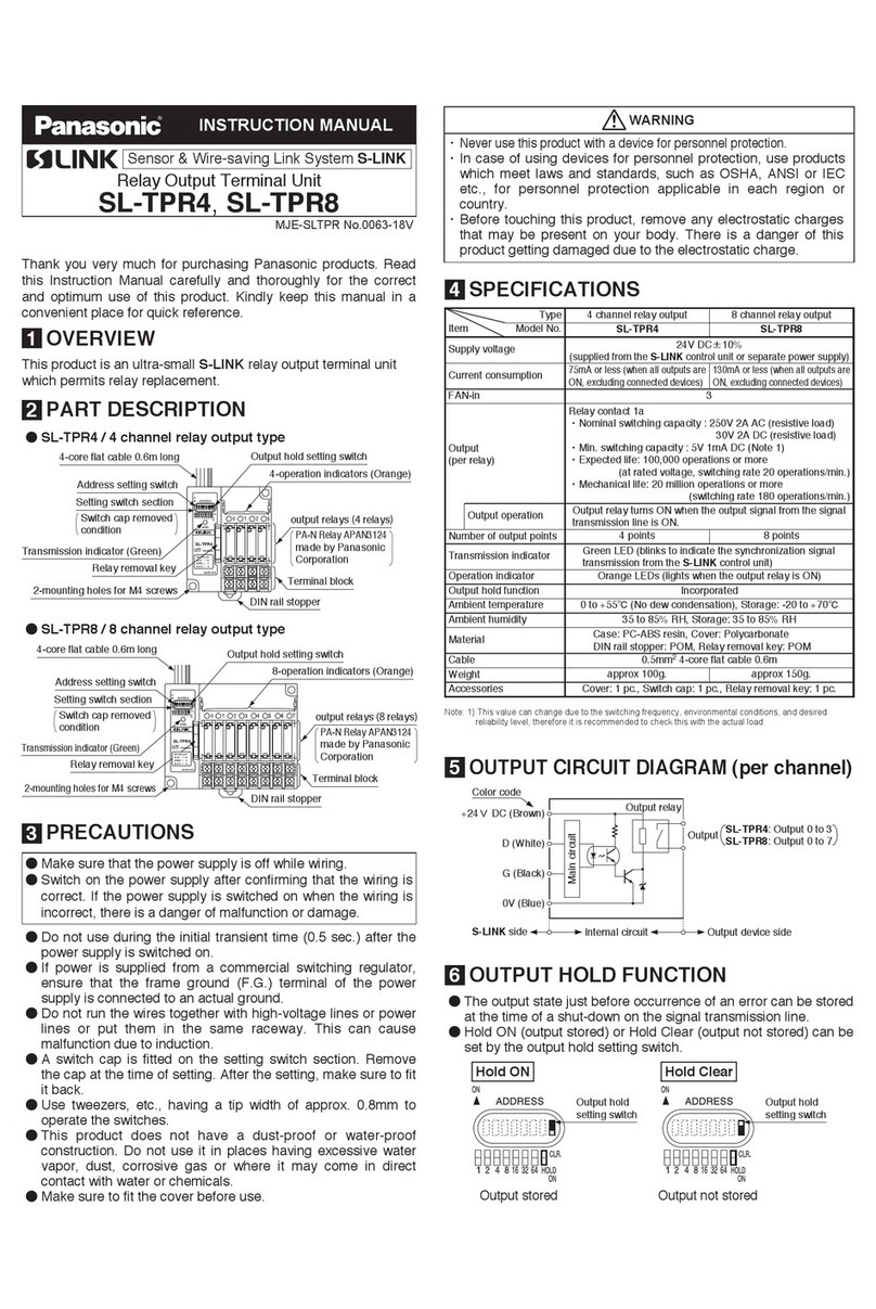
PARTS NAMES AND FUNCTIONS
1
SL-VTPR4 SL-VTPR8
1
2
3
4
6
8
7
5
4-core flat cable, 0.6m long
8
7
5
1
2
3
4
6
4-core flat cable, 0.6m long
Designation Function
1 Address setting switches Used for setting of the terminal address.
2Output holding function
setting switch
Used for setting of the output holding function.
ON: Hold the current output conditions (output holding).
OFF: Will not hold the current output conditions (output OFF).
3 Power indicator (Green) This indicator will light when the power is supplied.
4Transmission indicator
(Green)
This indicator will blink when the synchronization
signal is sent from the S-LINK V controller.
5Operation indicator
(Orange) Lights when each output relay is turned ON.
6 Relay remover key Use this key to remove the output relays.
7 Output relay PA-N relay APAN3124 manufactured by Panasonic
Co., Ltd. (Note)
8 Terminal block Used for connection of output devices.
Note: You can replace the output relays.
For a detailed description, refer to “ RELAY REPLACEMENT.”
MOUNTING
2
<In case of mounting on DIN rail>
Mounting method
1. Push the DIN rail stopper inside.
2. Fit the tab on the opposite side of the
DIN rail stopper into the 35mm width
DIN rail.
3. Press down the tab on the other side
against the 35mm width DIN rail to t it.
DIN rail stopper
35mm width DIN rail
1
3
2
Removing method
1. Insert a flathead screwdriver to the
groove on the DIN rail stopper and pull
out the stopper.
2. Push the product to the other side of
the DIN rail stopper.
3. While maintaining the condition in the
procedure 2, and lift up the product to
remove it.
Flathead screwdriver
DIN rail stopper
Note: Take care that if the product is lifted with the stopper remained inside, the tabs crack.
OUTPUT CIRCUIT DIAGRAM (per channel)
3
S-LINK V system side
Internal circuit Output device side
Main circuit
Output relay
+24V
D
G
0V
Output SL-VTPR4: Output 0 to 3
SL-VTPR8: Output 0 to 7
●Terminal arrangement diagram
SL-VTPR4 SL-VTPR8
Upper side
Lower side
Output 0
Output 2
Output 1
Output 3
Terminal
No.
DIN rail stopper
Upper side
Lower side
Output 0
Output 5
Output 3
Output 7
Output 6
Output 4
Output 2
Output 8
Terminal
No.
DIN rail stopper
Output
Output 0
Output 1
Output 2
Output 3
Terminal
No.
5678
1234
Output
Output 0
Output 1
Output 2
Output 3
Output 4
Output 5
Output 6
Output 7
Terminal
No.
9 10 11 12 13 14 15 16
12345678
CONNECTION
4
●Connection to 4-core at cable
• If the exclusive at cable has been used for
the main / branch cable on the S-LINK V
system, use the optional exclusive hook-up
connectors to connect the 4-core at cable
of the product to the main / branch cable by
matching the wire colors.
Main / branch cable
Exclusive hook-up
connector
4-core flat cable
Match the
wire colors
●Wiring on a terminal block
• Use crimp terminals having dimensions given in the table below for wir-
ing on a terminal block.
Dimensions of suitable crimp terminals
Y type Round type
Dimensions
(Unit: mm)
5.6
or less
3 or more
4
4.5 or more
ø3 or more
5.6
or less
4
4.5 or more
Manufacturer Model No. Model No.
J.S.T. Mfg. Co.,Ltd 1.25-C3A 1.25-3
NICHIFU TERMINAL
INDUSTRIES CO.,LTD 1.25Y-3N 1.25-3
Nippon Tanshi Co., Ltd. VD1.25-3 R1.25-3
• When using the above crimp terminals, the suitable wire conductor
cross-section area is 0.25 to 1.65mm2.
• The tightening torque should be 0.3 to 0.5N·m.
• Since the terminal block is divided into upper and lower levels, please
make connection to the lower level rst.
Screwdriver
RELAY REPLACEMENT
5
●The relay has an electrical, as well as, a mechanical life.
In case there is any di󰀩culty in operation due to relay contact wear and
tear or contact welding, replace the relay.
●If a relay other than the following described is used, the product may
break. Make sure to use the relay described below.
Manufacturer Product Name. Part No.
Panasonic Co., Ltd.
PA-N relay APAN3124
PhotoMos relay
Power voltage driving
type for both AC and DC
AQZ202D
AQZ204D
AQZ205D
AQZ207D
For the product’s characteristics when using PhotoMOS relay, refer to “
MOUNTING.”
●Using the attached relay removal key, replace the relay as per the proce-
dure given below.
1. Align and insert the relay removal key in
the socket groove of the relay to be re-
moved.
Relay remover key
Insert
Relay to be replaced
Pull up
Slide
Insert
reliably
New relay
2. Pull up the relay removal key to remove
the relay from the relay socket.
3. Slide the relay removal key sideways to
detach the relay from the key.
4.
Insert the new relay reliably into the socket,
matching the socket terminal direction.
Cover
M4 pan head screw
Please arrange
separately
<In case of mounting with screws>
●In case of mounting with screws, use
M4 pan-head screws and the tighten-
ing torque should be 0.8N·m or less.
W
59.2mm
Model No. W
SL-VTPR4 47.5mm
SL-VTPR8 78mm
Dimensions for mounting holes
SL-VTPR8 + AQZ202D
4.00
3.00
2.00
1.00
0
-20 0 20 40 60
Ambient
temperature (°C)
Load current (A)
No. of output-ON relay pts.: 1 or 2
No. of output-ON relay pts.: 7 or 8
No. of output-ON relay pts.: 3 or 4
No. of output-ON relay pts.: 5 or 6
Ambient
temperature (°C)
SL-VTPR8 + AQZ204D
0.40
0.30
0.20
0.10
0
-20 0 20 40 60
Load current (A)
No. of output-ON relay pts.: 7 or 8
No. of output-ON relay pts.: 1 or 2
No. of output-ON relay pts.: 3 or 4
No. of output-ON relay pts.: 5 or 6
Ambient
temperature (°C)
SL-VTPR8
+ AQZ205D
2.00
1.50
1.00
0.50
0
-20 0 20 40 60
Load current (A)
No. of output-ON relay pts.: 7 or 8
No. of output-ON relay pts.: 1 or 2
No. of output-ON relay pts.: 3 or 4
No. of output-ON relay pts.: 5 or 6
Ambient
temperature (°C)
SL-VTPR8 + AQZ207D
0.80
0.60
0.40
0.20
0
-20 0 20 40 60
Load current (A)
No. of output-ON relay pts.: 7 or 8
No. of output-ON relay pts.: 1 or 2
No. of output-ON relay pts.: 3 or 4
No. of output-ON relay pts.: 5 or 6
●In case of using PA-N relay (APAN3124), use this product in the ambient
temperature range of -10 to +55° and with 3A output current.
●In case of using PhotoMOS relay (AQZ20□D), the output current is
restricted depending on ambient temperature and the number of Photo-
MOS relay ON points.
Ambient temperature and number of PhotoMOS relay ON points -
Load current characteristics
●The upper limit value of the load current depends on the ambient tem-
perature and the number of PhotoMOS relay ON points.


This manual suits for next models

2

Other Panasonic Touch Terminal manuals

Panasonic GT02 User manual

Panasonic

Panasonic GT02 User manual

Panasonic HM500 Series User manual

Panasonic

Panasonic HM500 Series User manual

Panasonic JS-950 Series User manual

Panasonic

Panasonic JS-950 Series User manual

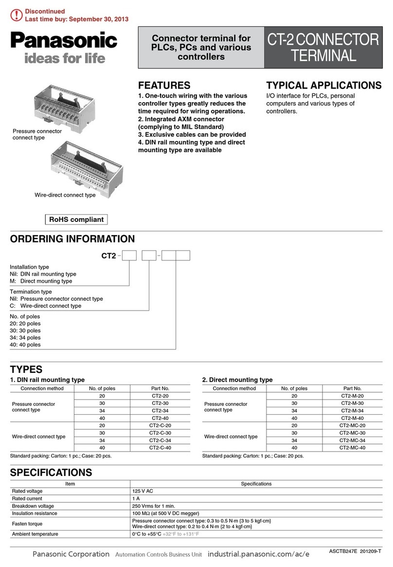
Panasonic CT-2 Series User manual

Panasonic

Panasonic CT-2 Series User manual

Panasonic HMX700 Series User manual

Panasonic

Panasonic HMX700 Series User manual

Panasonic JS-960WS Series User manual

Panasonic

Panasonic JS-960WS Series User manual

Panasonic TY-FB8HM User manual

Panasonic

Panasonic TY-FB8HM User manual

Panasonic TY-FB9HD User manual

Panasonic

Panasonic TY-FB9HD User manual

Panasonic JS-950 Series User manual

Panasonic

Panasonic JS-950 Series User manual

Panasonic JS-925 series User manual

Panasonic

Panasonic JS-925 series User manual

Panasonic HMWIN User manual

Panasonic

Panasonic HMWIN User manual

Panasonic TY-FB9RT User manual

Panasonic

Panasonic TY-FB9RT User manual

Panasonic JS-950 Series User manual

Panasonic

Panasonic JS-950 Series User manual

Panasonic KX-DTU100 User manual

Panasonic

Panasonic KX-DTU100 User manual

Panasonic HMWIN User manual

Panasonic

Panasonic HMWIN User manual

Panasonic JS-960WP0R50 User manual

Panasonic

Panasonic JS-960WP0R50 User manual

Panasonic TZ-PCD2000 User manual

Panasonic

Panasonic TZ-PCD2000 User manual

Panasonic GTWIN User manual

Panasonic

Panasonic GTWIN User manual

Panasonic HM 700 Series User manual

Panasonic

Panasonic HM 700 Series User manual

Panasonic JS-970 Series User manual

Panasonic

Panasonic JS-970 Series User manual

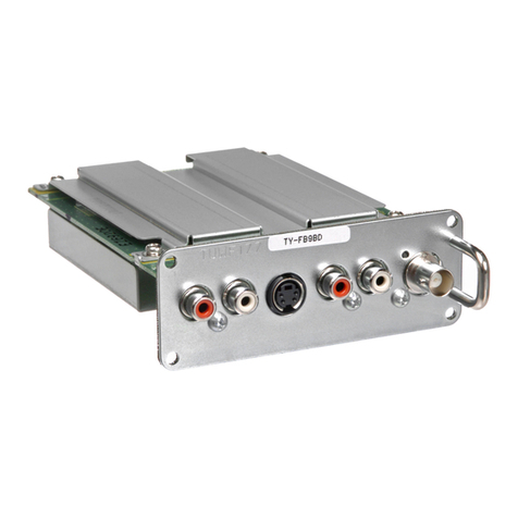
Panasonic TY-FB9BD User manual

Panasonic

Panasonic TY-FB9BD User manual

Panasonic S-LINK SL-TPR4 User manual

Panasonic

Panasonic S-LINK SL-TPR4 User manual

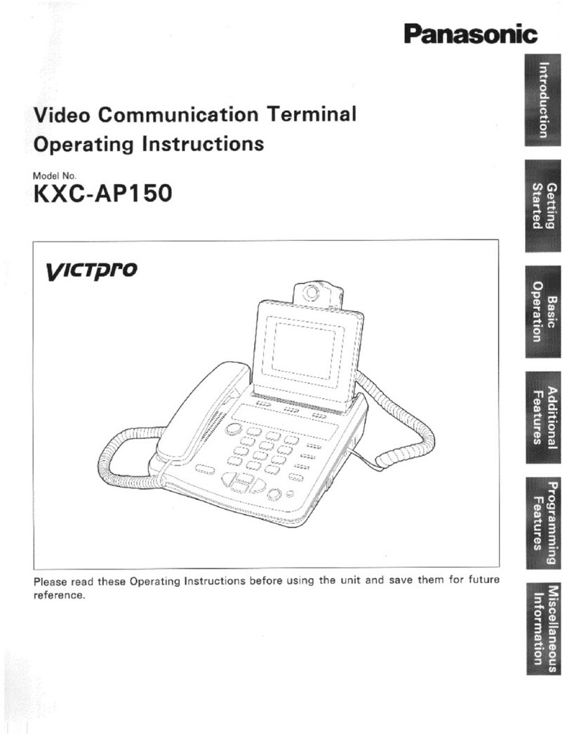
Panasonic KXCAP150 - VIDEO PHONE W/LCD User manual

Panasonic

Panasonic KXCAP150 - VIDEO PHONE W/LCD User manual

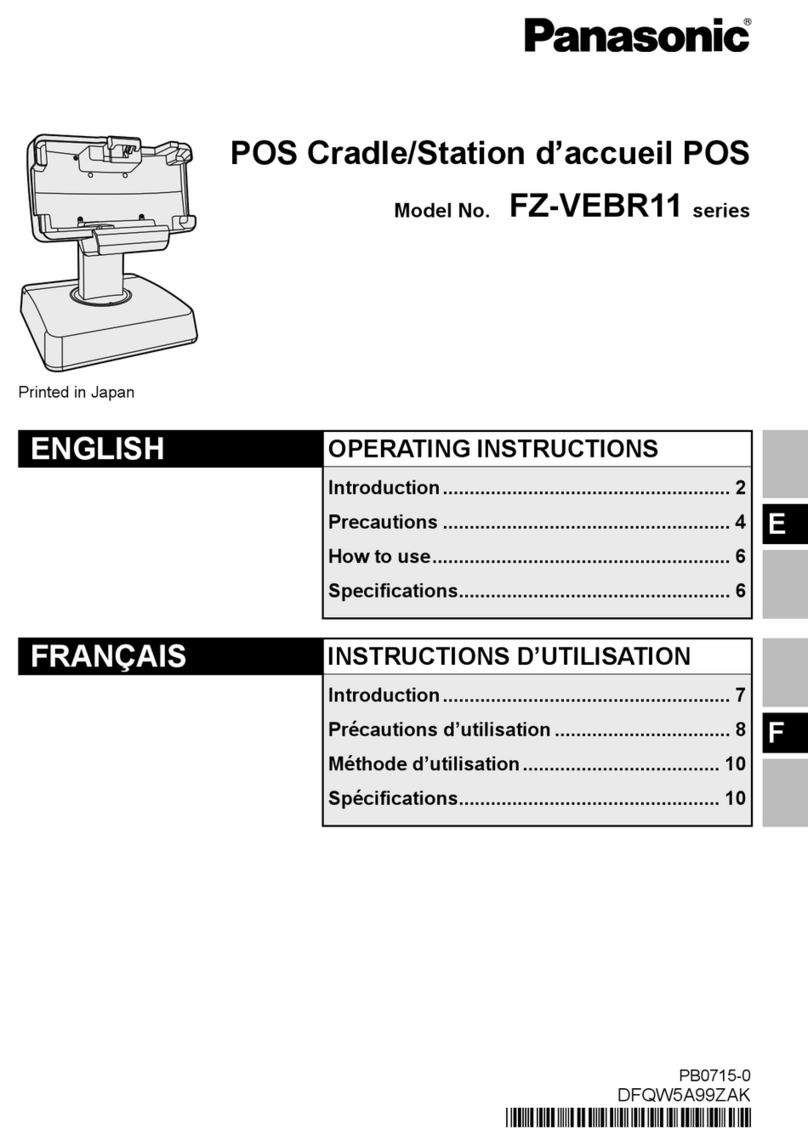
Panasonic FZ-VEBR11 Series User manual

Panasonic

Panasonic FZ-VEBR11 Series User manual

Popular Touch Terminal manuals by other brands

Redline AN-50 user manual

Redline

Redline AN-50 user manual

red lion G306M manual

red lion

red lion G306M manual

protech prox KF-P231 Quick reference guide

protech

protech prox KF-P231 Quick reference guide

Black Box Terminal Eliminator Plus manual

Black Box

Black Box Terminal Eliminator Plus manual

Point Mobile PM80 quick start guide

Point Mobile

Point Mobile PM80 quick start guide

Lenze L-force X400 operating instructions

Lenze

Lenze L-force X400 operating instructions

Samson TROVIS 6616-1 Mounting and operating instructions

Samson

Samson TROVIS 6616-1 Mounting and operating instructions

Satlink FB250 user guide

Satlink

Satlink FB250 user guide

Epson B113111 - DM D500 - Vacuum Fluorescent Display... installation guide

Epson

Epson B113111 - DM D500 - Vacuum Fluorescent Display... installation guide

Siemens TA5P600 operating instructions

Siemens

Siemens TA5P600 operating instructions

Nab QT850 Quick reference guide

Nab

Nab QT850 Quick reference guide

SkyWave IDP 700 Series Hardware guide

SkyWave

SkyWave IDP 700 Series Hardware guide

Qume QVT 101 Maintenance Guide

Qume

Qume QVT 101 Maintenance Guide

KYOWA NTB-500A instruction manual

KYOWA

KYOWA NTB-500A instruction manual

Mitsubishi Electric E1061 installation manual

Mitsubishi Electric

Mitsubishi Electric E1061 installation manual

EchoStar Hughes 45 Series install guide

EchoStar

EchoStar Hughes 45 Series install guide

POSIFLEX RT-6015 user manual

POSIFLEX

POSIFLEX RT-6015 user manual

Ingenico group Desk Series user guide

Ingenico group

Ingenico group Desk Series user guide

manuals.online logo
manuals.online logoBrands
  • About & Mission
  • Contact us
  • Privacy Policy
  • Terms and Conditions

Copyright 2025 Manuals.Online. All Rights Reserved.