manuals.online logo
Brands
  1. Home
  2. •
  3. Brands
  4. •
  5. Ingenico group
  6. •
  7. Touch Terminal
  8. •
  9. Ingenico group Desk Series User manual

Ingenico group Desk Series User manual

Desk Series -
Users Guide
Copyright© 2018-2022
Ingenico All rights
reserved
2
Desk Series
User Guide
www.ingenico.us
Ingenico USA
3025 Winward Plaza
Suite 600
Alpharetta, Georgia 30005 - USA
Desk Series -
Users Guide
Copyright© 2018-2022
Ingenico All rights
reserved
6
User guide
Wall mounted powersupply
unit
Cable connection for the
telephone or Ethernet
network
Terminal Desktop power supply unit required if
terminal is fitted with the following
options:
Radio model (all)
Contactless model
CAUTION
The power supply unit provided with your equipment is specially
designed for it. Do not use any other power supply.
1_Unpacking
According to the model, the following items are included in the packaging box
(including optional accessories):
•
The terminal equipped with its paper roll
•
The power supply with its cable connection (according to the national needs).
•
The cable connection for the telephone or Ethernet network This installation guide
Desk Series -
Users Guide
Copyright© 2018-2022
Ingenico All rights
reserved
13
Ambient temperature
from 0°C to +40°C / 32°F to 104°F
Max relative humidity
85% at +40°C / 104°F
Max altitude
2000 m /
Storage conditions
Storage temperature
-20°C to 55°C / -4°F to 131°F
Max relative humidity
85% at +55°C / 131°F
2_Installation
2_1
Positioning the terminal
Install the terminal on a flat surface, with an easy access to an electrical outlet and
telephone line. Place the terminal away from any heat source and protected from dust,
vibrations
and
electromagnetic
radiations
(away
from
video
terminals,
PC,
anti-
shoplifting barriers, ...).
The
terminal is exclusively made for indoor
use.
Operating conditions
Desk Series -
Users Guide
Copyright© 2018-2022
Ingenico All rights
reserved
14
Telephone
(Optional)*
Power Supply
µSD (Optional)*
SIM 1 & 2
(Optional)*
Serial Link
RS232
Ethernet Link
(Optional)*
10/100 BaseT
USB Host
USB Host/
Slave
2nd Serial Link
RS232
(Optional)*
SAM 1 & 2
SAM 3 (Optional)*
*according to the model
Phone: TNV-3.
Power Supply: Limited Power Source.
Other connections: Safety Extra-low Voltage. According to
IEC60950-1 and EN60950-1
3_1
Connections
All connections are on the rear of the terminal protected by a down-side trapdoor.
Desk Series -
Users Guide
Copyright© 2018-2022
Ingenico All rights
reserved
15
Unclip the trapdoor by pushing on the clip with your finger as shown on the figure
here below.
Then lift the trapdoor rearward to remove it, as shown by arrows on the figure
Closing down-side trapdoor
To close the trapdoor, start by landing
trapdoor on to bottom casing as shown on
the figure , manage 5/6mm distance
for clipinsertion then push and clip
it.
Connecting cables
WARNING
Connecting is to be made when the terminal is powered off.
4_1
Installing the Terminal
-
Cable fixing
Opening down-side trapdoor
Desk Series -
Users Guide
Copyright© 2018-2022
Ingenico All rights
reserved
15
Perform the following operations :
•Open down-side trapdoor
•Plug telephone line with user country specific converter to the telephone
network. Connect the other end to the terminal telephone connection.
•If necessary, connect the telephone (not required for terminal to operate).
•Optionally plug other cables into the appropriate ports (Ethernet, RS232, USB…)
•Plug PSU power lead into the power socket .
•Close down-side trapdoor
•Plug the power supply into the mains.
For instance, possible configuration for France
(*): TNV-3 circuit: Telecommunication Network Voltage, as per safety standard EN 60950-1.
Desk Series Users Guide
Copyright© 2018-2022
Ingenico All rights
reserved
16
WARNING
Connecting is to be made when the terminal is powered off.
Perform operations as described in “connecting cables” chapter and connect cables as
follow:
•Cables to plug:
Power lead Telephone line Ethernet cable
Serial link RS232 cable
Install through-holes in the lead-through guides (as indicated on the
figure).
If you need extra cables then cut undesired over-
molded section at
4_2_1
Kit Magic Box installation (optional)
Desk Series Users Guide
Copyright© 2018-2022
Ingenico All rights
reserved
17
ADVICE
It is strongly recommended to secure the “Magic cable” to terminal’s work
area in order to reduce stress on terminal and connection.
Using the supplied cable tie to attach to a table leg (or similar) Using
the supplied cable tie and self-adhesive support
Using a counter-sunk screw (not supplied) to an appropriate surface
The “Magic Cable” should be readily accessible for terminal maintenance and
helpdesk diagnosis purposes.
NOTE:
The connection Magic Box can also be attached using a VELCRO™ or other
system.
Desk Series Users Guide
Copyright© 2018-2022
Ingenico All rights
reserved
23
5_Installing a paper roll
Your terminal is supplied with one paper roll. When the paper roll is nearing the end, a
red line will appear on the paper; this indicates that the paper roll must be replaced.
CAUTION
Use only paper approved by the manufacturer (diameter 40 mm). Use of
unsuitable paper is likely to damage the printer of your terminal (see paper
characteristicsat “Maintenance”chapter).
•Open the paper compartment by lifting the catch located at the rear of the terminal
and drag the cover to the rear.
CAUTION
Do not force the cover against the cables.
Desk Series Users Guide
Copyright© 2018-2022
Ingenico All rights
reserved
24
•Insert the paper roll in the compartment following the directions shown on the figure
below.
•Pull the paper up to the top of the terminal and hold it in this position.
•Maintain the paper and close the lid.
•Press the top of the lid in the center as shown by arrow, until it clips into position.
ADVICE
If you are inserting a new paper roll remove the first complete turn (this
first turn of sensitive surface could be damaged during shipment).
Desk Series Users Guide
Copyright© 2018-2022
Ingenico All rights
reserved
25
6_Daily use
6_1 Keypad functions
NAVIGATION keys
Ingenico key
CANCEL key (red)
CLEAR key (yellow) / Feed paper (long press)
VALIDATION key (green)
Dot key
Desk Series Users Guide
Copyright© 2018-2022
Ingenico All rights
reserved
26
6_2 Adjusting the contrast (B&W display only)
No contrast management for the Color display
If you wish to increase or to decrease the contrast of the characters displayed on
screen, press simultaneously on the (dot key) and key to decrease the
contrast, or the (dot key) and key to increase it. Keep pressing the keys as
long as necessary.
6_3 Card insertion
6_3_1 Swiping a card
•Insert the card manually in the driver, magstripe
facing the main body of the terminal.
Swipe the card with constant speed, not too slowly not too fast, to
maximize the reading efficiency and avoid annoying repetitions.
6_3_2 Inserting a chip
card
•Chip Cards should be inserted into your terminal
as illustrated with the chip facing up and into the
card reader.
Desk Series Users Guide
Copyright© 2018-2022
Ingenico All rights
reserved
27
6_3_3 Reading Contactless (Optional)
•Bring the card firmly up to the active zone above (at
about 1cm) the contactless logo located on paper
trapdoor button.
•Keep the card close to the contactless logo during
the transaction
•Your contactless terminal provides four contactless
status lights located on display/ lens.
Contactless
Active zone
•When a contactless transaction is started the first (left
hand) status light will be lit steadily; this indicates that
the contactless is in use, but a card is not being read.
•When a contactless card is presented to the
contactless active zone (*) during a transaction the
second, third and fourth status lights will be lit in turn.
The card read is successful when all four status lights
are lit and a confirmation tone can be heard.
Contactless
Status lights
(*): Contactless Symbol is a trademark owned by and used with the permission of EMVCo,
LLC.
CAUTION
Do not stick any conductive label on to contactless active zone located on
paper trapdoor button. It can decrease seriously contactless efficiency.
6_3_4 Headphone output (Optional)
•The headphone output jack is located under the card reader outlet. This option is not
designed to play music, but to facilitate the use by blind people.

Other Ingenico group Touch Terminal manuals
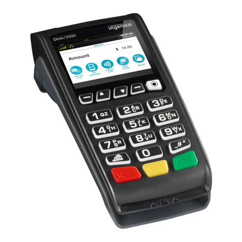
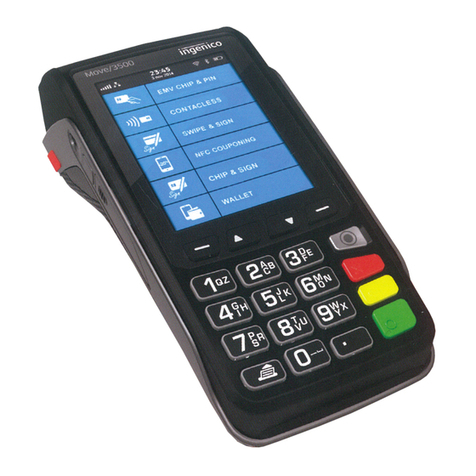
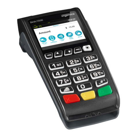
Ingenico group Desk 3500 User manual

Ingenico group

Ingenico group Desk 3500 User manual

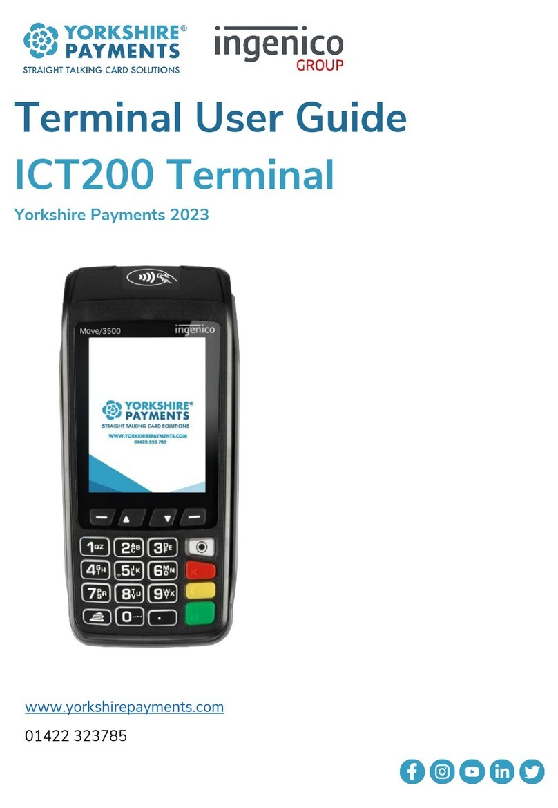
Ingenico group Yorkshire Payments ICT200 User manual

Ingenico group

Ingenico group Yorkshire Payments ICT200 User manual

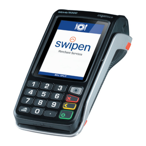
Ingenico group swipen Move 5000 User manual

Ingenico group

Ingenico group swipen Move 5000 User manual

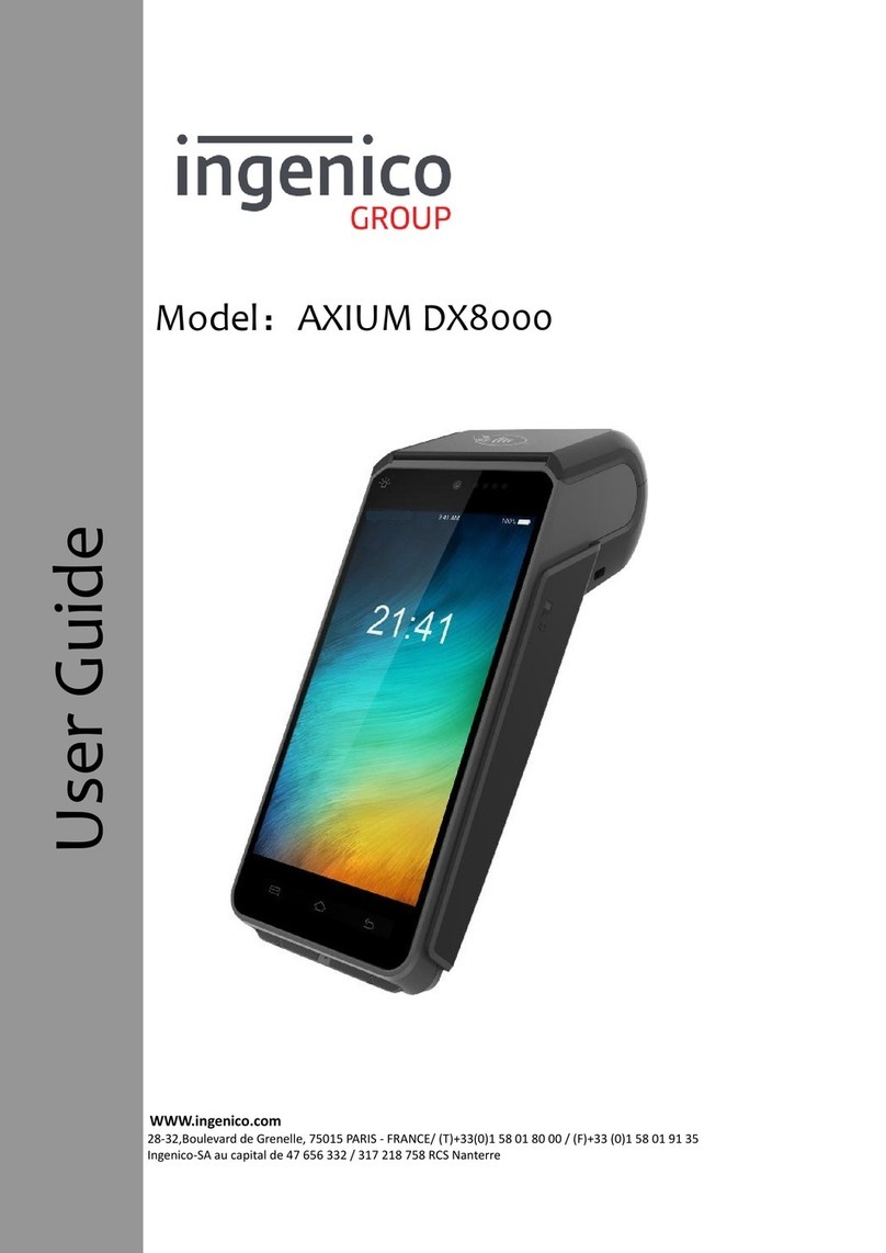
Ingenico group AXIUM DX8000 User manual

Ingenico group

Ingenico group AXIUM DX8000 User manual

Ingenico group Link/2500 User manual

Ingenico group

Ingenico group Link/2500 User manual

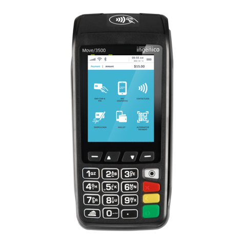
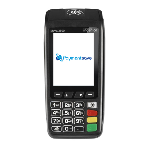
Ingenico group Move/3500 User manual

Ingenico group

Ingenico group Move/3500 User manual
Ingenico group swipen Desk 5000 User manual

Ingenico group

Ingenico group swipen Desk 5000 User manual

Ingenico group AXIUM DX8000-BASE-W2 User manual

Ingenico group

Ingenico group AXIUM DX8000-BASE-W2 User manual

Ingenico group EX8000 User manual

Ingenico group

Ingenico group EX8000 User manual

Ingenico group Desk 3500 User manual

Ingenico group

Ingenico group Desk 3500 User manual

Ingenico group iSMP v4 Wi-Fi User manual

Ingenico group

Ingenico group iSMP v4 Wi-Fi User manual

Ingenico group Move 3500 WiFi User manual

Ingenico group

Ingenico group Move 3500 WiFi User manual

Ingenico group AXIUM DX4000 User manual

Ingenico group

Ingenico group AXIUM DX4000 User manual

Ingenico group iPP300 Series User manual
Ingenico group

Ingenico group iPP300 Series User manual

Ingenico group Move 3500 MIX User manual

Ingenico group

Ingenico group Move 3500 MIX User manual

Ingenico group Move 3500 3G User manual
Ingenico group

Ingenico group Move 3500 3G User manual

Ingenico group Move 3500 BLUETOOTH User manual
Ingenico group

Ingenico group Move 3500 BLUETOOTH User manual

Popular Touch Terminal manuals by other brands

Zte AR910 user manual

Zte

Zte AR910 user manual

EZCheck OMNI 3730 instruction manual

EZCheck

EZCheck OMNI 3730 instruction manual

Advantech POC-195 user manual

Advantech

Advantech POC-195 user manual

SEWOO NBP-60 user manual

SEWOO

SEWOO NBP-60 user manual

Ingenico AXIUM DOCK user guide

Ingenico

Ingenico AXIUM DOCK user guide

POSBank AnyShop Eco user manual

POSBank

POSBank AnyShop Eco user manual

Huawei ETS2052 user guide

Huawei

Huawei ETS2052 user guide

ZKTeco TF1700 quick start guide

ZKTeco

ZKTeco TF1700 quick start guide

Mitsubishi F940WGOT-TWD installation manual

Mitsubishi

Mitsubishi F940WGOT-TWD installation manual

XIEGU GSOC Operation manual

XIEGU

XIEGU GSOC Operation manual

POSIFLEX KV-2000 Series user manual

POSIFLEX

POSIFLEX KV-2000 Series user manual

Spectra Technologies APOLLO TA10V installation guide

Spectra Technologies

Spectra Technologies APOLLO TA10V installation guide

Huawei ETS2059 user guide

Huawei

Huawei ETS2059 user guide

Pax Technology SP20 instruction manual

Pax Technology

Pax Technology SP20 instruction manual

Omron NS7 Series Setup manual

Omron

Omron NS7 Series Setup manual

Emerson FB1100 Replacement guide

Emerson

Emerson FB1100 Replacement guide

Cinterion MC55i Hardware interface description

Cinterion

Cinterion MC55i Hardware interface description

Beckhoff KS2535, KL2545 manual

Beckhoff

Beckhoff KS2535, KL2545 manual

manuals.online logo
manuals.online logoBrands
  • About & Mission
  • Contact us
  • Privacy Policy
  • Terms and Conditions

Copyright 2025 Manuals.Online. All Rights Reserved.