Panthera AB, Gunnebogatan 26, SE-163 53 Spånga, Sweden, +46-8-761 50 40, www.panthera.se
ASSEMBLY INSTRUCTIONS
art.nr. 8822140
Rev.2021-01
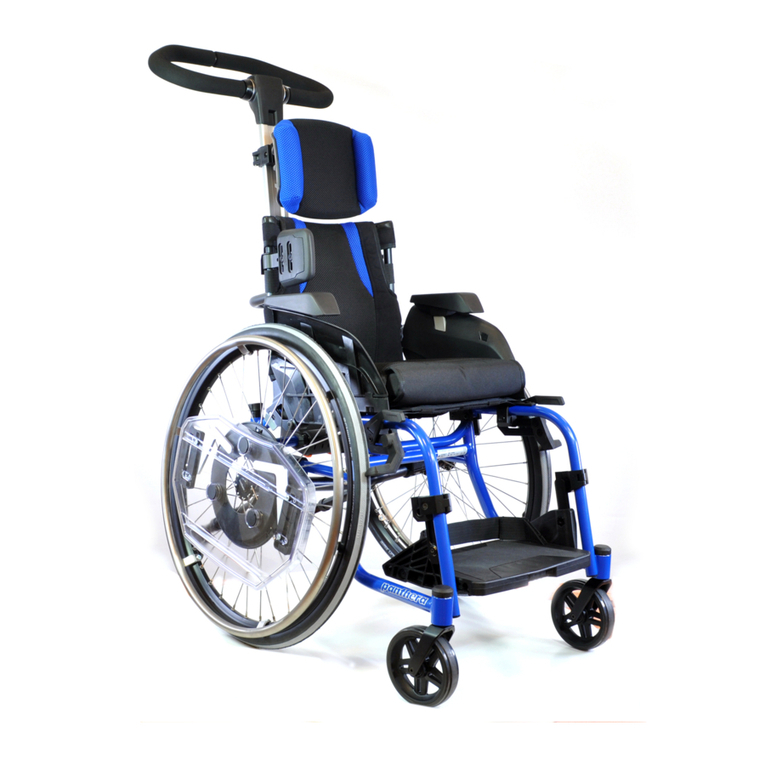
FOOT PLATE BAMBINO 3
Assembly instructions for:
Foot plate Bambino 3
art.nr. 42341WW
Tool aquired:
Allen key 4 mm
Allen key 5 mm
• The foot plate can be raised and lowered .
• The foot plate can be assembled in two dierent positions. A ”low
position” (default) and a ”high position”.
• The angle of the foot plate can be adjusted.
• Can be adjusted in two depth positions, front and rear.
• The foot plate can be folded backwards
•The foot plate can be locked in lowered position.
1) Height adjustment
On both sides, loosen (slightly) the screw (1)
with a 5 mm Allen key. Adjust the footplate
to the desired height, then tighten the
screws.
2) Height adjustment -LOW position
Default is the footplate mounted in ”low posi-
tion”. If necessary, you can turn the brackets
and mount the foot plate in an extra high posi-
tion (See pictures 3 and 4)
3) Height adjustment -HIGH position
The foot plate mounted in ”high position”
with brackets turned around.
4) Switch between high and low position
1. Loosen the screw for angle adjustment
(no. 1 in Fig. 5) with a 5 mm Allen key.
2. Loosen and remove screw and washer (1)
with a 4 mm Allen key and nut completely
on both sides.
3. Remove the footplate.
4. Insert nut on the inside of the footrest,
turn the bar (2) 180 degrees, push the nut
through the bar (2), fasten the screw from
the outside.
Repeat on the other side.
5. Tighten screws (1) from the outside.
6. Tighten the angle adjustment screws (1 in
Fig. 5) to 15 Nm.
5) Angle adjustment
Loosen the screws (1) with a 5 mm Allen key
and adjust the footplate to the desired angle.
Tighten the screws to 15Nm
6) Depth adjustment
Can be adjusted in two depth positions
front (A) and rear (B)
1. Fold up the footplate (gure 7)
2. On both sides, loosen and remove the
screws (1) with 4 mm Allen key.
2. Push out the nut sleeve from the outside
on both sides and remove the footplate.
Press the nut sleeve on one side and insert
the foot plate in the desired position A or B,
repeating on the other side.
4. Reattach the screws (1) and tighten.
5. Slide the catches (1 in Fig. 7) to the op-
posite side, lower the footplate.
1 2 3
4 5 6


