9
FIGURE 9
0123456
1/2 1/2 1/2 1/2 1/2 1/2
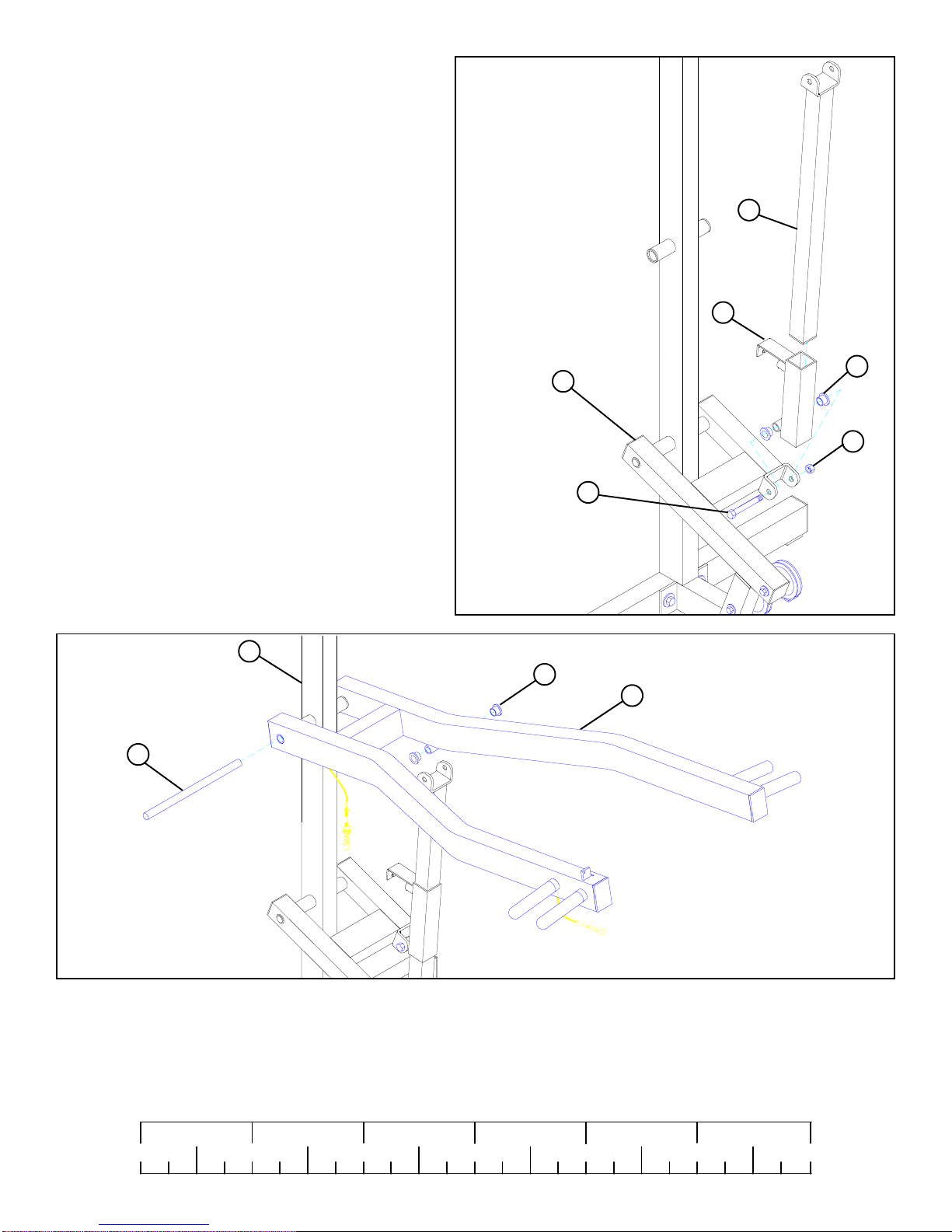
FIGURE 10
DETAIL 9
DETAIL 9
1/4” NUTS
PUSH/PULL
CABLE
SPRING PIN
ASSEMBLY
13
DO NOT OVERTIGHTEN!
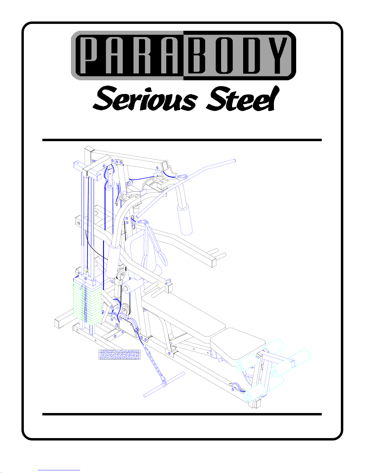
Assemble the PUSH/PULL CABLE from the PRESS ARM (8) to the SPRING PIN HOUSING and to the L-BRACKET on the
RECEIVING TUBE (13) as shown on FIGURE 9 and DETAIL 9 using the following steps:
STEP 9
·Thread the first 1/4-28 IN. NUT to the bottom of the threaded end of the CABLE. Allow the other 1/4-28 IN. NUT to hang loose
on the exposed CABLE until the SPRING PIN ASSEMBLY is attached.
·Securely assemble the SPRING PIN ASSEMBLY to the
SPRING PIN BARREL. (!!! IMPORTANT !!! TIGHTEN
THE NUT OF THE SPRING PIN ASSEMBLY SE-
CURELY)
·Swing the PRESS ARM (8) up until the SPRING PIN of the
PUSH/PULL CABLE engages in one of the adjustment
holes.
· Thread the second 1/4-28 IN. NUT onto the threaded end of
the CABLE, and cinch the two 1/4-28 IN. NUTS around the
flat.
·Use the extra thread on the end of the CABLE to adjust out
slack. ( !!! DO NOT ADJUST OUT TO FAR !!! AL-
WAYSALLOW SPRINGPIN ASSEMBLYTO FULLY
ENGAGE)
STEP 10
• Securely tighten two 5/32” SET SCREWS (65) and insert
two 3 X 2” END CAPS (75) into the open ends of PRESS
ARM (8) as shown in FIGURE 10.
• Securely tighten two 5/32" SET SCREWS (65) and insert
two 2” SQ. END CAPS (76) into the open ends of PRESS
ARM LEVER (9) as shown in FIGURE 10.
• Securely tighten one 3/8 X 1” BOLT (35), one 3/8” WASHER
(51), and one 3/8” LOCKNUT (48) to the bottom of AD-
JUSTMENT SLIDE (6) as shown in FIGURE 10.
• Insert one 1-3/4” SQ. END CAP (77) into the end of AD-
JUSTMENT SLIDE (6) as shown in FIGURE 10.
48
76
51
65
75
65
6
77
9
8
3/8 X 1” 35
8
13